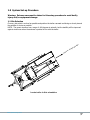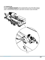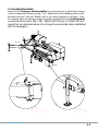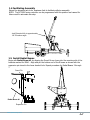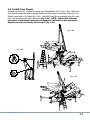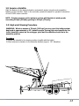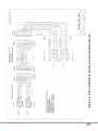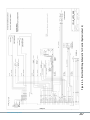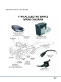
1
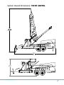
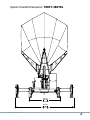
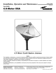
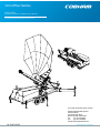
3.8m Offset Mobile
TXINT-380TRL
Assembly, Operation, and Maintenance Manual
The most important thing we build is trust
For further information please contact:
Cobham SATCOM land Systems
Patriot Products
704 North Clark Street
Albion, Michigan 49224 USA
Tel:
(01) 517 629 5990
Fax:
(01) 517 629 6690
[email protected]
2M-TXINT-380TRL
www.cobham.com/patriot
Table of Contents
Warranty/Disclaimer ..............................................................................3
Warnings and Cautions ..........................................................................4
Introduction and Equipment Overview ...................................................6
System Overall Dimensions ....................................................................7
1.0 System Set-up Procedure .................................................................9
1.1 Site Selection . . . . . . . . . . . . . 8
1.2 Install Feed . . . . . . . . . . . . . . 9
1.3 Leveling the Trailer . . . . . . . . . . 10
1.4 Facilitating Assembly . . . . . . . . 11
1.5 Install Radial Beams . . . . . . . . . 11
1.6 Install Inner Panels . . . . . . . . . 12
1.7 Install Outer Panels . . . . . . . . . 13
1.8 Acquire a Satellite . . . . . . . . . . 14
2.0 High Wind Stowing Procedure .........................................................15
3.0 Disassembly of the Reflector ...........................................................16
4.0 Feed Stowing Procedure .................................................................16
5.0 Towing ..........................................................................................16
6.0 Periodic Preventive Maintenance .....................................................17
6.1 General
6.2 General Cleaning
6.3 Inspection and Preventive Maintenance
7.0 Hardware Tensioning Procedure ......................................................19
8.0 Preservation of Component Parts ....................................................19
8.1 Aluminum Parts
8.2 Painted and Galvanized Steel surfaces
8.3 Plastic Parts
9.0 Lubrication ....................................................................................20
9.1 General Lubrication comments
9.2
9.3
9.4
9.5
Elevation Jack
Motor Gearbox/Housing Fill and Drain instructions
Drive Chain Lubrication Requirements
Lubrication Schedule
10.0 Specifications ......................................................................................Back Cover
www.cobham.com/patriot
2
LIMITED TWELVE (12) MONTH WARRANTY
This COBHAM SATCOM Patriot product is warranted to be free from defects in material and
workmanship under normal use and service. Patriot antenna products shall repair or replace defective
equipment, at no charge, or at its option, refund the purchase price, if the equipment is returned to Patriot
products not more than twelve (12) months after shipment. Removal or reinstallation of equipment and its
transportation shall not be at cost of COBHAM SATCOM Patriot product except Patriot product shall return
repaired or replaced equipment freight prepaid.
This Warranty shall not apply to equipment which has been repaired or altered in any way so as to affect
its stability or durability, or which has been subject to misuse, negligence or accident. This Warranty does
not cover equipment which has been impaired by severe weather conditions such as excessive wind, ice,
storms, lightning, or other natural occurrences over which COBHAM SATCOM Patriot products has no
control, and this Warranty shall not apply to equipment which has been operated or installed other than in
accordance with the instructions furnished by COBHAM SATCOM Patriot products.
Claimants under this Warranty shall present their claims along with the defective equipment to COBHAM
SATCOM Patriot products immediately upon failure. Noncompliance with any part of this claim procedure
may invalidate this warranty in whole or in part.
THIS WARRANTY IS EXPRESSLY IN LIEU OF ALL OTHER AGREEMENTS AND WARRANTIES, ANY IMPLIED
WARRANTY OF MERCHANTABILITY OR FITNESS FOR A PARTICULAR PURPOSE IS LIMITED IN DURATION
TO THE DURATION OF THIS WARRANTY. PATRIOT ANTENNA DOES NOT AUTHORIZE ANY PERSON TO ASSUME FOR IT THE OBLIGATIONS CONTAINED IN THIS WARRANTY AND
PATRIOT ANTENNA NEITHER ASSUMES NOR AUTHORIZES ANY REPRESENTATIVE OR OTHER
PERSON TO ASSUME FOR IT ANY OTHER LIABILITY IN CONNECTION WITH THE EQUIPMENT
DELIVERED OR PROVIDED.
IN NO EVENT SHALL COBHAM SATCOM PATRIOT ANTENNA PRODUCTS BE LIABLE FOR ANY LOSS OF
PROFITS, LOSS OF USE, INTERRUPTION OF BUSINESS, OR INDIRECT, SPECIAL OR
CONSEQUENTIAL DAMAGES OF ANY KIND.
In no event shall COBHAM SATCOM Patriot products be liable for damages in an amount greater than the
purchase price of the equipment.
Some states do not allow limitations on how long an implied warranty lasts, or allow the exclusion or
limitation of incidental or consequential damages, so the above limitations or exclusions may not apply to
you.
COBHAM SATCOM Patriot products has the right to void the warranty when the antenna is installed by
someone other then a certified installer.
Product Serial Number- _________________
Date Purchased- _________________
Cobham SATCOM Land Systems
Patriot Products
704 North Clark Street
Albion, MI 49224 USA
Tel: (517)629-5990
Fax: (517)629-6690
[email protected]
www.cobham.com/patriot
3
IMPORTANT!!!
INSTALLATION OF THIS PRODUCT SHOULD BE PERFORMED ONLY BY A PROFESSIONAL INSTALLER AND IS NOT RECOMMENDED FOR CONSUMER D.I.Y.
(DO-IT-YOURSELF) INSTALLATIONS.
WATCH FOR WIRES!
Installation of this product near power lines is dangerous. For your
own safety, follow these important safety rules.
1. Perform as many functions as possible on the ground.
2. Watch out for overhead power lines. Check the distance to the power lines before starting
installation.
We recommend you stay a minimum of 6 meters (20 feet) from all power lines.
3. Do not use metal ladders.
4. Do not install antenna or mast assembly on a windy day.
5. If you start to drop antenna or mast assembly, get away from it and let if fall.
6. If any part of the antenna or mast assembly comes in contact with a power line, call your
local power company. DO NOT TRY TO REMOVE IT YOURSELF! They will remove it safely.
7. Make sure that the mast assembly is properly grounded.
WARNING
Assembling dish antennas on windy days can be dangerous. Because of the antenna surface,
even slight winds create strong forces. For example, a 1.0m antenna facing a wind of 32 km/h
(20 mph) can undergo forces of 269 N (60 lbs.). Be prepared to safely handle these forces at
unexpected moments. Do not attempt to assemble, move or mount dish on windy days or
serious, even fatal accidents may occur. COBHAM SATCOM Patriot antenna product is not
responsible or liable for damage or injury resulting from antenna installations.
www.cobham.com/patriot
4
Introduction
Thank you for purching your Cobham SATCOM Patriot Products antenna. We trust that you will find
this to be a well designed product that will proved many years of reliable service. Please read this
manual thoroughly before beginning assembly. For best results in the assembly process, perform
each step in the same sequence as listed in this manual. Record the serial munber of the unit on to
page two for future refferance and read the warrenty information. The serial number plate can be
found on the pedestal mount.
IMPORTANT!
Set-up and use of this equipment should be performed only by professional technicians and is not
recommended for consumer use.
WATCH FOR WIRES!
Set-up and use of this product near power lines is dangerous. For your own safety, follow these
important safety rules.
GENERAL WIND WARNING!
Assembling dish antennas on windy days can be dangerous. Because of the antenna surface, even slight
winds create strong forces. For example, a 1.0m antenna facing a wind of 20 mph [32 kph] can undergo
forces of 60 lbs. [269 N]. Be prepared to safely handle these forces at unexpected moments. Do not
attempt to assemble, move or mount dish on windy days or serious, even fatal accidents may occur.
Cobham SATCOM Patriot Products is not responsible or liable for damage or injury resulting from antenna
installations or deployments.
SYSTEM-SPECIFIC WIND WARNING!
The pointing accuracy of this antenna system will diminish at wind speeds exceeding 30 mph [48 kph]
(45 mph [72 kph] gusts) while winds in excess of 70 mph [112 kph] can turn over this trailer system
deployed at approximately a 25° elevation angle. Therefore, do not operate this system at wind speeds
exceeding 65 mph [104 kph]. If winds in excess of 65 mph [104 kph] are imminent or expected, rapidly
adjust a deployed antenna to the High-wind Stowed position (see section 2.0, pg.14). In that position,
this antenna system will survive 100 mph [161 kph] winds. If there is adequate notice, this trailer system
(unassembled and containerized) will survive 125mph [201 kph] winds.
www.cobham.com/patriot
5
Introduction
This manual has (3) main sections:
Operation
Electrical
Maintenance
The Operation section contains detailed operating procedures for deployment and normal
operation of the antenna system. The Maintenance section contains preventative maintenance
procedures to keep the system in top operating condition for many years of reliable service.
Equipment Overview
The Patriot 3.8m Offset Mobile Antenna System is comprised of a custom trailer designed with
outriggers to provide a stable platform for the deployed antenna assembly, and the necessary
storage compartments for the unassembled antenna and integration components during
transport.
The Antenna system is comprised of a motorized mount assembly that transports in a stowed
position and quickly assembles by adding (7) Radial Beams and (12) Panel sections to a
central Hub. The reflector surface is very rigid and accurately held in shape by means of
latches and precision alignment pins. Only (2) six-foot folding ladders are required for set-up.
The mechanical positioning is capable of ±90° in azimuth and 0 to 110° in elevation at a slew
rate of 1° per second.
An RCI3000 series controller is integrated with the system providing the following capabilities:
Stow
Auto Satellite acquisition
www.cobham.com/patriot
6
System Overall Dimensions: TXINT-380TRL
275 5/8"
7002
MAX HEIGHT
268 1/4"
6814
99
2504
MAX HEIGHT
STOWED
www.cobham.com/patriot
7
System Overall Dimensions: TXINT-380TRL
103 1/8"
2619
STOWED
195 3/8"
4964
DEPLOYED
www.cobham.com/patriot
8
1.0 System Set-up Procedure
Warning: Extreme care must be taken for this setup procedure to avoid bodily
injury and/or equipment damage.
1.1 Site Selection
Choose a site which is as level as possible and position the trailer rearward end facing as closely toward
the satellite of choice as possible.
NOTE: The mount structure has a range of ±90 degrees in azimuth, but the stability will be improved
against wind forces when the antenna is pointed in-line with the trailer.
ion
ct
ire
D
o
t
ge
r
f ta
llite
te
Sa
Locate trailer in this orientation
www.cobham.com/patriot
9
1.2 Install Feed
Remove the Feed Pallet Assembly from its nested position in the Feed & Utility Container.
Install the Feed Pallet Assembly with the desired Feed System and connect all applicable
cables. Locate Feed Pallet using pins on plate bottom and secure in place with latches.
DETAIL A
SCALE 1 : 8
A
A
www.cobham.com/patriot
DETAIL A
SCALE 1 : 8
10
1.3 Leveling the trailer
Deploy the four Outrigger Jack Assemblies by removing the pin to allow them to swing
out into position then re-insert pin (fig. 1.3a). Adjust each of the stabilizing jacks to level
the trailer using the “bulls-eye” Bubble Level on the mount pedestal as a reference. Once
the outrigger jacks are deployed, swing into position and extend the two Auxilliary Jacks
mounted behind the fenders (fig. 1.3b). Adjust until they are in contact with the
ground but not extended where they change the pre-leveled setup established
with the Outriggers.
fig. 1.3a
DETAIL fig. 1.3a
SCALE 1 : 8
DETAIL fig. 1.3a
SCALE 1 : 8
fig. 1.3b
fig. 1.3b
DETAIL fig. 1.3b
SCALE 1 : 8
fig.
1.3a fig. 1.3a
DETAIL
SCALE 1 : 8
www.cobham.com/patriot
DETAIL
fig. 1.3b
fig.
1.3b
SCALE 1 : 8
11
1.4 Facilitating Assembly
Extend the elevation jack to its’ maximum limit to facilitate reflector assembly.
NOTE: The RCI3000 series controller can be programmed with this position and named for
future recall to automate this step.
Jack Extended fully to approximately
110° Elevation angle
1.5 Install Radial Beams
Begin with Radial Beam #1 by aligning the Dowel Pin as shown into the receiving slot of the
brackets marked for RB#1. Align and pin the bottom end of the R-beam as shown with the
expansion pin stored in the lower bracket hole. Repeat procedure for Radial Beams 2 through
7.
Dowel Pin
Radial Beam #1
Expansion Pin
www.cobham.com/patriot
12
1.6 Install Inner Panels
Starting with Panel #1, position the panel over Radial Beams #1 & 2 (fig. 1.6a). Slide front
end of panel toward the hub to engage small end of the panel, interlocking it with the Top
Strap on each side of the panel (fig. 1.6b). Align the Dowel Pin engagement near the Latch
(fig. 1.6a) and secure the Latch as shown (fig. 1.6b). NOTE: Some slight sideways
movement of the Radial beams may be needed to facilitate the pin alignments.
Repeat procedure for Panels #2 through 6 (fig. 1.6c).
fig. 1.6a
fig. 1.6b
fig. 1.6c
www.cobham.com/patriot
13
1.7 Install Outer Panels
Align the Dowel Pin engagements on Outer Panel end faces adjacent to the Inner Panels
(fig. 1.7a). Then align the pins in the back of the panel with the holes in the Radial Beams as
done with the Inner Panels. Latch Panels to the Radial Beams first, then secure the Latches on
the perimeter seams working from the center to the sides (fig. 1.7b).
NOTE: Be sure all latches are securely locked and all radial beams are securely
pinned before moving the reflector from this assembly position.
fig. 1.7a
fig. 1.7a
DETAIL fig. 1.7a
SCALE 1 : 10
DETAIL fig. 1.7a
SCALE 1 : 10
fig. 1.7b
fig. 1.7b
DETAIL fig. 1.7b
SCALE 1 : 2
DETAIL fig. 1.7b
SCALE 1 : 2
www.cobham.com/patriot
14
1.8 Acquire a Satellite
Sight the antenna to the desired elevation and azimuth angles using the auto acquisition
function of the controller. Refer to the controller operations manual for operation instructions
of the RCI3000 series controller.
NOTE: Pointing accuracy of the antenna system will diminish at wind speeds
exceeding 30 mph [48 kph] (gusting to 45 mph [72 kph]).
2.0 High wind Stowing Procedure
WARNING: Winds in excess of 70 mph [112 kph] can turn over this trailer system
deployed at approximately a 25° elevation angle. During High wind conditions the
trailer should be raised on the outrigger jacks and the reflector should be in the
assembly position.
Procedure
1) Rotate the azimuth to the stowing position (parallel with the trailer).
2) Move antenna in elevation to the assembly position (approx. 110° elevation).
www.cobham.com/patriot
15
3.0 Disassembly of the Reflector
These steps are essentially the reverse order of assembly. Begin by calling up the position
used for assembly set-up in the RCI controller. Release the latches beginning with panel
#12; perimeter latches first, then the latches securing the panel to the Radial Beams. Repeat
for outer panels #11 through #7, then also for inner panels #6 through #1. Place panels in
corresponding marked locations in the panel storage container, making sure rigid foam dividers
and protectors are properly in-place. Finally, dis-assemble Radial Beams #7 through #1 by
removing the expansion pins, lifting the Radial Beams out of the hub slots, and placing all
of these components into the Radial Beam storage container in the corresponding nesting
locations.
4.0 Feed Stowing Procedure
With the Reflector Panels and Radial Beams dis-assembled from the hub and stored, initiate
the stow routine on the RCI3000 series controller. Disconnect the Feed Pallet Assembly from
the Feed Support structure undoing the latches and storing the feed system in the Feed &
Utility Container. All cable ends should be secured with proper terminations for weather-tight
protection during transport.
5.0 Towing
Caution: Be sure the front trailer jack is contacting the ground before
raising the outrigger jacks.
5.1 When hooking the trailer to the tow vehicle, position trailer tongue over ball hitch and
carefully lower jack to engage hitch assembly. Ensure that the trailer jack is fully retracted and
tilted into its tow position before towing.
5.2 The safety chains should be crossed under the tongue and connected to the tow vehicle.
The breakaway cable should be connected solidly to the frame or bumper of the tow vehicle
with just enough slack to allow cornering.
5.3 Hook up the electrical pin connector and check that all brake, signal and turning lights are
properly working.
www.cobham.com/patriot
16
6.0 Periodic Preventive Maintenance
6.1 General
This section contains periodic preventive maintenance procedures including cleaning,
lubrication and painting procedures deemed within the capabilities of the average station
technician.
An operation checkout procedure provides an accurate indication of the overall earth station
performance and should be performed at monthly intervals or after extended periods of
storage or long distances of travel (in excess of 500 miles).
Warning: Service personnel must at all times observe all safety regulations. Do not perform
any maintenance task on the equipment without first turning off the main power supply.
Under certain conditions, dangerous potentials may exist when the power is off due to charges
retained by capacitors. Always discharge and ground a circuit after removing power.
6.2 General cleaning
To prevent the excessive accumulation of dust and dirt, thoroughly clean the equipment
whenever visually inspecting the system. No special cleaning procedures are required (unless
noted).
A. Electrical Parts. Use a soft brush, lint-free cloth or clean compressed air (25psi) to remove
dust and loose foreign particles.
B. Mechanical Parts. Clean mechanical parts by first removing dust, dirt and other loose
contaminants with a scraper, stiff brush (bristle, or wire in the case of rust or other corrosion)
or cloth or compressed air (25 psi). Any accumulated deposits that require further cleaning
may be removed with a bristle or wire brush and a cleaning solvent such as trichloroethylene,
or equal. Ensure that surfaces of reflector alignment pins, latches and their adjacent edge and
rib surfaces remain free of dirt build-up and any other foreign matter. Clean and paint aluminum,
galvanized and plastic surfaces in accordance with the procedures outlined below.
6.3 Inspection and Preventive Maintenance
The frequency of inspection is contingent upon the user’s individual standards and the
operational environment in which the earth station is located. However, a visual inspection of
the system should be performed at least monthly. Do not attempt to clean resolver assemblies
or the feed motorization assembly unless they are malfunctioning. Inspect the surface of
the reflector to ensure it is free of dirt and other foreign matter. Any condition noted during
inspection that may preclude continued proper operation of the system should be corrected
(repaired or replaced) immediately or if not deemed operational contingent, then on the next
scheduled maintenance inspection.
A. Trailer
1. Check tire pressure, maintain 85 psi.
2. Check tires for excessive wear.
3. Lubricate the four corner jacks and the trailer jack.
4. Check ball on the towing vehicle for wear or damage.
5. Check the fluid level in the brake system, and maintain per owners maintenance manual.
6. Check brake linings for wear. Replace shoes if necessary.
7. Adjust brakes per owner’s maintenance manual.
8. Check battery back-up system. Ensure reliable charge.
9. Inspect all wiring and lights for wear or damage.
10. Visually inspect for loose or missing hardware. Replace and/or re-torque as required.
www.cobham.com/patriot
17
6.3 Inspection and Preventive Maintenance (cont)
B. Antenna/Positioner.
Inspection of the antenna conforms generally to standard visual inspection procedures
performed on electromechanical equipment. In addition to these standard procedures,
perform the following checks and visual inspections for the specific conditions noted:
1. Inspect all wiring, flexible waveguide, rigid waveguide and cables for discoloration and
burned insulation, moisture entry, corrosion, dirt, breaks, secure connection, physical
damage and other signs of deterioration. Examine connections for dirt, corrosion and
mechanical defects. Check for loose or broken lacing and cut, abraded, frayed, brittle and
cracked insulation.
2. Examine connectors for corrosion, broken inserts and stripped threads. Check connector
shells for distortion and dents, and contact pins for bends, misalignment or other
deformities. Check connector inserts for cracks, and carbon tracking, burns or charring
indicating arc-over.
3. Check all electrical components for dirt, cracks, chips, breaks, discoloration and other signs
of deterioration and damage indicating overload.
4. Inspect the drive chain on the azimuth D-Ring assembly. It should be well greased. Clean
and/or remove any old grease that is contaminated or is hardening.
5. Operate the azimuth and elevation drives as well as the feed rotation in both directions at
least once a month. Ensure that the antenna is under observation during operation
to prevent injury or damage. Check that the limit switches at the extremes of travel are
functioning and that the hardware is tight.
6. Check the motors for signs of water intrusion.
7. Check the Elevation jack boot that it is properly secured and has no damage that may
expose the jackscrew. Minor repairs can be made with RTV.
8. After system operation, remove feed system and visually inspect the feed window for
dirt and the feed and feed window for distortion, foreign object damage and environmental
deterioration due to ice and snow, dust, rain, hail and high winds, etc., which may cause
electrical component and/or structural deformation.
9. Check the cable attachment to the resolvers and the cable insulation for cuts, cracking,
abrasion and other deterioration. Check the resolvers for a secure mechanical attachment.
10. Visually inspect all mechanical parts for freedom of operation with no misalignment,
binding or interference. Check all cabling for sufficient slack to prevent cable strain as well
as adequate restraint to prevent abrasion or chaffing during antenna feed movement.
11. Check security of antenna mounting and interconnecting assembly hardware. Replace
rather than tighten any loose A-325 structural hardware. The hardware distorts at initial
installation and once loosened, will not maintain the required high-strength friction
connection. All other assembly and installation hardware should be tightened to its original
torqued condition. Use a thread-locking compound when installing new hardware.
12. Examine painted aluminum and galvanized surfaces and touch-up where required in
accordance with the procedures outlined in- Preservation of Component Parts.
NOTE: Do not paint exposed surfaces of latches or where precision
dowel interface or expansion pins are located.
www.cobham.com/patriot
18
7.0 Hardware Tensioning Procedure
1. Lubricate bolt threads with stick wax to reduce friction. Do not allow wax under flat
washer.
2. After connections are completed, tighten bolts until surfaces are joined and nuts are snug.
Do not proceed with Steps 3 and 4 below unless the connection is final. If bolts are
loosened after Steps 3 & 4 discard and replace with new hardware. Repeat all steps.
3. Mark nuts and end of bolts with straight line. (see Fig. A)
4. Tighten nuts further with extra long wrench or power wrench until nuts are moved an
additional 1/3 turn (120º ±30º). (see Fig. B)
5. If bolt length exceeds four diameters, further tighten nuts until they are moved a total of
180°. (see fig. C)
Use Felt Marker
A. Before Tensioning
B. After Tensioning
C. After Tensioning >4X
Length/Dia. Bolts
8.0 Preservation of Component Parts
8.1 Aluminum Parts
Remove all loose paint and corrosion by scraping, wire brushing of using steel wool. Edges of
existing paint can be blended with the metal surface by using a fine grit sandpaper. Wipe the
surface to be painted with a soft rag dampened in trichloroethylene, lacquer thinner or equal.
Be certain to remove all loose paint, corrosion, imbedded dirt, grease and oil deposits or the
paint will not adhere to the surface. Lacquer thinner will dissolve paint if applied heavily and
rubbed vigorously. The reflector may be washed with plain water if necessary. Do not use
bleach, soap solutions or kerosene as it is difficult to remove the residue. Allow the cleaned
surface to dry thoroughly before priming.
Prime the cleaned surface with a zinc-chromate primer or equivalent. The primer can be
applied with a brush, roller or pressurized spray. If necessary, thin the primer with lacquer
thinner to the proper consistency. Feather primer onto adjacent painted surfaces. Allow
primer to thoroughly dry before apply the finish paint coat.
Use only a highly diffusive white paint to paint the inside of the reflector. This type of paint
disperses light rays, reducing the focusing effect of the sun’s radiation, thereby reducing
heat build-up caused by the focused sun’s rays on the feed system. All other surfaces of the
antenna may be painted with a gloss white enamel paint. Thoroughly paint over the primed
surfaces and blend with the existing painted surface.
www.cobham.com/patriot
19
8.0 Preservation of Component Parts (cont)
8.2 Painted and Galvanized Steel Surfaces
Remove all loose paint and corrosion by scraping, wire brushing of using steel wool. Edges of
existing paint can be blended with the metal surface by using a fine grit sandpaper. Wipe the
surface to be painted with a soft rag dampened in trichloroethylene, lacquer thinner or equal.
Be certain to remove all loose paint, corrosion, imbedded dirt, grease and oil deposits or the
paint will not adhere to the surface. Lacquer thinner will dissolve paint if applied heavily and
rubbed vigorously. The reflector may be washed with plain water if necessary. Do not use
bleach, soap solutions or kerosene as it is difficult to remove the residue. Allow the cleaned
surface to dry thoroughly before priming.
Galvanized surfaces may be painted with a zinc-rich paint. The paint can be applied with a
brush, roller or pressurized spray. If necessary, thin the paint with the appropriate thinner to
the proper consistency. Thoroughly paint over the cleaned surface and blend with the existing
painted surface.
8.3 Plastic Parts
Remove all dust and/or dirt from the component surface using a soft cloth or chamois
dampened with a mild detergent or similar household cleaner.
NOTE: Do not use any abrasive cleansers or strong chemicals to clean the assembly which
may cause damage to the assembly surface.
Allow the cleaned surface to thoroughly dry and sparingly apply an automotive type wax to the
surface of the assembly.
Lightly polish the surface using a clean, dry rag.
9.0 Lubrication
9.1 General Lubrication comments
For long life and trouble-free operation, follow the guidelines recommended in Table 9.5 Lubrication Schedule. The frequency should be shortened if the antenna is subjected to
extensive use or an adverse environment ( high temperature, extended periods of rainfall,
high humidity, dust storms, etc.) Any component or part should immediately be lubricated if
during inspection or operation any abnormal noise or other than smooth motion is observed.
Use the recommended lubricants. Prior to the application of lubricant to any parts, use a clean
cloth and/or bristle brush and remove any old lubricant to prevent an excessive buildup. Be
certain to remove any protective caps and clean off each lubrication fitting prior to injecting
fresh grease.
9.2 Elevation Jack
Periodically inspect lifting screw on jackscrew assembly to ensure adequate lubrication.
Loosen jackscrew boot clamps to expose the lifting screw assembly. Fully extend jackscrew
assembly being careful not to exceed the preset mechanical limits. Brush a thin coating of
Mobil SHC-32 grease on exposed lifting screw. Replace boot and boot clamps. If lifting screw
is rusting, remove existing lubricant with solvent and wire brush the area. Rinse with solvent
and apply fresh grease. The elevation jack is equipped with two grease fittings. Using a
grease gun, pump grease into the fitting until a slight amount of seepage shows where the
screw exits the housing.
Periodically inspect and remove dust or dirt deposits from the motor housings to avoid hindering the
heat exchange with the ambient air.
www.cobham.com/patriot
20
9.0 Lubrication (cont)
9.3 Motor Gearbox/Housing Fill and Drain Instructions
A. The initial oil change of the new gear box should be performed at the end of three months
of operation. Under normal conditions, the gear box oil should be changed after every six
months of operation. Under severe environmental conditions, the oil may have to be changed
every three months. A sample of the oil can help determine the appropriate interval. If the
antenna is to remain out of operation for more than three months, it is recommended that the
gear box be completely filled with oil to prohibit rust and corrosion in the housing. Be sure to
drain the excess oil prior to placing the antenna back into operation.
B. To change the oil, remove the drain plugs and level plugs, and drain the oil into an
appropriate container. Reinstall the drain plugs. Remove the filler plugs. Using a funnel, fill
the gear box with the indicated oil up to the level plug (refer to Table ??). Reinstall the level
and filler plugs.
9.4 Drive Chain Lubrication Requirements
Table 9.5 - Lubrication Schedule
Frequency
Lube
Point #
Type
Months
Description
3
6
12
Type
of
of
No. of Lube
Service
Lube
Points
grease**
outer surface
1
1
Elevation Jack Screw
*
X
2
Elevation Jack Housing
*
X
Pressure Fitting
grease**
3
Azimuth and Elevation Geardrives
*
C***
Pipe Plugs
SHC624
Quantity
8 shots
* First inspection after initial (3) months of placing in service
** Mobile SHC-32 grease
*** X = Lubricate
www.cobham.com/patriot
I = Inspect
C = Change
21
TXINT-380TRL
3.8m OFFSET MOBILE ANTENNA SYSTEM
CONTROL SYSTEM SET-UP PROCEEDURE
www.cobham.com/patriot
22
Appendix
CONTROL SYSTEM SET-UP PROCEEDURE
1.
Control System Equipment Overview..................................................24
1.1
2.
Control System Components....................................................24
Control System Block Diagram...........................................................25
2.1.1 Control System Electrical Schematic.........................................25
3.
Control System Wire Harness Layout.................................................26
4.
Control System Electrical Schematics.................................................27
4.1
Control System Hardware Component Installation.....................31
4.1.1 Electronic Equipment Installation...................................31
4.1.2 Electrical Wire Harness Bundles Installation....................31
5.
4.2
Disassembly of the Control System Hardware...........................31
4.3
Stowing the Control System Hardware.....................................31
4.4
Electrical Wire Harness Bundles...............................................31
Trailer Electrical Light System............................................................34
www.cobham.com/patriot
23
3.8m Offset Mobile Antenna System – Control System
02/04/2009
PAGE 3 of (10)
1. CONTROL SYSTEM EQUIPMENT OVERVIEW
1.1 Control System Components
The control system of the 3.8m Offset Mobile Antenna System consists of mechanical hardware, electrical
transducers (Resolver & potentiometers), electrical cable, digital/analog electronic equipment, electrical
motors, a microprocessor, & software algorithms. The collaboration of all these components enables the 3.8m
Offset Mobile Antenna System to deploy, automatically track satellites, & stow the reflector.
The RC3000 Antenna Control Unit (ACU) is considered the central part of the 3.8m Offset Mobile Antenna
control system, providing an easy & intuitive system user interface.
Complete information concerning the RC3000 Antenna Control Unit (ACU) operations, is located in the RC3000
MOBILE ANTENNA CONTROLLER USER’S MANUAL provided by RESEARCH CONCEPTS INC.
Figure 1.0 - Front view of the RC3000 Antenna Control Unit (ACU)
www.cobham.com/patriot
24
www.cobham.com/patriot
25
Figure 2.0 – Block Diagram of Control System
www.cobham.com/patriot
26
Figure 3.0 – Wire Harness Layout of Control S
3. CONTROL SYSTEM WIRE HARNESS LAYOUT
02/04/2009
3.8m Offset Mobile Antenna System – Control Sys
02/04/2009
3.8m Offset
Mobile Antenna System – Control System
PAGE 6 of (10)
PAGE 6 of (10)
Figure 4.0 – Electrical Wiring Schematic for Control System (sheet 1)
Figure 4.0 – Electrical Wiring Schematic for Control System (sheet 1)
SYSTEM ELECTRICAL SCHEMATICS
4. CONTROL SYSTEM ELECTRICAL SCHEMATICS
02/04/2009
www.cobham.com/patriot
27
www.cobham.com/patriot
28
Figure 4.1 – Electrical Wiring Schematic for Control System (sheet 2)
www.cobham.com/patriot
29
Figure 4.2 – Electrical Wiring Schematic for Control System (sheet 3)
www.cobham.com/patriot
30
PAGE 9 of (10)
Figure 4.3 – Electrical Wiring Schematic for Control System (sheet 4)
02/04/2009
3.8m Offset Mobile Antenna System – Control System
02/04/2009
PAGE 10 of (10)
4.1 Control System Hardware Component Installation
Installation consists of connecting the wire harness bundles to the shelter I/O panel, the L-Band
Beacon Receiver, & RC3000 Antenna Control Unit (ACU).
4.1.1 Electronic Equipment Installation
x
RC3000 Antenna Control Unit (ACU)
x
L-Band Beacon Tracking Receiver
4.1.2 Electrical Wire Harness Bundles Installation
x
Electrical Connections Outside the Shelter – External
o
x
Three wire harness bundles are connected EXTERNAL of the Shelter, at the I/O
panel. These 3 cables are identified as cable #1, cable #2, & cable #3, as shown
previously in Figure 3.0.
Electrical Connections Inside the Shelter – Internal
o
Three wire harness bundles are connected INTERNAL of the Shelter, at the I/O
panel. These 3 cables are identified as cable #4, cable #5, & cable #6, as shown
previously in Figure 3.0.
4.2 Disassembly of the Control System Hardware
Remove all six of the electrical wire harness bundles & prepare them for storage. Place connector covers
on to the three Interface Junction Box connectors.
4.3 Stowing the Control System Hardware
Reference the RC3000 MOBILE ANTENNA CONTROLLER USER’S MANUAL provided by RESEARCH
CONCEPTS INC. for storage requirements for the ACU.
Reference the L-Band Beacon Tracking Receiver USER’S MANUAL for storage requirements for the LBand Beacon Tracking Receiver.
4.4 Electrical Wire Harness Bundles
The electrical wire harness bundles require a dry & reasonable environment for storage.
www.cobham.com/patriot
31
3.8m Offset Mobile Antenna System – Control System
02/04/2009
PAGE 11 of (13)
5. TRAILER ELECTRICAL LIGHT SYSTEM
www.cobham.com/patriot
32
3.8m Offset Mobile Antenna System – Control System
02/04/2009
www.cobham.com/patriot
PAGE 12 of (13)
33
02/04/2009
www.cobham.com/patriot
PAGE 13 of (13)
34
10.0 Specifications: TXINT-380TRL
Electrical (RF) Ku-band Linear Feed:
Transmit
Feed Frequency (GHZ)
13.75 - 14.5
Feed Type: 2-port Xpol
Return Loss
20.0 dB typ
Insertion Loss
0.1 dB typ
Tx/Rx Isolation
80 dB
Feed Interface
WR75
Side Lobes
ITU-580-5
Cross Polorization (on axis)
35 dB
Antenna Efficiency
70%
Mid-band Gain (14.15 Tx, 11.725 Rx)
53.5 dBi
Noise Temp
30 K @ 30° Elev
Mechanical
Antenna Size
Antenna Optics
Offset Angle
F/D
Antenna Mount Type
Elev Adjustment
Azim Adjustment
Environmental
Operational Temp
Solar Radiation
Wind Load Ratings
Operational
Survival (deployed)
Survival (Stored)
Rain Operational
Survival
Weight
Recieve
10.7 - 12.75
17.7 dB typ
0.3 dB typ
40 dB
WR75
30 dB
70%
51.8 dBi
3.8m (149.6 in)
Single Offset
22.9°
0.635
EL over AZ Motorized Trailer Mnt
0° - 110° Continuous Fine
+/- 90° Continuous Fine
-40° to 140°F (-40° to 60°C)
360 BTU/h/ft2 (1000 Kcal/h/m)2
30mph (48kph)
100mph (161kph)
125mph (201kph)
0.5 in/hr (1.3 cm/hr)
3 in/hr (7.6 cm/hr)
5440 lbs (2468 kg)
Cobham SATCOM Land Systems
www.cobham.com/patriot
Patriot Products
704 North Clark Street
Albion, Michigan 49224 USA
Tel: (01) 517 629 5990
Fax: (01) 517 629 6690
[email protected]