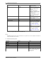
1
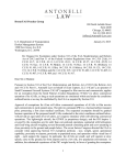
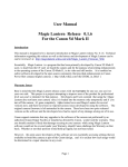
DJI VSM User Guide
UgCS 2.6.707
Copyright © 2015, Smart Projects Holdings Ltd
ii
CONTENTS
Contents
1
Connecting DJI autopilots to UgCS
1
1.1
Supported autopilots
. . . . . . . . . . . . . . . . . . . . . . . . . . . . . . . . . . . . . . . . .
1
1.2
First time vehicle connection . . . . . . . . . . . . . . . . . . . . . . . . . . . . . . . . . . . . .
1
1.3
Mission execution specifics . . . . . . . . . . . . . . . . . . . . . . . . . . . . . . . . . . . . . .
2
1.4
Command execution specifics . . . . . . . . . . . . . . . . . . . . . . . . . . . . . . . . . . . . .
3
1.5
Command availability . . . . . . . . . . . . . . . . . . . . . . . . . . . . . . . . . . . . . . . . .
4
1.6
Telemetry information specifics . . . . . . . . . . . . . . . . . . . . . . . . . . . . . . . . . . . .
4
1.7
Fail-safe actions . . . . . . . . . . . . . . . . . . . . . . . . . . . . . . . . . . . . . . . . . . . .
4
1.8
Waypoint turn types . . . . . . . . . . . . . . . . . . . . . . . . . . . . . . . . . . . . . . . . . .
5
1.9
General Purpose servo action setup . . . . . . . . . . . . . . . . . . . . . . . . . . . . . . . . .
5
1.9.1
Configuring trigger_action parameters in vsm-dji.conf . . . . . . . . . . . . . . . . . . . .
6
1.10 GoPro video link . . . . . . . . . . . . . . . . . . . . . . . . . . . . . . . . . . . . . . . . . . . .
6
1.11 Configuration file
. . . . . . . . . . . . . . . . . . . . . . . . . . . . . . . . . . . . . . . . . . .
6
1.11.1 Common parameters . . . . . . . . . . . . . . . . . . . . . . . . . . . . . . . . . . . . .
7
1.11.2 Serial port configuration
. . . . . . . . . . . . . . . . . . . . . . . . . . . . . . . . . . .
7
1.11.3 Waypoint turn type . . . . . . . . . . . . . . . . . . . . . . . . . . . . . . . . . . . . . .
7
1.12 Common configuration file parameters . . . . . . . . . . . . . . . . . . . . . . . . . . . . . . . .
7
1.12.1 UgCS server configuration . . . . . . . . . . . . . . . . . . . . . . . . . . . . . . . . . .
7
1.12.2 Logging configuration . . . . . . . . . . . . . . . . . . . . . . . . . . . . . . . . . . . . .
8
1.12.3 Serial port configuration
8
. . . . . . . . . . . . . . . . . . . . . . . . . . . . . . . . . . .
1.12.4 Network connection configuration
2
. . . . . . . . . . . . . . . . . . . . . . . . . . . . . .
9
1.12.5 Mission dump path . . . . . . . . . . . . . . . . . . . . . . . . . . . . . . . . . . . . . .
10
1.12.6 Automatic service discovery . . . . . . . . . . . . . . . . . . . . . . . . . . . . . . . . .
10
1.12.7 Proxy configuration . . . . . . . . . . . . . . . . . . . . . . . . . . . . . . . . . . . . . .
11
Disclaimer
11
Copyright © 2015, Smart Projects Holdings Ltd
1 Connecting DJI autopilots to UgCS
1
1
Connecting DJI autopilots to UgCS
See Disclaimer.
1.1
Supported autopilots
This document relate to the following DJI autopilots and ready to fly vehicles:
• A2
• Wookong-M
• Naza-M V2
• Phantom 2
For Phantom 2 Vision+, Phantom 3 and Inspire1 please see separate documents on http://ugcs.com site.
1.2
First time vehicle connection
Please follow these steps to connect a DJI vehicle to the UgCS:
1. To connect DJI vehicle to UgCS you need the 2.4Hz datalink ((http://www.dji.com/product/2-4g-bluetooth-da
or 900MHz datalink. Direct USB cable to DJI vehicle cannot be used to connect it to UgCS.
2. For Windows setup you also need to download from DJI site and install driver for 2.4GHz datalink
(http://download.dji-innovations.com/downloads/driver/DJI_WIN_Driver_Installer.exe). For 900MHz datalink download and install this package (http://download.-
dji-innovations.com/downloads/driver/DJI_Datalink_Driver_Installer_1.0.zip). This step is not required if you are running UgCS on Linux or Mac.
3. Before connecting the vehicle to UgCS, please ensure all autopilot settings (fail-safe, control mode switch,
compass calibration) are configured accordingly via DJI Assistant software. Please consult user manual of
your autopilot for details.
4. Once the drone is connected it should appear in vehicles list. Both Uplink and Downlink connections should
be available. Press Gain control and Edit to select corresponding vehicle profile and change the default
vehicle name to be convenient for you:
Copyright © 2015, Smart Projects Holdings Ltd
2
CONTENTS
Figure 1: New DJI vehicle
Vehicle profile needs to be assigned to allow mission planning with this vehicle. Image needs to be assigned
to see vehicle location on the map.
1.3
Mission execution specifics
• Fail-safe settings in mission properties are ignored.
• DJI has the following default fail-safe settings:
Condition
On GPS signal loss
Behavior
Land
On RC signal loss
Return to launch position
On low battery
Land
Notes
Happens when there are less
than 6 satellites visible for more
than 20 seconds
Default altitude is 20m. See
autopilot User Manual for more
information.
See autopilot User Manual for
more information.
• Please use DJI Assistant software to control the failsafe settings of autopilot.
• Mission waypoint actions supported by DJI:
Flight plan element / action
Camera control
Camera trigger
Support
No
Yes
Notes
Only Single-shot camera mode
is supported for A2 and
Wookong autopilots when
camera trigger is wired to
General Purpose servo output
see General Purpose servo
action setup for details.
Copyright © 2015, Smart Projects Holdings Ltd
1.4
Command execution specifics
3
Wait
Yes
Yaw
Partial
Land
No
Panorama
Point Of Interest
Camera by time
No
No
Yes
Camera by distance
Yes
Only one wait action per
waypoint is allowed.
1) Only when hovering over the
waypoint. Vehicle will always fly
with nose pointing to next
waypoint.
2) Only 1 Yaw action per
Waypoint is supported. (In case
of multiple yaw actions the last
one will be used.)
3) For Yaw action to succeed it
must be used together with
"Wait" action.
Vehicle will hover over the last
waypoint until operator takes
over the control.
Supported for A2 and Wookong
autopilots when camera trigger
is wired to General Purpose
servo output see General
Purpose servo action setup for
details.
Supported for A2 and Wookong
autopilots when camera trigger
is wired to General Purpose
servo output see General
Purpose servo action setup for
details.
• Mission can be uploded while vehicle is armed (in the air).
Warning
Uploading mission in the air is not recommended as it is possible to lose track of altitudes and "Return to
Launch" functionality can be affected.
1.4
Command execution specifics
Command
ARM
DISARM
AUTOMODE
MANUALMODE
CLICK-GO
HOLD
CONTINUE
RETURNHOME
Copyright © 2015, Smart Projects Holdings Ltd
Support
No
No
Yes
No
No
No
No
Yes
Notes
Take off and start the mission
Vehicle will fly to preconfigured
altitude (default is 20m) and return
to launch position and land. See
warning below.
4
CONTENTS
TAKEOFF
LAND
EMERGENCYLAND
CAMERA_TRIGGER
No
No
No
Yes
Trigger camera shutter. See
General Purpose servo action
setup for details.
Warning
WKM and NAZA autopilots sometimes ignore the "Return to home" command after mission is uploaded while
the vehicle is armed (in the air).
Note
If vehicle does not move after successful "Auto mode" command please verify that you have uploaded the
route to the vehicle. You can do that by checking log entries.
1.5
Command availability
UGCS Client can show command buttons in different shades. You can always press all buttons disregarding of
shade. Highlighted buttons suggest recommended commands, depending on vehicle current status.
Command availability:
State
Armed
Disarmed
1.6
Button highlighted
AUTOMODE,
CAMERA_TRIGGER,
RETURNHOME
AUTOMODE,
CAMERA_TRIGGER,
RETURNHOME
Button shaded
Telemetry information specifics
• Vehicle state (armed/disarmed) is controlled from RC transmitter. (Vehicle is armed automatically when "Auto
Mode" command is issued)
• Flight mode meaning
– Auto: Vehicle is executing mission or is returning to launch position.
– Manual: Vehicle is holding position.
Note
User can take over the control from any mode at any time by flipping the "Mode Switch" on RC transmitter
from "GPS" to "ATTI" to "GPS"
Sometimes DJI autopilot can report mode as "Manual" but cannot be controlled via RC transmitter. To take
over the control please flip the "Mode Switch" on RC transmitter to gain manual control.
1.7
Fail-safe actions
Fail-safe actions can be set only in DJI Assistant software.
Copyright © 2015, Smart Projects Holdings Ltd
1.8
Waypoint turn types
1.8
Waypoint turn types
5
There are 3 different routing planning modes for DJI autopilots: fixed-point turn mode (Stop and Turn), coordinated
turn mode (Bank Turn) and adaptive coordinated turn mode (Adaptive Bank Turn). You can choose turn type for
each Waypoint, Circle, Perimeter. The default turn mode in the system is Stop and turn.
Figure 2: Turn type
Turn type
Stop and Turn
Support
Yes
Bank Turn
Yes
Adaptive Bank Turn
Yes
Notes
Aircraft flies to the first fixed point
accurately, stays at the fixed point
and then flies to the next fixed
point.
The route of aircraft is calculated
with turning speed and turning
angle. The aircraft would fly from
one point to another point without
stopping.
It is almost the same performance
with Bank Turn mode. But the flight
routine will be more accurately
detailed with a planned flight
routine in this mode.
You can find more information about turning mode and supporting autopilots on the site http://wiki.dji.-
com/.
1.9
General Purpose servo action setup
DJI A2 and Wookong autopilots support general purpose servo action. It can be used to trigger camera.
You will need a device which can trigger camera remotely. Possible solutions:
• Gimbal with with camera trigger connector built in which supports PWM signal. (For example: Zenmuse Z15)
• Stand alone device to trigger camera via PWM signal (For example: http://copter.ardupilot.-
com/wiki/common-pixhawk-auto-camera-trigger-without-chdk/#22_IR_trigger_device)
Steps to configure camera trigger for use with UgCS mission flight:
• connect gimbal or triggering device to general purpose servo output on autopilot:
– A2: output "F2"
– Wookong: output "F1"
Copyright © 2015, Smart Projects Holdings Ltd
6
CONTENTS
(Consult DJI autopilot manual for more details on how to use GP servo outputs.)
• configure the servo action in configuration file. Add the "vehicle.dji.trigger_action" parameter to vsm-dji.conf,
see Configuring trigger_action parameters in vsm-dji.conf below.
• create a mission with waypoint actions Camera-mode Single-shot.
1.9.1
Configuring trigger_action parameters in vsm-dji.conf
Parameter trigger_action accepts seven comma separated integers.
Parameter number
1
2
3
4
5
6
7
Range
-1000..1000
-1000..1000
0..9
-1000..1000
0..9
-1000..1000
0..9
Description
Default servo position
1st servo position on action
seconds to hold 1st servo position
2nd servo position on action
seconds to hold 2nd servo position
3rd servo position on action
seconds to hold 3rd servo position
If your trigger needs only 1 servo position change then last 4 parameters can be omitted.
Example:
The following line in vsm-dji.conf:
vehicle.dji.trigger_action = 100, -200, 1
Produces the behavior:
• Autopilot will keep the GP servo at position 100 during the whole mission.
• On each waypoint which has the "Camera-mode: Single-shot" action the connected servo will:
– move to position -200,
– wait 1 second,
– move back to position 100.
1.10
GoPro video link
Vehicle can be configured to carry GoPro camera. In that case live video stream can be obtained via UgCS video
streamer component which must be running on the host which is connected to GoPro WiFi access point.
1.11
Configuration file
Default configuration file of the DJI VSM suits most needs and it is generally not necessary to modify it.
Configuration file location:
• On Microsoft Windows:
C:\Program Files (x86)\UgCS\bin\vsm-dji.conf
• On GNU/Linux:
/etc/opt/ugcs/vsm-dji.conf
• On Apple OS X:
/Users/[user name]/Library/Application Support/UGCS/configuration/vsm-dji.conf
Copyright © 2015, Smart Projects Holdings Ltd
1.12
Common configuration file parameters
1.11.1
7
Common parameters
All VSMs share a common set of configuration file parameters described in Common configuration file parameters.
DJI VSM configuration file prefix is:
vehicle.dji
1.11.2
Serial port configuration
Mandatory. This is the serial port name which appears when 2.4GHz or 900MHz datalink USB cable is plugged in.
At least one serial port definition should be present, otherwise VSM will not try to connect to the vehicle.
• Name: vehicle.dji.serial_port
• Description: Serial port configuration, for more details see Serial port configuration. Default DJI port communication speed is 115200 bps.
• Example:
vehicle.dji.serial_port.1.name = com1
vehicle.dji.serial_port.1.baud = 115200
1.11.3
Waypoint turn type
Optional. Used to override the turn type for all waypoints in uploaded mission. Please see DJI GS manual for
detailed explanation of turn types.
• Name: vehicle.dji.turn_type_override
• Pssible values: stop, bank, adaptive_bank
• Default: stop
• Example:
vehicle.dji.turn_type_override = adaptive_bank
1.12
Common configuration file parameters
VSM configuration file is a text file specified via command line argument - -config of the VSM application. Example:
--config /etc/opt/ugcs/vsm-ardupilot.conf
Each configuration parameter is defined as a line in the configuration file with the following structure:
name1.name2....nameX = value
where name1, name2 ... nameX are arbitrary names separated by dots to divide a variable into logical blocks and
a value which can be a number value or a text string depending on the context. See below the description about
common VSM configuration parameters.
1.12.1
1.12.1.1
UgCS server configuration
Listening address
Mandatory.
• Name: ucs.local_listening_address = [IP address]
• Description: Local TCP address to listen for incoming connections from UgCS server. Specify 0.0.0.0 to
listen from all local addresses.
• Example: ucs.local_listening_address = 0.0.0.0
Copyright © 2015, Smart Projects Holdings Ltd
8
CONTENTS
1.12.1.2
Listening port
Mandatory.
• Name: ucs.local_listening_port = [port number]
• Description: Local TCP port to listen for incoming connections from UgCS server. Default is 5556.
• Example: ucs.local_listening_port = 5556
1.12.2
1.12.2.1
Logging configuration
Level
Optional.
• Name: log.level = [error|warning|info|debug]
• Description: Logging level.
• Default: info
• Example: log.level = debug
1.12.2.2
File path
Optional.
• Name: log.file_path = [path to a file]
• Description: Absolute or relative (to the current directory) path to a logging file. Logging is disabled if logging
file is not defined. File should be writable. Backslash should be escaped with a backslash.
• Example: log.file = /var/opt/ugcs/log/vsm-ardupilot/vsm-ardupilot.log
• Example: log.file = C:\\Users\\John\\AppData\\Local\\UGCS\\logs\\vsm-ardupilot\\vsm-ardupilot.log
1.12.2.3
Maximum single file size
Optional.
• Name: log.single_max_size = [size]
• Description: Maximum size of a single log file. When maximum size is exceeded, existing file is renamed
by adding a time stamp and logging is continued into the empty file. [size] should be defined as a number
postfixed by a case insensitive multiplier:
– Gb, G, Gbyte, Gbytes: for Giga-bytes
– Mb, M, Mbyte, Mbytes: for Mega-bytes
– Kb, K, Kbyte, Kbytes: for Kilo-bytes
– no postfix: for bytes
• Default: 100 Mb
• Example: log.single_max_size = 500 Mb
1.12.3
Serial port configuration
Optional. VSM which communicates with vehicles via serial ports should define at least one serial port, otherwise
VSM will not try to connect to the vehicles. Port name and baud rate should be both defined. [prefix] is unique for
each VSM.
Copyright © 2015, Smart Projects Holdings Ltd
1.12
Common configuration file parameters
1.12.3.1
9
Port name
Optional.
• Name: [prefix].[port index].name = [regular expression]
• Description: Ports which should be used to connect to the vehicles by given VSM. Port names are defined
by a [regular expression] which can be used to define just a single port or create a port filtering regular
expression. Expression is case insensitive on Windows. [port index] is a arbitrary port indexing name.
• Example: vehicle.ardupilot.serial_port.1.name = /dev/ttyUSB[0-9]+|com[0-9]+
• Example: vehicle.ardupilot.serial_port.2.name = com42
1.12.3.2
Port baud rate
Optional.
• Name: [prefix].[port index].baud.[baud index] = [baud]
• Description: Baud rate for port opening. [baud index] is an optional arbitrary name used when it is necessary
to open the same serial port using multiple baud rates. [port index] is an arbitrary port indexing name.
• Example: vehicle.ardupilot.serial_port.1.baud.1 = 9600
• Example: vehicle.ardupilot.serial_port.1.baud.2 = 57600
• Example: vehicle.ardupilot.serial_port.2.baud = 38400
1.12.3.3
Excluded port name
Optional.
• Name: [prefix].exclude.[exclude index] = [regular expression]
• Description: Ports which should not be used for vehicle access by this VSM. Port names are defined by a
[regular expression] which can be used to define just a single port or create a port filtering regular expression.
Filter is case insensitive on Windows. [exclude index] is a arbitrary indexing name used when more than one
exclude names are defined.
• Example: vehicle.ardupilot.serial_port.exclude.1 = /dev/ttyS.∗
• Example: vehicle.ardupilot.serial_port.exclude = com1
1.12.3.4
Serial port arbiter
Optional.
• Name: [prefix].use_serial_arbiter = [yes|no]
• Description: Enable (yes) or disable (no) serial port access arbitration between VSMs running on the same
machine. It is recommended to have it enabled to avoid situation when multiple VSMs try to open the same
port simultaneously.
• Default: yes
• Example: vehicle.ardupilot.serial_port.use_serial_arbiter = no
1.12.4
Network connection configuration
Optional. VSM which communicates with vehicles via network should define at least one network connection,
otherwise VSM will not try to connect to vehicles. [prefix] is unique for each VSM.
Copyright © 2015, Smart Projects Holdings Ltd
10
CONTENTS
1.12.4.1
Local IP-address for UDP
Optional.
• Name: [prefix].detector.[con index].udp_local_address = [IP-address]
• Description: Local IP-address to listen for incoming UDP packets on. Specify 0.0.0.0 if you want to listen on
all local addresses.
• Example: vehicle.ardrone.detector.1.udp_local_address = 0.0.0.0
1.12.4.2
Local UDP port
Optional.
• Name: [prefix].detector.[con index].udp_local_port = [port number]
• Description: Local UDP port to listen for incoming packets on.
• Example: vehicle.ardrone.detector.1.udp_local_port = 14550
1.12.4.3
Remote IP-address for UDP
Optional.
• Name: [prefix].detector.[con index].udp_address = [IP-address]
• Description: Remote IP-address to send outgoing UDP packets to.
• Example: vehicle.ardrone.detector.1.udp_address = 192.168.1.1
1.12.4.4
Remote UDP port
Optional.
• Name: [prefix].detector.[con index].udp_port = [port number]
• Description: Remote UDP port to send outgoing packets to.
• Example: vehicle.ardrone.detector.1.udp_port = 14551
1.12.5
Mission dump path
Optional.
• Name: [prefix].mission_dump_path = [path to a file]
• Description: File to dump all generated missions to. Timestamp is appended to the name. Delete the entry
to disable mission dumping. All directories in the path to a file should be already created.
• Example: vehicle.ardupilot.mission_dump_path = C:\\tmp\\ardupilot_dump
1.12.6
Automatic service discovery
VSM can respond to automatic service discovery requests form UgCS server.
When this parameter is not configured, service discovery is disabled.
Optional.
• Name: service_discovery.vsm_name = [Service name]
• Description: Human readable service name.
• Example: service_discovery.vsm_name = Ardupilot VSM
Copyright © 2015, Smart Projects Holdings Ltd
2 Disclaimer
1.12.7
11
Proxy configuration
Optional. VSM is able to communicate with vehicle via proxy service which redirects dataflow received from vehicle
through TCP connection to VSM and vice versa using specific protocol. In other words proxy service appears as
a router between vehicle and VSM. At the moment there is one implementation of proxy in UgCS called XBee
Connector which retranslates data from ZigBee network to respective VSM.
1.12.7.1
IP-address for proxy
Optional.
• Name: [prefix].tcp.[con index].proxy = [IP-address]
• Description: IP-address to connect proxy to. Specify local or remote address.
• Example: vehicle.ardupilot.tcp.1.proxy = 127.0.0.1
1.12.7.2
TCP port for proxy
Optional.
• Name: [prefix].tcp.[con index].port = [port number]
• Description: TCP port to be connected with proxy through. Should be the same as in congiguration on proxy
side.
• Example: vehicle.ardupilot.tcp.1.port = 5566
2
Disclaimer
DISCLAIMER OF WARRANTIES AND LIMITATIONS ON LIABILITY.
(a) SMART PROJECTS HOLDINGS LTD MAKE NO REPRESENTATIONS OR WARRANTIES REGARDING THE ACCURACY OR COMPLETENESS OF ANY CONTENT OR FUNCTIONALITY OF THE PRODUCT AND ITS
DOCUMENTATION.
(b) SMART PROJECTS HOLDINGS LTD DISCLAIM ALL WARRANTIES IN CONNECTION WITH THE PRODUCT,
AND WILL NOT BE LIABLE FOR ANY DAMAGE OR LOSS RESULTING FROM YOUR USE OF THE PRODUCT.
INCLUDING BUT NOT LIMITED TO INJURY OR DEATH OF USER OR ANY THIRD PERSONS OR DAMAGE TO
PROPERTY.
(c) THE SOFTWARE IS SUPPLIED AS IS WITH NO WARRANTIES AND CAN BE USED ONLY AT USERS OWN
RISK.
Copyright © 2015, Smart Projects Holdings Ltd