1
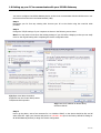
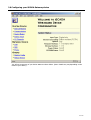
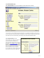
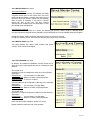
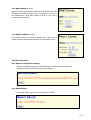
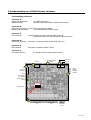
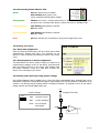
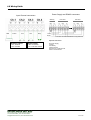
User Manual
2nnn.1002 Series
Version 1.3 / 05
1 of 10
1.0 Setting up your PC to communicate with your iSCADA Gateway
You have to configure the iSCADA Gateway device so that it can communicate with the iSCADA server over
the Internet from the site’s Local Area Network (LAN).
Step 1:
Disconnect your PC from any existing LAN. Connect your PC to the device using the cross-link cable
provided.
Step 2:
Change the TCP/IP settings of your computer as shown in the following screen shots.
Note: You may want to note down the existing settings of your PC before changing so that you can easily
revert to the original setting after completing the device configuration task.
2(a) Open Local Area Connection
Properties from the Control Panel, Select
TCP/IP and click Properties
2(b) Enter the IP address as shown above,
and then click OK
Step 3:
Power up the device, wait a few moments for it to initialize. LED#5 on the device should be ON, and all
other LEDs OFF. Open your browser and point it to 192.168.1.180 (this is the factory default IP setting for
all iSCADA Gateway devices) to begin the device configuration.
2 of 10
2.0 Configuring your iSCADA Gateway device
You will see a summary of your device status as shown below. (Note: Details may vary depending on the
model of your device).
3 of 10
2.1 SYSTEM CONFIG menu
2.1.1 Internal Modem sub menu (Not available for models without built-in modems)
You may store two sets of ISP dial up account information in your gateway. By default, it will connect to
your ISP using ISP1 account, failing which it will attempt to connect using your backup ISP account ISP2.
If you have only one set of ISP account, ensure that you enter the same information in ISP2.
2.1.2 Communication sub menu
These settings are used by the device to
communicate with the iSCADA server.
Using the default settings shown, the device
will obtain the IP address of the iSCADA
located at www.devicesworld.net server
from the DNS, failing which it will attempt to
bypass the DNS and connect directly to the
server’s IP address at 203.115.229.162.
Do not change any of these settings unless
instructed by Devices World’s support staff.
4 of 10
2.1.3 Device Master sub menu
Auto Connect Interval
In the absence of any activity, the Gateway will make
a System Check report to the server every 24 hrs to
confirm that the system is working fine end-to-end. If
the server does not receive a report from the Gateway
after 24 hours of inactivity, it will send a "System
Check Fail" alert to the user. The Auto Connect
Interval can be changed from this web page or from
the iSCADA client-side program.
Auto Disconnect Interval
In the absence of any activity for 1 minute, the Gateway will go from “Active” mode to “Standby Mode”.
The Auto Disconnect Interval can be changed from this web page or from the iSCADA client-side program.
During the “Active” mode, the device will poll the server once every 2 seconds
During the “Standby” mode, the device will poll the server once every 5 seconds.
2.1.4 Built-in Slave sub menu
This page displays the device serial number and model
number, which cannot be changed.
2.1.5 I/O Channels sub menu
By default, all channels are disabled. Use the combo box to
select the type of input signal that will be connected to each
channel.
For models 21nn
Channels 1-8 can be configured to take any of the following
signal type:Digital Signal:
0V=Low State, 5V=High State
Volt-free Contact: Open=Low State, Close=High State
Analogue Signal: 0-5V DC or 4-20mA
Channels 9&10 can be configured to take any of the following
signal type:Digital Signal:
0V=Low State, 5V=High State
Volt-free Contact: Open=Low State, Close=High State
For models 20nn
Channels 1-10 can be configured to take any of the following
signal type:Digital Signal:
0V=Low State, 5V=High State
Volt-free Contact: Open=Low State, Close=High State
Note: See I/O jumper settings in section 3.3 below.
Output channels 11&12 are N.O. relay contacts.
5 of 10
Any input channel configured as an Analogue channel will have the Analogue settings and Analogue
calibration values displayed at the bottom of the page.
These settings can only be changed from the client-side iSCADA program.
2.2 NETWORK CONFIG menu
2.2.1 LAN CONFIG sub menu
These settings enable the device to communicate within the
Local Area Network (LAN). Please check with your Network
Administrator how network devices (including PCs) are
managed on the network to which this device will be attached.
By default, your device is configured with a fixed local IP
address 192.168.1.180. Change this to the designated IP
address assigned by the Network Administrator. Enter the site’s
Internet Gateway IP address and Subnet Mask in the respective
fields.
If the network to which this device will be attached has a DHCP
server, enable the DHCP configuration using the combo box
and click “change”. The device will be assigned a local IP
address by the site’s DHCP server.
Important Notes:
1. If you need to enable the DHCP, this task should be done LAST, because after you click “Change”,
the device will no longer have a fixed IP and will no longer be able to communicate with your PC,
either via cross-link cable or through the LAN.
2. If you need to communicate with the device after enabling DHCP (or you have forgotten the fixed
IP address of any device), you can reset its network settings by pressing and holding down the
Reset button on the device (see section 3.2) until all the LEDs begin to blink. This will reset the
device’s LAN congiguration to the default IP address of 192.168.1.180 with DHCP disabled. This
action will only reset the network settings and will NOT affect all other settings in the device.
3. If the network to which this device is to be attached uses fixed local IP addresses (ie DHCP
disabled), and if the the default IP address 192.168.1.180 is available for the device, you may
attach this device to the network with its factory default LAN settings. However, if you are
attaching more than one device to the same network, make sure you assign a different IP address
to each device to prevent same IP adress conflicts.
6 of 10
2.2.2 DNS CONFIG sub menu
Enter the primary and secondary DNS server IP address here. This
information is needed when the device is configured to connect to
the iSCADA server using DNS instead of fixed IP (see Part A,
Communication sub menu).
2.2.3 PROXY CONFIG sub menu
If the LAN to which this device is attached has a proxy server,
enable the proxy configuration and enter the proxy settings here.
2.3 Other Tasks menu
2.3.1 Restore Configuration Settings
All your configuration and device data (like events, analogue data, etc) will be lost,
and device will be restored to factory default settings.
2.3.2 Reboot Device
Device will restart, with no loss of configuration or data.
7 of 10
3.0 Understanding your iSCADA Gateway Hardware
3.1 Identifying Connectors
Connector A:
Supply & Gnd terminals:
RS485 terminals:
12-24VDC input power
Shielded Twisted Pair cable to external slave devices
Connector B:
Signal Input terminals: 10 sets (see wiring guide for details)
Output Control terminals:
2 sets Normally Open Relay Contacts
Connector C:
RJ11 terminals:
Incoming telephone line for internal PSTN modem &
Outgoing connection for external phone sharing same line
Connector D:
RS232 DB9 connector: Connection to external modem (GSM, PSTN, UHF, etc)
Connector E:
RJ45 terminal:
Connection to Ethernet 10baseT (LAN)
Connector F:
LED status terminal:
For bringing 5 device status LEDs off board.
Ethernet
E
RS232 External
Modem
D
C
RJ11 Out
RJ11 In
F
LED
External
Connector
-
GND
-
RS485
+ Supply
+ RS485
A
Error
Ext. Modem
Int. Modem
Server Comm.
Power
ABC
Reset Button
B
Input Channels
1-5
Input Channels
6-10
Output
Channels
11 & 12
8 of 10
3.2 Understanding Status indicator LEDs
Power:
ON when device power is healthy
Slow Flashing when power is low
(when running on backup battery supply).
Server Comm:
Flashes once every 2 seconds when device is active online with iSCADA server
and once every 5 seconds when device is online with server in standby mode.
Internal Modem:
Fast blinking when dialing to Internet
ON when online
External Modem:
Fast blinking when dialing to Internet
ON when online
Error:
ON when internel error is detected or when power supply level is low.
3.2 Reseting your device
3.2.1 Reset LAN configuration
Press and hold the Reset button until all 5 LEDs start to blink
simultaneously. Release and wait a few moments for the
device to reset to default LAN setting as shown. (See section
2.2.1)
3.2.1 Reseting device to default configuration
The Reset button can also be used to restore your device to its
original factory settings. Power off the device, press and hold
down this button and turn on the power while holding down
the button. Release it when all 5 LEDs start to blink. See
section 2.0 to reconfigure your device.
3.3 Selecting input signal type using jumper settings
Your iSCADA Gateway device (Models 21nn) comes with fully programmable input channels that can be
individually configured to accept different types of input signals. Use the I/O Channels Configuration tools
(section 2.1.4) and the jumper settings below to configure channels 1-8. Channels 9 & 10 do not require
jumper settings, and accept digtal inputs only.
+5V
Jumper Settings
ABC
A&B:
Volt-free Contact
B&C:
4-20mA Analogue
None: 0-5V Analogue,
0/5V Digital
Analogue Front End
A
B
i/p
B
C
Gnd
9 of 10
4.0 Wiring Guide
Power Supply and RS485 connectors
Input Channel connectors
Gateway
Data P/S
Out
In
First Slave
Data Data
In
Out
*
+12V
4-20mA
0~5V
0/5V
Relay
Last Slave
P/S
In
Data Data
In
Out
P/S
In
*
9-24V
Supply
* 120 Ohm Termination Resistors for long data lines
Current Tx
Optional Accessories
+
Analogue inputs
Ch.1: 4-20mA
Ch 2: 0-5VDC
Digital inputs*
Ch.3: 0 or 5VDC
Ch 4: Volt-free contact
DC Power Supply
Charger
SLA Battery
Interface boards
Enclosure for multiple devices
Sensors & Transducers
Devices World Sdn. Bhd.
02S, 2330 Century Square, 63000 Cyberjaya
Tel: 603.8318.8660 | Fax: 603.8075.8050
[email protected] | www.devicesworld.net
10 of 10