1
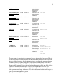
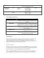
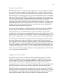
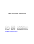
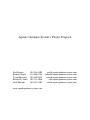
Aquatic Guidance System’s Project Proposal
Paul Hansen
Richard Wright
Tyson Ellsworth
Edward St. Louis
Nick Edwards
801-556-4509
435-406-1756
801-540-2539
801-718-1086
801-842-1502
www.aquaticguidancesystems.com
[email protected]
[email protected]
[email protected]
[email protected]
[email protected]
2
Abstract
How can a fisherman troll from a motorboat without simultaneously piloting the boat?
Our Aquatic Guidance System, with both conventional and auto-pilot steering, would
allow fishermen to concentrate on fishing. The challenge is to integrate automated
steering and throttle control with a graphical user interface (GUI)[2][3]. The GUI will
allow the user to control the boat, input commands, choose path specifications and set
speed. Sensor data will show readings for the boat’s tachometer[1], speedometer[1],
depth[5][6][7][8], compass[9], GPS data (current location, velocity, and heading)
[5][6][7][8], a 2D lake map with boat position, and estimated time of arrival.
For steering, throttle, and mechanical requirements, our team researched Kairos
Autonomi, a manufacturer of systems that enable vehicles to become autonomous[12].
For the GUI, our team chose the object-oriented programming language C#[2][3] which
is suitable for systems in which the computer is completely dedicated to the device it
controls. Our test platform is a 19.5 foot Bayliner Classic Motorboat. Beyond the sport of
fishing, our Aquatic Guidance System could be adapted for military, law enforcement,
commercial, and other recreational uses.
Motivation and Introduction
The motivation for this project is to design an autonomous boat that would provide many
benefits to our society. Many mundane tasks such as patrolling could be done by
computer. Lives could be spared by keeping human beings off of boats that would be sent
into dangerous situations. Unmanned waterskiing could become the next big recreational
pastime. And the idea that generated this automated boat concept in the first place,
hermits could troll and enjoy their fishing.
Other Possible Functions
•
Military: clearing unknown obstacles, removing explosives, routine patrolling,
hauling cargo and disabled boats, reconnaissance, attack, search and
rescue.
•
Law Enforcement:
•
Commercial:
•
Recreational: competition fishing, water-skiing.
routine patrolling, search and rescue.
hauling cargo, people transportation, towing barges and
disabled boats.
3
For the physical steering and throttle control, our team researched Kairos Autonomi, a
manufacturer of systems that enable vehicles to become autonomous. Kairos provided
our team with the Pronto4 Kit[12], which allows any vehicle that has a steering wheel to
be transformed into an autonomous vehicle. The kit provides autonomous use while not
interfering with the standard operation of the vehicle. Team member Richard, an
employee of Kairos, researched the mechanical requirements to retrofit the Pronto4 with
a 19.5 foot Bayliner Classic motorboat to control the steering and throttle digitally. The
Pronto4 Kit has built-in safety features including manual override and remote shut-off
capabilities.
For hardware and software issues we have all worked extensively with the elements that
will be needed to complete the project, including programming and hardware interfacing.
The following list details the exact features that will be implemented in this design.
Baseline Features
•
Pronto4 kit retrofitted to a 19.5 foot Bayliner Classic motorboat to control the
steering and throttle digitally.
•
Safety system including manual override, remote shut-off, and shore line
avoidance.
•
GUI for user to control the boat and input commands.
•
GUI display of a toolbar and menu.
•
GUI display of sensor data for the boat’s tachometer, speedometer, depth,
compass, GPS data (current location, velocity, and heading).
•
GUI display of 2D map of Strawberry Reservoir’s Renegade Bay indicating the
position of the boat.
•
GUI feature for user to specify the path of the boat and to set the speed, including
a display of the estimated time of arrival. .
•
Basic waypoint following capabilities
Extended Features
•
Ability to compensate for wind speed and direction.
•
3D model of the lake that allows the user to specify waypoints.s
•
LCD display for sensor data.
•
Advanced waypoint following, such as patrolling and depth following.
4
Project Demonstration
Due to the lack of a large body of water on campus, we will not be able to provide a
real-time demonstration at the University of Utah. Our presentation will consist of a
video demonstration of the motorboat operating in autonomous mode on Strawberry
Reservoir. Weather permitting, we plan to display the motorboat in the parking lot
nearest to the Demonstration Day activities on campus.
Project Tasks, Schedule Flow, Preliminary Risk Assessment, Risk Mitigation, and
Milestones:
Several milestones have been created to show significant progress on the project. These
milestones are listed below in the order in which we hope to have these elements of the
project finished.
Installation of the Pronto4 Kit onto the Bayliner Classic motorboat.
2-D (or possibly 3-D) lake model to be used with the user interface.
Completed GUI.
Successful extensive test of the pathing algorithm unit.
Sensors and Micro-Controller working correctly.
Lake Demo/Video
Below is a table showing individual tasks with the individuals assigned to those tasks and
milestones. Also shown is the scheduled completion dates and risk assessment.
Name
User Interface
Sensor Data Control
Tachometer
Speedometer
Compass
Time of Arrival
GPS Data
GPS Heading
GPS Location
GPS Velocity
*Wind Speed and
Direction
Menu Options
Start
End
Progress Assign To
2/26/07 5/26/07 0
Edward St. Louis,
Paul Hansen
2/26/07 5/12/07 0
Edward St. Louis,
Paul Hansen
4/10/07 4/17/07 0
Paul Hansen
2/26/07 4/10/07 0
Paul Hansen
2/26/07 3/20/07 0
Paul Hansen
2/26/07 3/31/07 0
Edward St. Louis
3/26/07 5/12/07 0
Edward St. Louis
3/26/07 5/5/07 0
Paul Hansen
4/23/07 5/5/07 0
Edward St. Louis
4/23/07 5/12/07 0
Edward St. Louis
3/20/07 4/18/07 0
Edward St. Louis
2/26/07 4/21/07 0
Risk Assessment
Low Risk
Low Risk
Low
Low
Low
Low
Low
Low
Low
Low
Low
Risk
Risk
Risk
Risk
Risk
Risk
Risk
Risk
Risk
Edward St. Louis, Low Risk
Paul Hansen
5
ToolBar
2/26/07 5/1/07
Map Control
2/26/07 5/26/07 0
0
Model of the Lake 2/26/07 5/26/07 0
Algorithms
5/7/07
Control Software
3/26/07 5/29/07 0
Safety Measures
5/29/07 6/16/07 0
Hardware
2/26/07 5/12/07 0
Pronto4 Kit
Installation
Sensors
4/9/07
6/30/07 0
5/12/07 0
2/26/07 5/12/07 0
MicroController
Sensor Interface
2/26/07 5/12/07 0
Tachometer
ADC
2/26/07 5/12/07 0
Speedometer
2/26/07 5/12/07 0
Compass
2/26/07 5/12/07 0
*Wind speed
and Direction
Sonar
3/12/07 5/12/07 0
GPS
3/12/07 5/12/07 0
2/26/07 5/12/07 0
Hardware/Software
Interface
4/16/07 6/30/07 0
Control Sensor GUI
5/28/07 8/31/07 0
Edward St. Louis,
Paul Hansen
Edward St. Louis,
Paul Hansen
Edward St. Louis,
Paul Hansen
Tyson Ellsworth,
Edward St. Louis,
Richard Wright,
Nick Edwards,
Paul Hansen
Tyson Ellsworth,
Edward St. Louis,
Richard Wright,
Nick Edwards,
Paul Hansen
Tyson Ellsworth,
Edward St. Louis,
Richard Wright,
Nick Edwards,
Paul Hansen
Tyson Ellsworth,
Richard Wright,
Nick Edwards
Tyson Ellsworth,
Richard Wright
Tyson Ellsworth,
Richard Wright,
Nick Edwards
Tyson Ellsworth,
Richard Wright,
Nick Edwards
Richard Wright,
Nick Edwards,
Paul Hansen
Tyson Ellsworth,
Edward St. Louis
Richard Wright,
Paul Hansen
Nick Edwards
Tyson Ellsworth,
Edward St. Louis
Tyson Ellsworth,
Edward St. Louis
Tyson Ellsworth,
Edward St. Louis,
Richard Wright,
Nick Edwards,
Paul Hansen
Tyson Ellsworth,
Low Risk
Medium Risk
Low Risk
Medium Risk
Medium Risk
Low Risk
Medium Risk
Low Risk
Medium Risk
Medium Risk
Medium Risk
Medium Risk
Medium Risk
High Risk
Medium Risk
Medium Risk
Medium Risk
Low Risk
6
Integration and Testing
Sensor GUI Integration 5/14/07 9/19/07 0
and Testing
6/4/07
Control Safety
Integration and Testing
6/23/07 0
6/25/07 7/14/07 0
Safety Pronto4
Integration and Testing
Lake Demo
9/24/07 10/13/07 0
Final Presentation and
Video Demo
Final Integration and
Testing
10/15/07 12/1/07 0
*LCD Display
Documentation
7/9/07
9/22/07 0
2/26/07 11/6/07 0
3/19/07 12/1/07 0
Edward St. Louis,
Richard Wright,
Nick Edwards,
Paul Hansen
Edward St. Louis,
Richard Wright,
Paul Hansen
Tyson Ellsworth,
Edward St. Louis,
Richard Wright,
Nick Edwards,
Paul Hansen
Tyson Ellsworth,
Edward St. Louis,
Richard Wright,
Nick Edwards,
Paul Hansen
Tyson Ellsworth,
Edward St. Louis,
Richard Wright,
Nick Edwards,
Paul Hansen
Nick Edwards
Tyson Ellsworth,
Edward St. Louis,
Richard Wright,
Nick Edwards,
Paul Hansen
Nick Edwards
Tyson Ellsworth,
Edward St. Louis,
Richard Wright,
Nick Edwards,
Paul Hansen
Low Risk
Low Risk
Low Risk
Medium Risk
Low Risk
Medium Risk
High Risk
Task coordinators
are in charge of
documentation for
each individual
task.
Low Risk
The map control is a medium risk component because of our lack of experience. The risk
for this component will turn low as Paul and Ed finish their Computer Vision course and
have the required expertise. The algorithms portion is a medium risk component because
of our inexperience in pathing algorithms; however, this will turn low as more time is
spent working on this component. The control software is a medium risk component
because of the interfacing issues with the hardware. Interfacing will be one of the last key
elements to become low risk because we need to develop the other tools first. The
hardware for sensors is also a medium to high risk component for our project because we
lack experience interfacing with sensors. The risk for the sensor hardware will drop as we
gain experience throughout the project.
7
The mitigation plan if the algorithms unit or the map control unit fails is to program in
certain paths without a dynamic plotting option available. The mitigation plan for the
sensors is having backup methods of controlling the boat in case we are unable to
interface other sensors. For example, if the compass doesn’t work then the GPS can be
used to make up the difference. This type of backup plan will not work for all of the
sensors. The sonar, GPS, and microcontroller will have to be made to work. These
components have been intensely studied and we are certain that interfacing these
components will not propose any problems that cannot be solved. To avoid failure in the
integration process we have spent a lot of time defining interfaces at the start of the
project so that potential problems can be avoided.
Complete Parts List with Vendor Information:
Part
Part Number
Supplier
Information
Pronto 4 Kit
Pronto 4 Kit
Fishing Boat
N/A
Richard’s
Dad
Tachometer
(ADC)
Built-in to
CSM-12C32
Freescale
Anemometer
(Pressure
Sensor)
Digital Compass
MPXH6250A
C6U
Freescale
R117COMPASS
Robot
Electronics
GPS and Sonar
Humminbird
Humminbir
d 383c
Microcontroller
Module
CSM-12C32
Freescale
Project Board
PBMCUSLK
Freescale
Kairos
Autonomi
Contact Information
Cost
Troy Takach
$0.00
Kairos Autonomi
(801) 255-2950
Orem, UT 84057
Richard’s Dad
$0.00
(435) 406-1048
Mona, UT 84645
Andy Mastronardi
$0.00
(Freescale University Relations)
[email protected]
Andy Mastronardi
$0.00
(Freescale University Relations)
[email protected]
Devantech Ltd (Robot Electronics) $52.00
Unit 2B Gilray Road
Diss, Norfolk, IP22 4EU
England
+44 (0)1379 640450
Richard’s Dad
$0.00
(435) 406-1048
Mona, UT 84645
Andy Mastronardi
$0.00
(Freescale University Relations)
[email protected]
$0.00
Andy Mastronardi
(Freescale University Relations)
[email protected]
Quantity
1
1
1
2
1
1
1
1
8
NMEA Cable
N/A
Home Brew
USB to Serial
Connector
N/A
Kairos
Autonomi
Laptop PC
Presario
R3000
Compaq
We will build this cable ourselves
(it will be a modified serial cable).
Troy Takach
Kairos Autonomi
(801) 255-2950
Orem, UT 84057
This is just Ed’s Computer
Edward St. Louis
(801) 718-1086
$5.00
1
$0.00
2
$0.00
1
List of Mentors and Resources:
Mentor/Resource
Troy Takach
Ken Stevens
Team Synapse
Richard’s Dad
Tom Henderson
Expertise
Creator of the Pronto 4 Kit and founder of Kairos
Autonomi. Can help us with Pronto 4 Kit issues and
funding.
Our senior project professor. Can help with all general
technical problems. Will guide us through the project by
making sure we are on track to deliver what we promised.
We often discuss issues with team Synapse to see if they
have run into similar problems. Can help us with
Microcontroller issues.
Owner of fishing boat and GPS/Sonar device. Can help
us with boat-related issues.
Computer vision professor. Can help us with issues in
our 3D software model of the lake. Also has expertise
with autonomous vehicle control.
Task Interfaces:
This project has several interfaces: an interface for the tachometer, an interface for the
compass, an interface for the sonar/GPS, an interface for the pressure sensors, a
microcontroller/computer interface, a computer/Pronto4 interface, and a graphical user
interface. These interfaces are described in this section.
Tachometer Interface
The purpose of this section is to accurately display the RPM of the engine on the GUI at
the laptop computer. We will be able to do this by interfacing with the tachometer of the
boat and sending values to the laptop through the microcontroller[1].
The way to obtain the RPM values is to tap into the signal sent from the engine to the
boat’s tachometer. It is assumed that this is some sort of voltage level, where higher
9
voltages represent higher RPMs and are displayed on the tachometer. The general idea is
to take this voltage signal and run it through an ADC which will output a digital value to
the control unit, which will then pass those values to the laptop. In the baseline design,
raw values are passed by the control unit, and the software running on the laptop will
convert those values into actual RPM measurements. By not converting to actual RPM at
the control unit, we can maintain a higher level of precision.
One possible modification would be to convert to RPM at the control level. The control
unit would be customized to the particular boat and ADC in use. This would make the
design more modular, since the software running on the laptop could rely on getting the
same range of values for the RPM, regardless of the boat/ADC type. However, that is
only a possible extension of the project and not the baseline. Either way, the RPM
measurement may be represented on the GUI either digitally, or as an analog display. A
flowchart of the system is shown below in the top figure.
VC
C
To ADC on
Microcontroller
Diagram Description:
In the upper-left corner of the lower diagram is a primitive picture of an outboard motor.
This is not an actual picture of the motor we will be using. On the right is a tachometer.
This is also not an actual picture of the tachometer we will be using. Below the
tachometer is an arrow pointing to the words, “To ADC on Microcontroller.” This
represents an analog signal going to an analog-to-digital converter on the microcontroller.
10
The motor sends an analog signal to the boat’s tachometer, representing higher RPMs by
a higher DC voltage. We have not yet measured this signal, but we are guessing that it
ranges from 0V to 12V. Since our Microcontroller can only manage a signal up to 5V, we
will include a voltage divider, as shown in the diagram. This should scale the signal down
to within 0V and 5V. This is a Medium-Risk point, since we are only taking an educated
guess as to the motor’s output voltage. But we are prepared to adapt whatever signal we
can get to the range that we need.
The microcontroller has 8 ADC ports on it. We will use one of these for the tachometer.
The ADC has 8-bit and 10-bit precision, which will give us either 256 or 1024 steps. If
the motor red-lines at about 7000 RPM, then the microcontroller will convert to a
precision level of either 28 or 7 RPMs. We have not yet determined if the increased
precision will outweigh the added cost of taking two bytes to communicate the RPMs to
the laptop, rather than a single byte.
Compass Interface Specification
The compass module[9] has pin outs as shown below in the figure below.
To power the compass sensor requires 5V power supply at 15 mA. To get the compass
reading out of the chip we are using the I2C interface provided by pins 2 and 3. That data
that comes from pins 2 and 3 is a 2 byte integer. This integer represents the compass
bearing as 0-3599 corresponding to 0-359.9 degrees. To get the compass bearing from the
sensor requires completing the following steps:
11
1. Send a start sequence
2. Send 0xC0 ( I2C address of the CMPS03 with the R/W bit low (even address)
3. Send 0x01 (Internal address of the bearing register)
4. Send a start sequence again (repeated start)
5. Send 0xC1 ( I2C address of the CMPS03 with the R/W bit high (odd address)
6. Read data byte from CMPS03
7. Send the stop sequence.
The bit sequence will look like this (on the next page):
Sonar/GPS
The sonar and GPS readings will be gathered using a Humminbird 383c fish finder unit.
Both the GPS data and the sonar reading are transmitted from the unit using the NMEA
(National Marine Electronics Association) standard protocol[5][6][7][8]. The NMEA
standard uses serial communications with the ASCII character set. The standard was
developed to have one device broadcast the data to multiple listening devices. As a result
of this design, no verification of receipt is required.
The NMEA protocol adheres to the following rules. First of all, each new message starts
with the '
$'character. The next five characters depict with type of message is being sent.
The data fields, which are comma delimited, depend on the type of message. An asterisk
immediately follows the data. Following the asterisk is a two-digit checksum to verify the
correct transmission of data. The configuration for the serial port is specified for a 4800
baud rate with 8 data bits with no parity and one stop bit.
The NMEA standard allows for multiple receivers to be connected to one sending unit. A
Humminbird 383c fish finder unit will be used as the sender. This will be connected to
the computer through a serial communications port. Only three types of messages are
needed in order to get the information that we need. One message provides data about the
latitude and longitude. Another provides velocity and heading information. A third type
of message gives the current depth of the boat. The following table contains the NMEA
acronyms for these messages as well as the format that the data fields will use.
12
Pertinent Data
Latitude
Longitude
Velocity
Heading
Depth
Message Type
$GPGLL
$GPGLL
$GPVTG
$GPVTG
$GPDPT
Data Format
dddmm.mm
dddmm.mm
kph
degrees
meters
Pressure Sensors
Digital pressure sensors[10] can be used in conjunction with a pitot tube in order to
determine the velocity of an object moving through a fluid. This is the same concept that
is used to determine the velocity of an airplane moving through the air. A pitot tube is
mounted on the underwater unit in the boat and will be connected to a digital pressure
sensor to determine the relative velocity of the boat moving through water.
The pressure sensor that was chosen is a sealed gauge sensor. This will provide an
absolute pressure value. There are two variables which will cause the pressure to vary.
First of all, the faster the boat moves through the water, the higher the pressure will be on
the sensor. The air pressure will also make a difference in the pressure felt. For example,
the pressure felt when the boat is stopped will be different in the ocean, at sea level, and
in a high-altitude lake. The true measure for our velocity is dependant upon the difference
between the pitot tube pressure and the standard air pressure. A second pressure sensor
that is exposed to the air will determine the barometric pressure of the environment.
The pressure sensors that will be used are produced by Freescale. Since this is the same
company that is supplying the microcontroller, there is relatively little risk involved with
the integration between these sensors and the microcontroller. The value will be read by
connecting the Vout pins to ADC pins on the microcontroller. A picture of the pressure
sensor is shown below.
Part # MPXH6250AC6U
13
Microcontroller/Computer Interface
The microcontroller we have selected (Freescale MC9S12C32)[1] has a built-in serial
communications port (DB9). This port is designed to load programs into the flash
memory on the chip. The pins of this port, however, are also accessible through the
software running on the device. As such, we will be sending sensor data to the computer
from the microcontroller via this serial port. The computer (laptop) that will be talking to
the microcontroller does not have a standard DB9 serial port with which to communicate.
To avoid writing software to make the microcontroller communicate via the USB port on
the laptop, we are purchasing a simple USB to serial converter. Windows drivers already
support the USB to serial converter. We will thus be able to talk with the microcontroller
through standard serial communication.
We will be using standard RS232 protocol[1] in transferring data packets between
devices. Two-way communication will be necessary as we are implementing a polling
program on the laptop. The laptop will send a request for the sensor data, and the
microcontroller will respond with all of the latest data it has collected from the sensors.
Because high bandwidth is not necessary, we will be using a half-duplex SCI
(asynchronous) communications scheme. Both the transmit (Tx) and receive (Rx) pins
can be shorted together; only a single data line is actually necessary to connect the two
devices. For simplicity we will use a standard serial cable which does not short the Tx
and Rx pins. Operation will be the same without shorting the pins as it would be with the
two pins shorted to a single data pin.
Using the RS232 protocol, we will send a total of 11 bits for each byte of data
transferred. One start bit will be followed by the eight data bits, after which a parity and
stop bit will be transmitted. The parity bit is optional in the protocol, but we would like to
be able to detect erroneous transfers.
The data transferred from the microcontroller to the computer is simple. We have
developed our own communications protocol tailored to the needs of what we will be
transferring. The data will be sent in three-byte chunks. The first byte will tell the
computer which sensor’s information will follow. The second and third byte will be a 16bit raw sensor value. Since there will only be a maximum of five sensors connected to the
microcontroller, there are only five sensor identification bytes. These values are shown in
the table below. With this protocol we maintain the ability to expand from five sensors up
to 2^8 (256) different sensors.
ASCII
HexBinary-Value
Sensor
Character
Value
0x56
0101 0110
“Velocity” from the anemometer
‘V’
0x54
0101 0100
“Tachometer” from the motor’s
‘T’
tachometer
0x43
0100 0011
“Compass” from the digital compass
‘C’
0x57
0101 0111
“Wind speed” from the wind sensor
‘W’
0x44
0100 0100
“Direction” from the wind sensor
‘D’
14
Computer/Pronto4 Interface
The Pronto4 kit[12] was developed to give programmers access to the physical control of
any vehicle. In order to communicate with various pieces of software, shared variables
have been used in the past. These shared variables reside in memory and can be accessed
by different processes running on the same processor. The Pronto4 kit is also compatible
with the recently developed JAUS (Joint Architecture for Unmanned Systems) protocol.
The JAUS protocol specifies a communication protocol that makes it convenient to share
messages between different computers and various sensor devices. We will take
advantage of the shared variables in order to communicate with the kit. A program called
djDrivenByWire converts the shared variables to a serial stream that is output directly to
the Pronto4 kit. The actual protocol that is used is described in a private, unpublished
document to which we have been given access.
Access to the shared variables is available through a dll that was developed by Edelwise
Inc. This dll provides function calls that allow software to dynamically allocate and
modify values that are stored in the memory used by the dll. These values are then
available to be read by any process running on that processor that is linked to the dll. The
dll provided by the company is not compatible with the C# programming language, so we
have created a wrapper class in C++ in order to provide access to the unmanaged dll[11].
Our current plan is to have all of the software run on one laptop. If we find that we need
more processing power in order to facilitate the smooth control of the boat or if the
shared variables need to be shared by multiple computers, a program called djSharedLink
uses a UDP connection to keep the different copies of the shared variables in agreement.
Using this approach, we can have the GUI and sensor-processing algorithms run on one
computer which outputs these values to a second computer. This second computer would
be devoted to the decision-making algorithms as well as outputting these shared variables
over its serial port to the Pronto4 kit.
Graphical User Interface (GUI)
For the GUI, our team chose the object-oriented programming language C# which is
suitable for embedded systems in which the computer is completely dedicated to the
device it controls. Using C#, we programmed the GUI to allow the user to control the
boat and input commands. The commands that the user will enter will consist of
waypoints that the user clicks on the 2D model of Renegade Bay, the type of path that the
boat will take between the waypoints, and the commands to start and stop the boat.
The GUI will display a toolbar and menu that help the user enter commands. The GUI
will display sensor data for the boat’s tachometer, speedometer, depth, compass, and GPS
data including current location, velocity, and heading. The sensor data is real-time data
and is updated constantly. The GUI will show the user a 2D map of Strawberry
15
Reservoir’s Renegade Bay indicating the position of the boat. The 2D map is a standard
topographical map.
The GUI will have a feature allowing the user to specify the path of the boat and to set
the speed of the boat. The user will also see a display of the estimated time of arrival. The
user can point and click on the map display to indicate where the boat should go by
choosing either particular points on the map or a path that follows a specified depth. The
GUI also lets the user define what kind of path to take. The path can follow a certain
depth of water between points, patrol between points, or just follow a straight shot
between the points.
Testing and Integration Strategy
The division of labor that we have developed will allow us to do most of the work in
parallel. The graphical user interface, sensor unit, and control unit can all be developed
independently. Interfacing these three components will be the most difficult process. In
order to complete our project in time, these three components will be completed by the
end of May. This will allow each of these portions of the project to be tested
incrementally and in parallel. For testing we will be able to do the vast majority of our
testing at school and not on the lake because each module can be tested apart from other
modules. The integration strategy is described in the task interfaces listed above.
Current Engineering Deliverables and Conclusion
To date, we have already had success in the development of the following components.
First of all, we have a working dll wrapper so that we can access the shared variables
from C#. We also have the skeleton code written for our GUI in C#. We have created a
digital 3D model of Strawberry Reservoir[4], which will be our main test site. We have
written code for the microcontroller which is able to read from an ADC port and send the
values across a serial port to a computer.
By retrofitting the Pronto4 Kit from Kairos Autonomi onto a 19.5 foot Bayliner Classic
motorboat and integrating our graphical user interface, we will provide fishermen the
option to troll for fish in Renegade Bay without the worry of piloting the boat. Our
Aquatic Guidance System will provide both conventional and auto-pilot steering with the
safety of manual override, remote shut-off, and shore line avoidance. The possibility
exists to extend our product by compensating for wind speed and direction, enhancing the
map function to 3D and adding an LCD display for sensor data. It is also feasible to
adapt our system for military, law enforcement, commercial, and other recreational uses.
16
Resources
Microcontroller:
[1]Valvano, Jonathan W. Embedded Microcomputer Systems. Ontario: Nelson, 2007.
C#:
[2]Sharp, John Microsoft Visual C# 2005 Step by Step. Microsoft Press, Redman
Washington, 2006.
[3]Duffy, Joe Professional .NET Framework 2.0. Wiley Publishing, Inc., Indianapolis,
Indiana. 2006.
Computer Vision:
[4]Forsyth, David A. and Ponce, Jean Computer Vision A Modern Approach. Pearson
Education, Inc., Upper Saddle River, New Jersey. 2003.
NMEA / GPS and Fishfinder:
[5]Humminbird 383c User Manual
[6]http://www.interfacebus.com/NMEA-2000_Standard.html , 2007.
[7]http://www.werple.net.au/~gnb/gps/nmea.html, 2007.
[8]http://www.gpsinformation.org/dale/nmea.htm, 2007.
Digital Compass:
[9]http://www.robot-electronics.co.uk/htm/cmps3doc.shtml, 2007.
Pressure Sensor:
[10]http://www.freescale.com/files/sensors/doc/data_sheet/MPXH6250A.pdf, 2007.
Pronto4 Kit:
[11]C Source Code Provided by Edelwise to access Shared Variables
[12]Unpublished technical document explaining interface protocol for Pronto4 kit