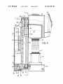
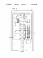
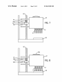
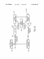
1
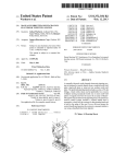
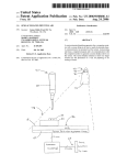
US008367022B2
(12) United States Patent
Warhurst et a].
(10) Patent N0.:
(45) Date of Patent:
US 8,367,022 B2
Feb. 5, 2013
UNINTENDED MOTION CONTROL FOR
MANUALLY DIRECTED MULTI-CHANNEL
ELECTRONIC PIPETTOR
5,116,180 A
5/1992 Fung et al.
5,895,630 A *
6,270,726 B1 *
4/1999
8/2001
6,360,792 B1
3/2002 GanZ et al.
(75) Inventors: Julian Warhurst, Ashland, MA (US);
6,627,446 B1 *
6,637,473 B2 *
(54)
Richard Cote, Bolton, MA (U S)
6,982,063 B2
(73) Assignee: Integra Biosciences Corp., Hudson, NH
(Us)
(*)
Notice:
Subject to any disclaimer, the term of this
patent is extended or adjusted under 35
9/2003
10/2003
Roach et a1. .................. .. 436/43
GanZ et al. .................. .. 141/130
l/2006 Hamel et al.
7,105,132 B2 *
7,135,146 B2 *
9/2006
11/2006
Shumate et al. ............ .. 422/510
Johnson et a1. ............. .. 422/521
7,540,205
7,662,343
7,662,344
8,033,188
6/2009
2/2010
2/2010
10/2011
Nelson et a1.
Mathus et al.
Mathus et al.
Kalmakis et al.
B2
B2
B2
B2
2001/0005489 A1 *
6/2001
U.S.C. 154(b) by 0 days.
Roach et a1. .................. .. 422/99
(Continued)
(21) Appl. N0.: 13/099,953
(22) Filed:
Skaborn et al. ............. .. 422/509
Tyberg et al. ............... .. 422/509
FOREIGN PATENT DOCUMENTS
WO
May 3, 2011
2009/130318
10/2009
OTHER PUBLICATIONS
(65)
Prior Publication Data
US 2011/0268628 A1
Nov. 3, 2011
Related US. Application Data
Rainin Pipetting 360°Simultaneous 96-Well pipetting, Fast manual
benchtop system, 2009 Rainin Instrument, LLC, PB-210 LIQ RevB,
2 pages.
(Continued)
(60) Provisional application No. 61/330,545, ?led on May
3, 2010.
Primary Examiner * Brian R Gordon
(51)
Int. Cl.
B01L 3/02
(52)
(2006.01)
US. Cl. ...... .. 422/509; 422/511; 422/516; 422/522;
422/524; 422/525; 73/863.32; 73/864; 73/864.01;
73/864.11; 73/864.24; 73/864.25
(58)
(74) Attorney, Agent, or Firm *Andrus, Sceales, Starke &
SaWall, LLP
Field of Classi?cation Search ................ .. 422/ 509,
422/511, 516, 519522, 524525, 63*681;
73/863.32, 864, 864.01, 864.11, 864.13,
73/864.16*864.21, 864.25, 864.31
See application ?le for complete search history.
(56)
References Cited
U.S. PATENT DOCUMENTS
4,478,094 A *
4,555,957 A *
10/1984
12/1985
Salomaa et a1. ......... .. 73/863.32
Frankel et a1. ........... .. 73/864.14
(57)
ABSTRACT
A manually directed, electronic multi-channel pipettor uses
servo controlled motors to drive a carriage and pipetting head
in response to a user’s manipulation of a control handle. The
pipetting head include an array of tip ?ttings, e.g. 96. The
system includes a check processor to avoid unintended
motion in case of system faults or crashes. The system
requires substantial force to attach the array of tips, and
therefore includes controls that require both of the user’s
hands be occupied during the tip attachment process.
8 Claims, 13 Drawing Sheets
US 8,367,022 B2
Page 2
US. PATENT DOCUMENTS
2001/0048899 A1 * 12/2001 Marouiss et a1‘ """""" " 422/100
2005/0249635 A1
11/2005
Okun et al.
OTHER PUBLICATIONS
Rainin Pipetting 360° Liquidator 96, Manual benchtop pipetting
. .
2006/0048846 A1
3/2006 Roenneburg
system, 2000 Ra1n1n Instrument, LLC, 9920-360 Rev. B, 16 pgs.
2007/0221684 A1
2009/0074622 A1
9/2007 Steinbrenner et a1‘
3/2009 Kalamakis et a1‘
CyB1-Well P1pettor User Manual, Release Sep. 2008, 88 pgs.
Thermo Scienti?c Matrix Hydra II, Product Speci?cation, 2008
2009/0226344 A1*
2009/02745g7 A1
9/2009 Nishida et a1. ................ .. 422/67
1 1/2009 ButZ et a1‘
Thermo Fisher Scienti?c, Inc» 2 PgS~
Thermo Scienti?c Matrix PlateMate 2x3, Product Speci?cation,
2011/0039709 A1*
2/2011 Lips et a1. ....................... .. 506/7
2007 Thermo Fisher Scienti?c, Inc‘, 2 pgs
2011/0209564 A1 *
9/ 2011 Von Beichmann
Thermo Scienti?c Matrix PlateMate Plus, Product Speci?cation,
et a1. ........................ ,, 73/864,01
2011/0268627 A1
11/2011 Warhurst et a1.
2011/0296931 A1
12/2011 Warhurst
2007 Thermo Fisher Scienti?c, Inc., 2 pgs.
* cited by examiner
US. Patent
Feb. 5, 2013
58
Sheet 1 0f 13
US 8,367,022 B2
,9?
28
20
FIG. 1
Q
16
US. Patent
54
56
58
24
Feb. 5, 2013
Sheet 2 0f 13
US 8,367,022 B2
US. Patent
Feb. 5, 2013
Sheet 3 0f 13
US 8,367,022 B2
56
58
12
32
US. Patent
Feb. 5, 2013
Sheet 4 0f 13
US 8,367,022 B2
30
22
FL
IW
74FL
76
I?_
f
102
\
100 )
8O
-3
US. Patent
Feb. 5, 2013
FIG. 5
Sheet 5 0f 13
US 8,367,022 B2
24
US. Patent
Feb. 5, 2013
Sheet 7 0f 13
US 8,367,022 B2
60
AW
60
204
FIG. 8
US. Patent
Feb. 5, 2013
Sheet 8 0f 13
US 8,367,022 B2
60
204
_/ 22
FIG. 9
%\
14
/2s
FIG. 10A /74'1O8
2 O 8A
M
HamEDWMPR wKm Lwm
F0
C
B
AI
PERMANENT
T N
MAGNET MOTOR
m
02m
HALL EFFECT
BIPOLAR SENSORS
2
MOTOR DIRECTION
AND POWER LEVEL
HALL EFFECT _
SIGNALS
_
COMUTATION
LOGIC
POWER
3 PHASE
MOTOR DRIVER I TO MOTOR
WINDINGS
US. Patent
Feb. 5, 2013
US 8,367,022 B2
Sheet 10 0f 13
I
READ 3 HALL INPUT
PINS INTO ONE BYTE
FAULT
CONDITION
EXISTS
7
WRITE INVALID HALL
CODE TO OUTPUT PINS
WRITE BYTE TO
3 OUTPUT PINS
I
I
GOTO LOCKOUT STATE
UNTIL REBOOTED
FIG. 11
SAFETY SWITCH
ACTIVATED
MEASURE MOTOR
TRAVEL USING ENCODER
ZERO THE
POSTION COUNTER
TRAVEL
YES
GOTO LOCKOUT STATE
UNTIL REBOOTED
FIG. 13
US. Patent
Feb. 5, 2013
CLOCKWISE
ENCODER COUNT
DETECTED
?
Sheet 12 0f 13
US 8,367,022 B2
YES
I
ADD 3 TO
ERROR COUNTER
NO
COUNTER
CLOCKWISE
ENCODER COUNT
DETECTED
YES
SUBTRACT 3 FROM
ERROR COUNTER
NO
CLOCKWISE
HALL MOTION
DETECTED
.7
YES
I
SUBTRACT 250 FROM
ERROR COUNTER
NO
COUNTER
CLOCKWISE
HALL MOTION
YES
I
ADD 250 TO
ERROR COUNTER
ENCODER
ERROR COUNT
YES
> +/ —500
I
?
NO
GOTO LOCKOUT STATE
UNTIL REBOOTED
FIG. 14
US. Patent
Feb. 5, 2013
ENCODER
MEASURED SPEED
>MAX ALLOWED
7
Sheet 13 0f 13
US 8,367,022 B2
L
GOTO LOCKOUT STATE
UNTIL REBOOTED
US 8,367,022 B2
1
2
UNINTENDED MOTION CONTROL FOR
MANUALLY DIRECTED MULTI-CHANNEL
ELECTRONIC PIPETTOR
using a levered mechanical mechanism. Because the system
is fully manual, it lacks the ability to program precise proto
cols and liquid transfer amounts. On the other hand, elec
tronic hand-held pipettors and automated liquid handling sys
tems can be programmed to aspirate a precise volume of
FIELD OF THE INVENTION
liquid reagent or sample and then dispense the aspirated vol
ume, sometimes as a series of equal volume aliquots in suc
The invention relates to a manually-directed, electronic
pipetting system having a multi-channel pipetting head With
a plurality of pipetting channels, e.g., 96-channels, arranged
cessive dispensing operations. Programmable electronic
hand-held pipettors and automated liquid handling systems
in an array of roWs and columns. In particular, the invention
can also be con?gured to do quite complex pipetting opera
tions, such as mixing, repeat pipetting, diluting, etc.
pertains to protecting against unintended motion, eg when
While programmable, automated liquid handling systems
attaching disposable pipette tips onto ?ttings of the pipetting
have many desirable features over a fully manual 96-Well
head or otherwise.
liquid transfer system, they are generally too large and expen
sive for certain laboratory applications. To address this issue,
the As signee of the present application has developed a manu
BACKGROUND OF THE INVENTION
ally directed, electronic multi-channel pipetting system hav
Multi Well-plates, also knoWn as microtiter plates or micro
Well-plates, are standard products in clinical and research
laboratories. A multi-Well plate is a ?at plate With multiple
Wells used as individual test tubes. The most common multi
ing a pipetting head With a plurality of pipetting channels
20
Well plates include 96-Wells or 384-Wells arranged in a rect
angular matrix. ANSI has set standardized dimensions and
arranged in a tWo-dimensional array of roWs and columns,
preferably 96-channels arranged in an array of 8 roWs and 12
columns correlating to a standard 96 Well-plate. The system is
described in Assignee’s co-pending patent application
SBS footprints for Well-plates. For example, a 96-Well plate
entitled “Manually-Directed, Electronic Multi-Channel
has 8 roWs and 12 columns of Wells centered 9 mm centerline
Pipetting System”, application Ser. No. 13/099,782,by Julian
to-centerline. A typical 384-Well plate includes 16 roWs and
25
Warhurst, Gary Nelson and Richard Cote, ?led on even date
hereWith, Publication No. US. 2011/0268627 A1, published
Nov. 3, 2011, and incorporated herein by reference. In the
24 columns of Wells With a centerline-to-centerline distance
of 4.5 mm. Multi Well-plates With 1536 Wells and higher are
also available. Some multi Well-plates are designed to hold
Assignee’s manually-directed, electronic 96-channel pipet
larger volumes than the standard multi Well-plate, yet main
ting system, the pipetting head is mounted to a movable
carriage that is attached to a toWer containing a drive system
for the pipetting head. A deck With at least one, but preferably
tWo or more, Wellplate nesting receptacles is located in front
of the toWer and is accessible by the pipetting head. The toWer
contains a drive system to raise and loWer the pipetting head
tain the standard centerline-to-centerline dimensions. These
Well-plates are taller and are commonly called deep Well
30
plates.
In a laboratory, multi Well-plates are ?lled With various
liquid samples, and it is routine to transfer liquid samples
from one Wellplate to another in order to implement as says or
35
store duplicate samples. It is also routine to transfer liquid
The Assignee’ s system also includes a control handle and a
menu-driven softWare programming interface that is the same
or quite similar to the control handle and programming inter
reagents or samples from a common reservoir to either a
standard multi-Well plate or a deep Well-plate. Often, hand
held, multi-channel pipettors, With 8, 12 or 16 disposable
pipette tips mounted thereto, are used to draW some or all of
the liquid from a set of Wells in one Wellplate and transfer
aliquots into another set of Wells in the same Wellplate or
40
see e.g., the disclosures in US. Pat. No. 7,540,205 entitled
45
Well-plates, automated liquid handling machines have been
developed to provide much higher throughput than a techni
cian, even one using a multi-channel pipettor. In the art, there
are several types of automated liquid handling machines to
automatically ?ll multi Well-plates. Such automated liquid
handling machines typically use sophisticated Cartesian
robots for positioning the disposable pipette tips, While shut
50
tling Well-plates from storage and into position for liquid
transfer. It is common for these automated liquid handling
machines to use removable and replaceable pipetting heads in
order to accommodate various siZed pipette tips.
Most of these automated liquid handling machines are
assigned to the Assignee of the present application and incor
porated herein by reference, now US. Pat. No. 8,033,188 B2,
issued Oct. 11, 2011. One of the bene?ts of the similarity is
that users comfortable With the Assignee’s hand-held pipet
ally assisted, electronic 96-channel pipetting system. In the
Assignee’ s 96-channel system, hoWever, the control handle is
mounted to a load cell attached to the carriage for the pipet
ting head. The load cell detects force exerted on the control
handle and outputs a corresponding signal to an electronic
60
motor control system. In use, the user grabs the control handle
in a manner similar as to When using a hand-held electronic
pipettor, and exerts pres sure on the control handle so that the
order to address this need, the prior art includes, e. g., a simul
taneous 96-Well manual pipetting system. This fully manual
system includes an array of pipette tip ?ttings matching the
dimensions of a standard 96 Well-plate, and aspirates and
patent application Ser. No. 11/856,231 by Gary E. Nelson,
George P. Kalmakis, Kenneth Steiner, Joel Novac, Jonathan
Finger, and Rich Cote, ?led on Sep. 17, 2007, and incorpo
rated herein by reference; and “Pipettor SoftWare Interface”,
application Ser. No. 1 1/ 856,232 by George P. Kalmakis, Gary
Nelson, Gregory Mathus, Terrence Kelly, Joel Novak, Ken
neth Steiner and Jonathan Finger, ?led Sep. 17, 2007,
tors are able to easily crossover to use the Assignee’s manu
55
rather expensive, and also quite large. Many include sophis
ticated computer control Which requires extensive training, as
Well as set up and programming. Such automated, high
throughput systems are not practical for some applications. In
face on hand-held electronic pipettors sold by the Assignee,
“Electronic Pipettor”, issuing on Jun. 6, 2009, based on US.
another Wellplate. Pipettors and pipette tips come in various
siZes in order to accommodate different volumes of liquid
transfer. In order to produce a high volume of prepared multi
to aspirate and dispense reagents or samples in the Well-plates
or reservoirs placed in the nesting receptacles.
electronic motor control system moves the pipetting head
relative to the Well-plates and reservoirs on the deck. In the
65
preferred embodiment, the toWer contains a motorized, Z-axis
dispenses liquid from 96-disposable pipette tips simulta
drive mechanism for vertically raising and loWering the pipet
neously. The pipette tips are mounted to the 96-tip ?ttings
ting head With respect to the Wellplate deck, and a motoriZed
US 8,367,022 B2
3
4
x-axis drive mechanism for moving the tower and pipetting
head laterally, both being driven in response to sensed force
of the carriage. The tip attach button may be located on
another part of the system, or may be located on the laboratory
exerted on the control handle. If the user presses on the
bench top.
The preferred method of attaching the disposable pipette
control handle from left to right, the toWer along With the
pipetting head moves from left to right. If the user pulls the
control handle upWard, or pushes doWnWard on the control
handle, the Z-axis drive mechanism raises or loWers the pipet
tips involves the folloWing steps. First, a tip rack full of
disposable tips is placed on one of the Wellplate nesting
receptacles on the deck. Then, using the control handle, the
pipetting head is loWered and aligned over the tip rack. Most
preferably, the electronic control system biases the pipetting
head into proper vertical alignment prior to alloWing the
pipetting head to descend doWnWard to insert the tip ?ttings
into the respective pipette tips. The preferred manner of bias
ing is described in co-pending patent application entitled
“Pipetting Tip Positioning for a Manually-Directed, Elec
ting head accordingly.
While Assignee’s manually directed, electronic 96-chan
nel pipetting system preferably incorporates the user inter
face and menu-driven softWare similar to Assignee’s single
channel and multi-channel, hand-held pipettors, other aspects
of a 96-channel pipetting system must be handled quite dif
ferently.
tronic Multi-Channel Pipetting System”, based on Us. Pro
visional Application No. 61/330,551, ?led on even date here
SUMMARY OF THE INVENTION
When attaching an array of 96-pipette tips simultaneously
to tip ?ttings on a pipetting head, the required cumulative
With, noW U.S. patent application Ser. No. 13/099,854, ?led
20
insertion force is signi?cantly greater than With a single chan
nel, hand-held pipettor or an 8-, 12- or 16-channel hand-held
pipettor. In accordance With the invention, the motoriZed,
vertical drive mechanism used to raise and loWer the pipetting
head is used to generate enough force for simultaneous inser
25
tion of 96-tip ?ttings into 96-disposable pipette tips. HoW
ever, such force is not necessary and not desirable under
normal operating conditions other than for tip attachment. In
one aspect of the invention, the system includes a detector
(eg a force detector) for the vertical drive mechanism that
generates a safety signal that is transmitted to the electronic
control system if the vertical drive mechanism meets unex
carriage for the pipetting head. At this point, the operation of
the servo control system is disabled and the tip attachment
cycle is ready for initiation. To do this, the user Will depress
the tip attach button With one hand and press doWnWard on the
control handle With the other hand. The pipetting head is
35
loWered a ?xed distance and held momentarily to ensure
attachment of the pipette tips. Then the pipetting head is
automatically lifted up to clear the tips from the tip box. At
safety trigger is overridden.
Another aspect of the invention recogniZes the desirability
that time, normal servo control is returned to the user.
of keeping the user’s hands free of the motor driven pipetting
head during the tip attachment process in order to protect the
user from injury. In this regard, the preferred embodiment of
the invention is implemented in a system having a multi
Preferably, the tip ?ttings and the pipette tips are the same
or similar to that described in Us. Pat. Nos. 7,662,343 and
7,662,344 both entitled “Locking Pipette Tip and Mounting
Shaft” by Greg Mathus, Terrence Kelly and Rich Cote, both
channel pipetting head With 96-tip ?ttings. The multi-channel
pipetting head is preferably carried in a carriage mounted to a
toWer. A deck is located beloW the pipetting head and is
pushes doWn on the control handle to loWer the tip ?ttings into
the pipette tip collars. The increased force load on the pipet
ting head should trip the safety sWitch to stop further doWn
Ward movement. The softWare checks that the tip ?ttings are
located in the proper location, height and lateral position for
the pipette tips of interest and then provides a signal to the
user, such as illuminating a tip attach button on the top of the
30
pected resistance. If triggered, the system stops the motor for
the vertical drive mechanism from further doWnWard move
ment. If a tip attachment sequence needs to be initiated, the
May 3, 2011, Publication No. U.S. 2011/0296931 A1, pub
lished Dec. 8, 2011, by Julian Warhurst, assigned to the
Assignee of the present invention and incorporated herein by
reference. Once the pipetting head is aligned With the tip
?ttings hovering over the respective pipette tips, the user
45
assigned to the Assignee of the present application and incor
porated herein by reference. The tip ?ttings described in these
patents provide substantial lateral stability for the attached
adapted to hold at least one multi-Wellplate or reagent reser
pipette tips. This enables the user to simultaneously touch off
voir, as Well as a tip tray full of an array of 96-pipette tips. A
the mounted pipette tips, e.g. 96-pipette tips, and remain
control handle, preferably mounted to the carriage for the
con?dent that the tips Will remain properly attached and
aligned on the tip ?ttings.
pipetting head, is held in the hand that the user normally uses
for pipetting. An electronic control system that moves the
pipetting head relative to the deck in accordance With the
direction and amount of force applied to the control handle, as
described in accordance With the above mentioned co-pend
ing patent applications. In accordance With this aspect of the
present invention, the system includes a tip attach button that
must be activated in order to continue loWering the pipetting
head to attach the disposable pipette tips to the tip ?ttings on
50
tended motion of the pipetting head. More speci?cally, in
accordance With the preferred embodiment of the invention,
55
60
the user’ s hands are occupied When the vertical drive mecha
nism loWers the pipetting head to insert the tip ?ttings into the
pipette tip collar, thereby preventing the opportunity that one
of the user’s hands be located in an unsafe location When the
tips are being attached. In accordance With the invention, it is
not necessary for the tip attach button to be located on the top
separate servo control loops are used to control the operation
of the X-axis horiZontal drive mechanism and Z-axis vertical
drive mechanism respectively. Each servo control loop pref
erably includes a check processor Which receives input sig
the pipetting head. As mentioned, the required tip insertion
force may be signi?cant. The tip attach button is preferably
located on the top of the carriage for the pipetting head, and
requires activation by the user’s other hand. In this manner,
Another aspect of the invention pertains to the use of a
check processor in the servo control system to prevent unin
65
nals from Hall-effect sensors associated With the respective
motor. Under normal operating conditions, the check proces
sor transmits to the motor driver an echo of the input signals
from the Hall-effect sensors. In the event that the check pro
cessor detects a fault condition in the operation of the motor
drive mechanism, the check processor Will not transmit an
echoed signal but rather supply a fault code to the motor
driver. The motor Will halt very shortly after it does not
receive an appropriately echoed Hall-effect signal. In the
preferred system, the halting of the motor in this manner is
US 8,367,022 B2
5
6
used to halt the motor in case: 1) a complete or partial failure
of an encoder for one of the motors is detected, 2) a drive
in a tWo dimensional array of roWs and columns. Normally,
speed exceeding a maximum desired speed is detected, and 3)
the pipetting head 12 Will include an array of 96-tip ?ttings.
An array of pipette tips 14 are attached to the multi-channel
a failure of the vertical force detector described above With
pipetting head 12. The manually directed, multi-channel elec
respect to the tip attachment procedure is detected.
Other features and advantages should be apparent to those
skilled in the art upon reviewing the folloWing draWings and
tronic pipetting system 10 includes a ?at deck 16 supporting
a right nesting receptacle 18 and a left nesting receptacle 20.
The nesting receptacles 18, 20 are designed to hold multi
Well-plates, reagent reservoirs or tip racks in a knoWn location
description thereof.
on the deck 16.
The pipetting head 12 is removably mounted to a carriage
BRIEF DESCRIPTION OF THE DRAWINGS
22 Which in turn is mounted to a toWer 24. A pipetting motor
located Within the carriage 22 drives the multi-channel pipet
ting head 12 to aspirate and dispense. A Z-axis drive mecha
nism moves the carriage 22 and the multi-channel pipetting
FIG. 1 is a perspective vieW an exemplary embodiment of
a manually-directed, multi-channel pipetting system in Which
the invention may be used.
FIG. 2 is a front elevational vieW of the multi-channel
12 vertically With respect to the toWer 24 and the deck 16. An
X-axis drive mechanism moves the toWer 24 and the carriage
22 horiZontally along an X-axis so that the pipetting head 12
and the array of tips 14 can be moved from a position corre
pipetting system illustrated in FIG. 1.
FIG. 3 is a side elevational vieW of the manually-directed,
multi-channel electronic pipetting system illustrated in FIGS.
1 and 2.
FIG. 4 is a side elevational vieW With parts broken aWay to
sponding to the Wellplate 26 in the ?rst nesting receptacle 18
20
residing in the left side nesting receptacle 20.
illustrate components of the vertical drive mechanism, and
also shoWing a tip container being placed Within a nesting
receptacle on the deck of the system.
FIG. 5 is a vieW taken along line 5-5 in FIG. 4.
FIG. 6 is a block diagram illustrating an electromechanical
and softWare control loop used in accordance With the pre
ferred embodiment of the invention.
FIG. 7 is a schematic draWing illustrating a force detector
for the vertical drive mechanism to stop vertical motion When
the detected force exceeds a maximum threshold value.
FIG. 8 is a schematic vieW similar to FIG. 7 illustrating the
The system 10 includes a control handle 30 preferably
mounted to the carriage 22 and preferably resembling a
handle for a handheld electronic pipettor. More speci?cally,
25
30
pipette tips in a crash condition.
FIG. 9 is a schematic vieW similar to FIGS. 7 and 8 illus
trating an override procedure for tip attachment even though
the force detector has detected a force exceeding the threshold
value.
FIG. 10A is a schematic draWing illustrating Hall-effect
on the deck 16 to positions corresponding to the Wellplate 28
35
the control handle 30 is preferably mounted to a load cell 32
that is attached to the carriage 22. In use, the user grasps the
control handle 30 in the manner similar as When using a
handheld pipettor, and exerts pressure on the control handle
30 to move the carriage 22 and the pipetting head 12. The
vertical Z-axis motion and the horizontal X-axis motion are
driven by independent motors under servo control. While it is
preferred to use a load cell to sense the user’ s command of the
control handle 30, other types of sensors such as potentiom
eters, optical sensors or laser sensors, etc., can be used Within
the spirit of the invention. The control handle 30 preferably
includes a user interface for controlling pipetting functions
such as aspirating and dispensing.
sensors on the servo motors for the horizontal and vertical
The use of the controller 30 as Well as the overall operation
drive mechanisms.
FIG. 10 is a block diagram illustrating the use of a check
processor Within the control loop described in FIG. 6 in order
of the system 10 is intended to replicate the natural hand
40
to stop a drive motor in case of a fault condition.
because it Would be extremely dif?cult to properly align all
96-pipette tips With a detached handheld pipettor. The control
FIG. 11 is a logical ?oW diagram illustrating an echoing
feature of the check processor.
FIG. 12 is a block diagram illustrating the use of a redun
45
dant safety sWitch.
FIG. 13 is a How diagram illustrating the logic Within the
check processor pertaining to the redundant safety sWitch.
FIG. 14 is a How diagram illustrating a counting protocol
Within the check processor to ensure proper operation of the
force input is measured by each respective pair of strain
50
and controls the assembly force exerted by the drive systems,
etc.
check processor to ensure that the speed of either the vertical
The manually directed, multi-channel electronic pipetting
drive or the horiZontal drive does not exceed a maximum
55
system 10 must not only be capable of transferring ?uids from
and to selected locations, but must also provide for the prac
tical and convenient attachment and ejection of the pipette
tips. Referring to FIG. 4, the pipetting head 12 With the array
of tip ?ttings 36 is aligned precisely over a tip container 34
60
located on deck 16 using the X-axis horiZontal drive mecha
nism. Then, the Z-axis vertical drive mechanism is used to
FIG. 16 is a schematic draWing illustrating the relative siZe
and location of Wells in a 96-Well plate compared to Wells in
a 384-Well plate.
loWer the carriage 22 and the tip ?ttings 36 With suf?cient
force to attach the array of pipette tips 14 held in the tip
An embodiment of a manually directed, multi-channel
electronic pipetting system 10 as described in the above
incorporated patent applications is shoWn in FIGS. 1-3.
Referring to FIGS. 1-3, the manually directed, multi-channel
electronic pipetting system 10 includes a multi-channel pipet
ting head 12 having a plurality of pipetting channels arranged
gauges. SoftWare in the system controls motion of the pipet
ting head and smoothes operation, fosters precise alignment,
FIG. 15 is a How diagram illustrating protocol Within the
DETAILED DESCRIPTION
handle 30 on the load cell 32 has tWo pairs of strain gauges,
one for vertical force detection and one for horiZontal force
detection. The X-axis drive and the Z-axis drive operate inde
pendently and contemporaneously When a component of
servo motor encoder.
speed limit.
motion of a user using a conventional handheld pipettor.
HoWever, With a conventional handheld pipettor, a user Would
not be able to reliably use a 96-channel pipetting head in part
65
container 34. The carriage 22 and the pipetting head 12 are
then raised using the Z-axis vertical drive mechanism to
remove the tips 14 from the tip container 34. The tip container
34 is removed from the nested receptacle 20 on the deck 16,
US 8,367,022 B2
7
8
and replaced With a Wellplate or reservoir in order to transfer
activate the system to aspirate or dispense, etc. in accordance
?uids. For tip attachment as With regular motion control, the
general horizontal and vertical motion of the carriage 22 and
pipetting head 12 is controlled by the user by holding the
controller 30 in their palm and applying pressure in the appro
priate direction to position the pipetting head 12 over the tray
With the pipetting protocol on the display 54. For example,
consider a situation in Which the pipette tips 14 are attached to
the pipetting head 12 ready for use and a reagent reservoir is
placed Within nested receptacle 18 and a Wellplate With
samples is placed in nested receptacle 20, and it is desirable in
accordance With a programmed protocol to transfer 20 pl of
the reagent from the reservoir into each of the 96-Wells in the
Well-plate. The user grasping the control handle 30 Will ?rst
of pipette tips 14. Precise alignment necessary for tip attach
ment Would of course be quite di?icult but for the use of
biasing motion control softWare described in detail in co
pending patent application entitled “Pipette Tip Positioning
direct the carriage 22, pipetting head 12 and pipette tips 14
for Manually-Directed Multi-Channel Pipettor”, ?led on
even date hereWith by Julian Warhurst, assigned to the
over the reservoir located in nesting receptacle 18. The dis
play 54 may illustrate an instruction such as “aspirate 20 p”.
The user Will then loWer the pipette tips 14 into the liquid in
the reservoir by placing doWnWard pressure on the control
handle 30. Then, in order to aspirate 20 pl of the reagent into
each pipette tip 14, the user Will press run button 56 to activate
the pipetting stepper motor to aspirate 20 ml of reagent into
each pipette tip. The user Will then lift the ?lled pipette tips 14
Assignee of the present application and incorporated herein
by reference. As discussed in more detail beloW, once the
pipetting head 12 and the tip ?ttings 36 are aligned, the handle
control 30 is disabled and an automated tip attachment rou
tine is used to provide su?icient force to attach the tips 14 to
the ?ttings 36.
Referring again to FIGS. 1-3, the preferred control handle
30 is the same or quite similar to that disclosed in issued U.S.
from the reagent reservoir in the ?rst nesting receptacle 18 by
20
Pat. No. 7,540,205 entitled “Electronic Pipettor” by Gary
Nelson et al. issued on Jun 2, 2009, and incorporated herein
nesting receptacle 20, and align the pipette tips over the
appropriate Wells in the Wellplate by pressing against the
by reference. The preferred control handle 30 not only pro
vides a handle for attachment to the load cell 32 to control
movement of the pipetting head, but also preferably provides
25
a user input interface. The control handle 30 includes an
user’s thumb. The touch Wheel control 52 is located beloW a
30
30 also includes a run button 56 Which is located beloW the
touch Wheel control 52 and an ejector button 58. In this
exemplary embodiment, a printed circuit board With a dedi
cated microprocessor is located Within the control handle 30,
although the toWer 24 contains a larger main printed circuit
board containing several electronic components including an
control handle 30. The user Will then loWer the ?lled tips over
the Wells, and presses run button 56 to instruct the pipettor
stepper motor to dispense the liquid in the pipette tips.
The general aspects of the motion control system, in free
form mode (i.e. Without the positioning bias feature), are
elongated body adapted to be held in the hand of the user. A
touch Wheel control 52 is designed to be operated by the
dot matrix user interface display 54. The preferred controller
pulling upWard on the control handle 30. The next instruction
on the display 54 may be “dispense 20 pl”. The user Will then
move the ?lled pipette tips over the Wellplate in the second
described beloW in connection With FIG. 6. The servo motor
108 for horizontal movement and the servo motor 74 for
vertical movement are preferably brushless 3-phase motors
With encoders (156) operated With similar and independent
additional main microprocessor. The circular touchpad 52
control loops. Both vertical motion and horizontal motion can
operate simultaneously depending on the force imparted on
the control handle 30. FIG. 6 illustrates the general aspects of
the preferred control loop in free form mode When the user
translates rotational movement of the user’ s thumb (or ?nger)
into cursor movements on the display 54 in order to navigate
imparts a force on the control handle 30. The detected hori
zontal component of the force as Well as the detected vertical
menu driven softWare. The menu driven softWare is, in many
35
40
respects, similar to the softWare disclosed in co-pending
application entitled “Pipettor Software Interface”, applica
tion Ser. No. 11/856,232 by George Kalmakis et al., ?led Sep.
17, 2007, noW U.S. Pat No. 8,033,188 B2, issued Oct. 11,
2011, assigned to the assignee of the present application and
incorporated herein by reference. As mentioned previously,
45
component force is characterized by the load cell as a signal
that is initially ampli?ed by a pre-ampli?er 130 to a level
suitable for A/ D conversion. The voltage signal from the
pre-ampli?er 130 is converted into a digital force value pref
erably at a rate of 100 samples/second. The digital output
signal form the A/ D converter 132 is then null corrected,
reference number 134. The null correction feature alloWs the
the softWare provides graphic displays for adjusting volume,
load cell output to drift over time and/ or have poor initial zero
relative pipetting speed, pace and count for the various pro
output. To determine the null value 136, the user is asked to
remove their hand from the control handle 30, the A/ D con
gram pipetting procedures. The softWare also preferably pro
vides multiple programmable pipetting modes based on pre
determined algorithms, such as pipette, repeat pipette, sample
dilute, pipette/mix, manual pipette, reverse pipette, variable
dispense, variable aspirate, sample dilute/mix, and serial dilu
50
tion. These functional modes are based upon predetermined
algorithms embedded in the softWare to implement respec
55
tive, Well knoWn pipetting procedures, although various
parameters such as volume, speed, pace, count, direction and
mixing are available for programming and editing for the
user. In addition, the preferred softWare also includes a cus
tom programming mode in Which the user can create custom
60
pipetting procedures based on the steps of aspirating, mixing,
dispensing and purging. The preferred softWare also includes
other features as Well.
While the touch Wheel control 52 and the display 54 are
generally used to program the pipetting system, the display 54
is also used to shoW progress or status during an implemented
pipetting routine. In this regard, the run button 56 is used to
65
ver‘ter output 132 is then measured, and if stable that value it
is stored as the null value 136. During normal operation, the
null value is subtracted from the A/D converter output 132
and the output of the null subtraction 134 is in the range of
+127 to —127 (2x10⁸) With zero corresponding to no input
from the user. The null correction feature is useful When the
load cell 32 is overloaded due to misuse or accidental impact
Which may cause its “zero” value to change. Preferably, the
null value Will be reset Whenever the system is re-initialized.
The null-corrected user force value is then passed through
an averaging ?lter and integrator 138. The averaging ?lter and
integrator 138 has tWo functions. First, since the load cell is
subject to some vibration and noise during normal operation,
the averaging ?lter 138 smoothes out the signal. Second, the
integrator reduces the force that the user must impart by
accumulating the force input over time. This provides the
handheld controller 30 With a light feel and imparts a sensa
tion of inertia Which has been found to be desirable. The
US 8,367,022 B2
10
output from the averaging ?lter and integrator 138 is the
screW mechanism. Mounting plates 64 from the carriage 22
requested speed value, line 140. The requested speed value is
extend into the toWer 24. Cross plates 66 span betWeen the
carriage mounting plates 64. Slidable support bushings 68
a speed limiting function, Which is designated in FIG. 14 as
block 142. The purpose of the speed limiting function 142 is
to prevent crashing in the either vertical or horiZontal direc
joumaled to the vertical guide rail 62 are connected to the
cross plates 66. The position of the guide rail 62 is stabiliZed
by attachment to a support plate in the toWer 24. A threaded
tion at the end of the travel range. Crashing may cause dam
age, and also provides undesirable sensation. The requested
folloWer 72 is seated on the lead screW 60. The folloWer 72 is
attached to the cross plates 66, Which in turn are attached to
bushings 68A and 68B on the vertical rail 62. Servo motor 74
is mounted on base plate 76 in the toWer 24. Servo motor 74
speed value 140 is limited at the end of the mechanical travel
range such that the speed is linearly reduced to Zero as the end
of the mechanical travel range is reached. To do this, the speed
limiter 142 is updated With the actual position of the pipetting
drives pulley 78, and in turn through belt drive 80 drives
head from the encoder 156 and position counter 158 for the
pulley 82, Which is connected to lead screW 60. When the
respective motor 74, 108. Line 143 illustrates the actual posi
tion data being fed back to the speed limiter 142. For the
horizontal axis, the total travel is approximately 1 50 mm With
the speed limiter coming into effect during the last 10 mm on
either end of travel. For the vertical axis, the total travel is
approximately 250. The position in Which the speed limiter
comes into effect preferably depends on the siZe and type of
pipette tips being used.
servo motor 74 is activated to turn lead screW 60, the folloWer
72 and hence the carriage 22 moves vertically up or doWn
depending on the direction of rotation of the lead screW 60.
As best shoWn in FIG. 5, it may be desirable to connect
vibration dampening springs 90 to the cross plates 66 to
Which the folloWer 72 is mounted, although the dampening
20
The adjusted speed value from the speed limiter 142 is then
integrated, eg at a rate of 1 kHz, to calculate a target position,
see reference numbers 144 and 146. The target position is
updated, e. g. 1,000 times/ second, and represents the position
that the respective servo motor 74, 108 should attempt to
25
achieve, ie the classic target position for an industry standard
The actual motorposition is measured by accumulating the
threshold spring force for spring 91 (or pair of springs 91), the
output of the digital encoder 156 attached to the respective
30
position is then compared to the target position, see reference
number 148, and the output is a position error value in line
149. The position error value in line 149 is passed through a
proportional-integral-derivative ?lter 150, Which calculates
the desired motor output poWer. The desired motor output
poWer signal is then fed to a 3-phase motor driver 152 Which
converts the signal to a pulse Width modulation signal that is
35
pertain to movement in the horiZontal direction, certain
aspects of the present invention are particularly directed to
force detection along the Z-axis vertical drive mechanism.
For this reason, the mechanical aspects of the Z-axis vertical
40
higher. When attaching multiple tips simultaneously, some
45
50
55
toWer 24 and generally in parallel With the lead screW 60. A
ball screW mechanism may be used as an alternative to a lead
applied. As a result, an extra margin of force is required to
ensure that all tips are correctly attached. Assuming that each
tip 14 requires at least 1 lb. of attachment force, the total force
must therefore be approximately 150 to 200 lbs. for a tip rack
34 of 96 tips.
While the vertical drive mechanism must be able to provide
suf?cient attachment force, it is undesirable to alloW the
vertical drive mechanism to exert excessive force under nor
mal operating conditions When not attaching tips. For
example, refer to FIG. 16, Which schematically illustrates the
has one or more bearings mounted on rails for horiZontal
the bottom plate 102 With bearings and Without the Wheel
100. A vertical guide rail 62 is also mounted vertically in the
bottomed out more force is required to move doWnWard. This
problem can be aggravated by the tendency of the rack 34
holding the tips 14 to how when large attachment forces are
movable support block 98 is moved by the X-axis horiZontal
drive mechanism. The horiZontally movable support block 98
movement. FIG. 4 also shoWs a Wheel 100 riding on bottom
plate 102 to support the toWer 24 for horiZontal movement. In
an alternative arrangement to that shoWn in FIG. 4, the hori
Zontally movable support block 98 can be mounted on rails on
temporaneously. If the same tip attachment technique is used,
then the minimum force that the pipettor must apply is mul
tiplied by 96, and in reality the actual force is frequently
tips Will fully attach or bottom out before others, and once
drive mechanism are discussed herein With reference to
FIGS. 4 and 5. The Z-axis vertical drive mechanism includes
a vertically mounted lead screW 60 in the toWer 24. The
bottom of the lead screW 60 is mounted in a bearing 97 located
on a horiZontally movable support block 98. The horizontally
and convenient Way or users to install a neW clean pipette tip.
It is not unusual for the user to apply approximately 1 lb. of
force to attach a single tip. With a manually-directed, multi
channel electronic pipetting system 10 constructed in accor
dance With the invention, 96-pipette tips must attached con
nism and the X-axis horiZontal drive mechanism are
described in detail in co-pending, incorporate patent applica
tion entitled “Manually Directed, Multi-Channel Electronic
Pipetting System”. While aspects of the present invention
distance betWeen the upper and loWer trip sWitches 92 Will not
coordinate and the control system Will disable further Z-axis
motion in the desired direction. Motion Will, hoWever, pref
erably be alloWed in the reverse direction.
With hand-held pipettors, pipette tips 14 are typically
attached by forcing the tip onto a tip ?tting, Which is a rapid
ampli?ed through a 3-phase FET bridge and then fed to the
servo motor 74, 108. The result of this control loop is that the
motion of the pipettor head 12 tracks the hand motion
imparted by the user on the control handle 30, With a natural
feel and With end travel limits imposed in a gradual matter.
The mechanical aspects of the Z-axis vertical drive mecha
on one side of the lead screW 60, but it may be preferred to
include another spring 91 on the other side of lead screW 60 in
order to balance the load When limiting the amount of vertical
force that can be applied by the Z-axis vertical screW drive. In
general, if the force exerted by the Z-axis drive exceeds the
PID controller.
servo motor 74, 108, see reference number 158. The actual
springs 90 may not be necessary. In any event, the system 10
also includes trip sWitches 92 and spring 91 Which are used to
limit the amount of vertical force that can be applied by the
Z-axis vertical screW drive. FIG. 5 shoWs only one spring 91
60
65
relative positions betWeen a Well in a 384-Well plate 200 and
a Well in a 96-Well plate 202 (shoW in phantom). If the pipette
tips 14 are aligned With the center of the Wells in a 96-Well
plate, but a 384-Well plate is located on the nesting receptacle
beloW the pipetting head, the tips Will crash on the Well Walls
in the 384-Well plate When the user loWers the pipetting head
into the Wells to aspirate liquid from the Wells. It is desirable
to limit the available doWnWard force under normal operating
conditions in part to limit the amount of potential damage that
can occur With such misalignment. In addition, if high forces