1
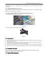
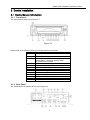
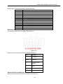
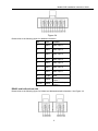
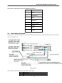
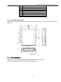
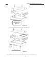
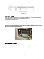
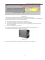
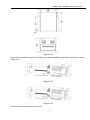
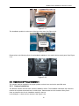
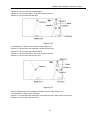
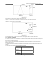
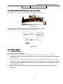
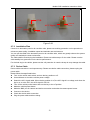
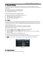
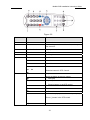
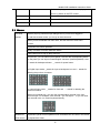
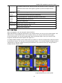
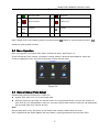
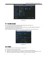
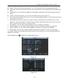
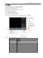
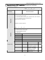
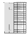
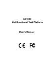
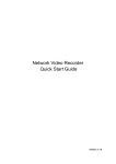
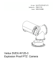
Mobile DVR Installation Instruction Guide 2010-01 Mobile DVR Installation Instruction Guide Table of Contents --------------------------------------------------------------------------1 PREPARATION ............................................................................................................... 5 1.1 General Installation Process ................................................................................................................................. 5 1.2 Installation Plan....................................................................................................................................................... 5 1.3 Installation Tools..................................................................................................................................................... 5 1.4 Installation Material ................................................................................................................................................ 5 1.4.1 Cable.................................................................................................................................................................... 5 1.4.2 Screw................................................................................................................................................................... 5 1.4.3 BS Thread Rod and Screw Cap ...................................................................................................................... 6 1.4.4 Protection Coil, Electrical Conduit and Protection Groove .......................................................................... 6 1.5 Preparation .............................................................................................................................................................. 6 1.6 Installation Principle ............................................................................................................................................... 6 1.7 Mobile DVR Installation ......................................................................................................................................... 6 1.7.1 2 Camera and Pickup Installation ....................................................................................................................... 7 DEVICE INSTALLATION ................................................................................................. 9 2.1 Device General Introduction ................................................................................................................................. 9 2.1.1 Front Panel ......................................................................................................................................................... 9 2.1.2 Rear Panel .......................................................................................................................................................... 9 2.1.3 Rear Cable Connection................................................................................................................................... 12 2.1.4 Installation Dimension ..................................................................................................................................... 13 2.2 HDD Installation .................................................................................................................................................... 13 2 Mobile DVR Installation Instruction Guide 2.3 Power Supply ........................................................................................................................................................ 15 2.4 Installation Position .............................................................................................................................................. 15 2.5 Camera and Pickup Installation.......................................................................................................................... 18 2.5.1 Camera Installation.......................................................................................................................................... 18 2.5.2 Pickup Installation............................................................................................................................................ 20 2.6 Mobile DVR PTZ Installation and Connection.................................................................................................. 21 2.7 Cable Layout ......................................................................................................................................................... 21 2.7.1 Installation Step................................................................................................................................................ 21 2.7.2 Installation Plan................................................................................................................................................ 22 2.7.3 Device Cable .................................................................................................................................................... 22 3 SETUP AND DEBUG..................................................................................................... 23 3.1 Log in...................................................................................................................................................................... 23 3.2 Remote Control..................................................................................................................................................... 23 3.3 Mouse..................................................................................................................................................................... 25 3.4 Live View................................................................................................................................................................ 26 3.5 Menu Operation .................................................................................................................................................... 27 3.6 General Setup (Plate Setup)............................................................................................................................... 27 3.7 Auto Maintenance................................................................................................................................................. 28 3.8 Encode ................................................................................................................................................................... 28 3.9 Search .................................................................................................................................................................... 30 3 Mobile DVR Installation Instruction Guide 3.9.1 3.10 4 Basic Operation................................................................................................................................................ 31 FAQ ........................................................................................................................................................................ 31 APPENDIX MOBILE DVR INSTALLATION ACCEPTANCE CERTIFICATE ................. 32 4 Mobile DVR Installation Instruction Guide 1 Preparation 1.1 General Installation Process Before installation, you need to know the installation includes the following steps: z You need to select the installation plan and installation technique according to your vehicle type. z You need to properly arrange the schedule for the vehicle to be installed. z Write down the vehicle plate number and its corresponding device number. z Select the installation position and complete the preparation works (dig holes, dismantle and etc.). z Lay down the cable. z DVR cable connection z DVR installation z Whole system debug and test. 1.2 Installation Plan The installation engineer and the people from vehicle technical department shall work together to draw out the installation plan and techniques. The both sides shall select the instillation vehicle together and the on-site engineer is responsible to get the device and accessory, check the quality and upgrade the mobile DVR software. During the installation process, the installation group is responsible to record the device corresponding code, technique check, cable connection and system debug. 1.3 Installation Tools The mobile DVR installation tool list is shown as below: z Phillips screwdriver z Bent strippers z Wire strippers z Needle nose pliers z Adjustable wrenches z Electronic runner (Dry cell runner is preferred.) z Multimeter z LCD for debug z A 2-meter steel cable (diameter 1.5mm.) to cable layout z 3.2mm and 4.5mm aiguille 1.4 Installation Material 1.4.1 Cable Cable is used to connect the power and the vehicle signal. For cable connected to the power, please use 1.0 square meter or higher 3-pin cable. For cable connect the vehicle signal, please use 0.25 square meter or higher 2-pin or 3-pin cable (including shielded layer). 1.4.2 Screw 5 Mobile DVR Installation Instruction Guide Screw is used to fix the camera or pick-up. Usually we use M5×12/ M5×14 self tapping screw to fix the camera and M3×8/ M3×12 self tapping screw to fix the pickup. You can select according to you actual environment. 1.4.3 BS Thread Rod and Screw Cap They are used to fix the device. Usually, we do not need these two accessories. If the installation position is difficult to choose, maybe you need them. 1.4.4 Protection Coil, Electrical Conduit and Protection Groove The trunking protection is shown as in Figure 1-1. Figure 1-1 The tube protection is shown as below. See Figure 1-2. Figure 1-2 1.5 Preparation z z z z Before installation please arrange the installation device and accessories. At the same time, record the device test and code. The installation group includes: one carriage worker, one electrician, one locksmith, one technical instructor and one technical engineer from your local retailer. The construction side shall provide the necessary installation condition such as the external power. If necessary, you can complete necessary preparation work, such as put the cable into the bellows). 1.6 Installation Principle Mobile monitor system installation includes: mobile DVR installation, camera installation, pickup installation, and cable layout and cable connection. 1.7 Mobile DVR Installation 6 Mobile DVR Installation Instruction Guide Mobile DVR installation shall following the listed principles: z Please fix the mobile DVR firmly. z The mobile DVR shall be away from the great vibration. You can install it at the rear of the driver seat or the front part of the vehicle. Please note the installation location shall not disturb the driver operation. z Please guarantee the sound ventilation and keep general distance from other devices. Do not install in the locked box such as the vehicle tool box. z The external cable shall have sound distance and protection to guarantee cable electronic safety. z Please make sure the mobile DVR is away from the heating objects. z Please check the installation is even. Any unstable installation may result in device damage. z When installing, please reserve considerable space for the HDD box to draw out. 1.7.1 Camera and Pickup Installation The camera and pickup installation position is depending on the monitor area your client focus. 1.7.1.1 Camera Installation Camera installation shall following the listed principles: z The installation position shall allow the client to view the specified zone. z Camera shall be easy to install and fix. z Camera cable layout is convenient. z There shall be no object to obstruct the camera. z Please take the light direction factor into consideration. 1.7.1.2 Cable Layout The cable layout is very important for mobile monitor system. The standard cable layout can guarantee system stability and reliability. Please note: z All cable shall be in the protection cable. The cable installation shall go along with the original cable and binding with the previous one. Please make sure the cable layout is neat and hidden in case the driver or passenger may break it. z Mobile DVR power cable: The mobile DVR shall connect to the storage battery of the vehicle and there shall be no control button. The cable is 3-pin power cable and its diameter shall be over than 1.0 square millimeters. (The cable connection shall be interlaid in case there is short circuit.). The cable length is depending on client requirement. Please note the battery position end and negative end shall be uniform. ACC signal cable shall connect to the vehicle key live cable. The video cable and audio cable shall adopt 4-pin flame retardation insulation protection cable and its diameter shall be over 0.5 square millimeters. z GPS antenna: For the mobile DVR to get the signal from GPS satellite, please install the GPS signal receive antenna at the proper front position of the vehicle. Then dig a hole to connect the transmission cable to the vehicle. Please use the glass cement or other way to seal the cable so that there is sound airproof of the vehicle. Please note, you should handle carefully, otherwise it may result in antenna damage. z During the cable layout, please make sure all cable are safe and will not be damaged. All connections and welding are safe and secure. The installation cable in the vehicle shall be properly tied and the two ends shall be neat and plain. The installation cable outside of the vehicle shall be fixed by the glass cement. The entire cable layout in the vehicle shall avoid the friction and the entire layout shall adopt the proper fasten way. z The cable strap shall be tighten and even. When use protection cable, please make sure there is no displacement and the cable can bend easily. 7 Mobile DVR Installation Instruction Guide z z All cable can work properly. There is no short circuit or wrong connection. Cable shall not open to the air directly. Please fasten the cable each 50cm when system adopts invisible cable layout. Please use rubber insulating blanket when the cable strap goes through the metal or side panel. All the cable layout and device installation here shall conform to your local electronic safety code. 1.7.1.3 Cable Connection Please connect the cable according to the signal symbol and the cable color. Note: before connection, please make sure all the cable is OK and the signal is valid. After connection, please weld the connection point and use the heat-shrinkable tube to guarantee the intensity. Important z All working engineers shall prepare the necessary installation tool. z All the connection shall be done by the professional engineer. z Please make sure the mobile DVR and vehicle are sound earthed, otherwise it may result in property damage or property loss! 8 Mobile DVR Installation Instruction Guide 2 Device Installation 2.1 Device General Introduction 2.1.1 Front Panel The front panel is shown as in Figure 2-1. Figure 2-1 Please refer to the following sheet for front panel button information. SN Function USB2.0 port 1 2 3 4 5 6 7 8 9 10 11 12 13 Power indication light. Channel record status indication light. It is on in normal status. It becomes flashing when abnormal event occurred. Lock/unlock indication light Backup indication light SD card indication light HDD indication light GPS indication light LAN indication light 3G indication light WIFI indication light On/Off button IR remote control receive window 2.1.2 Rear Panel The mobile DVR rear panel is shown as in Figure 2-2. 9 Mobile DVR Installation Instruction Guide Figure 2-2 Please refer to the following sheet for detail information. SN Function Audio/video input and camera power output port. 1 2 3/4 5 6 7 8 9 10/11 12 13 14 15 16 Audio/video output RS232 5V output and camera 12V input Device power input SIM card socket WIFI antenna port 3G antenna port Bidirectional talk port, 485 port. Alarm input /output port. Extension port GPS antenna port VGA port RJ45 network port Extension port The extension port is shown as below. See Figure 2-3. Figure 2-3 Please refer to the following sheet for detailed information. SN Function 1 5V output 2/46/8 USB port 3 Remote control receiver 5 GND 7 Video output (+) 9/10 Lamp Alarm input and output port Alarm input and output port is shown as below. See Figure 2-4. 10 Mobile DVR Installation Instruction Guide Figure 2-4 Please refer to the following sheet for detailed information. SN Color Function 1 White Alarm input 1 2 White Alarm input 2 3 White Alarm input 3 4 White Alarm input 4 5 White Alarm input 5 6 White Alarm input 6 7 White Alarm input 7 8 Purple GND 9/10 Yellow 11/112 Yellow Alarm normal open output 1 Alarm normal open output 2 RS485 and bidirectional talk Please refer to the following figure for RS485 and bidirectional talk information. See Figure 2-5. 11 Mobile DVR Installation Instruction Guide Figure 2-5 Please refer to the following sheet for detailed information. SN Function 1 GND 2 Micro phone 3 GND 4 Earphone 5 Volume control 6 A cable 7 GND 8 B cable 2.1.3 Rear Cable Connection Please refer to the following figure to connect audio input/output cable, video input/output cable and 16-pin cable. See Figure 2-6. Figure 2-6 Please refer to the following sheet for detail information. 1 Video input 2 Audio input 3 Video CVBS output 12 4 5 6 7 8 9 10 11 12 Mobile DVR Installation Instruction Guide Audio output Network port USB port HDMI port RS232 port Video VGA output Alarm input/alarm output/RS485 port Power input port Power button 2.1.4 Installation Dimension Please refer to the following figure for installation dimension information. Please note the unit is mm. See Figure 2-7. Figure 2-7 2.2 HDD Installation Dismantle HDD box. Please refer to the following figures for detail information. The first step, please dismantle the HDD box. See Figure 2-8. 13 Mobile DVR Installation Instruction Guide HDD box fix screw HDD bracket fix screw HDD fix screw Figure 2-8 The second step, please install the HDD. See Figure 2-9. HDD HDD box fix screw HDD bracket fix screw HDD fix screw Figure 2-9 After completing HDD, insert it into device HDD slot and then lock. See Figure 2-10. 14 Mobile DVR Installation Instruction Guide You can paste a label on the HDD box to identify them. Figure 2-10 2.3 Power Supply Usually, the mobile DVR shall get power from the vehicle distribution box. The cable shall go through the fuse of the vehicle. You can refer to the following figure. See Figure 2-11. Recommended power supply mode: z Usually there is radio in the vehicle. The radio power supply is the same with our mobile DVR. z You can get power from the keyhole. There is ACC and common power supply of the vehicle z For common power, you can get from the vehicle general power button. Please remember adding the necessary fuse. Please note, the vehicle supply power shall be larger than the device rated power and can support the extra large current when system boots up. Figure 2-11 2.4 Installation Position The DVR should be installed in a cool, dry place away from direct sunlight, inflammable, explosive substances and etc. At the same time, the installation position can guarantee convenient and reasonable cable layout. Please note, you need to reserve a proper distance to draw out the HDD box. 15 Mobile DVR Installation Instruction Guide HDD box Figure 2-12 Do remember using vibration isolation rubber gasket (provided) below the device. If the mobile DVR is installed in the bus, usually there shall be a iron box to guarantee system stability and make product duration longer. It has the following advantages: z The installation position is easy to choose if you add an iron box. z The iron box can guarantee sound dustproof and water proof capability. z The device port and cable can be put in the box, which can guarantee device safety and enhance convenient management. z The iron box can guarantee neat vehicle. Here is some general introduction of the Dahua mobile monitor system professional chassis. The multiple-layer chassis interface is shown as in Figure 2-13. Figure 2-13 Please refer to the following figure to multiple-layer chassis dimension. See Figure 2-14. 16 Mobile DVR Installation Instruction Guide Figure 2-14 Please refer to the following figure for multiple-layer chassis installation information. See Figure 2-15 and Figure 2-16. Figure 2-15 Figure 2-16 Here are some installation modes in the bus. 17 Mobile DVR Installation Instruction Guide The installation position is below the passenger seat. See Figure 2-17. Installation Position Figure 2-17 The installation position is at the rear of the bus driver seat. See Figure 2-18. Installation Position Figure 2-18 Please refer to the following figure for embedded installation in the small vehicle control panel. See Figure 2-19. Figure 2-19 2.5 Camera and Pickup Installation The camera shall be installed in the proper position so that it can monitor the specified area. 2.5.1 Camera Installation The different vehicle cameras have various installation modes. The installation shall allow the camera to monitor the required zone and there is no blind spot. Please make sure the camera is firmly fixed. Here we introduce the four-ch installation modes in the bus. In the blueprint 1, there are four cameras. See Figure 2-20. 18 Mobile DVR Installation Instruction Guide Camera 1: It is to monitor the road status of the bus front-end. Camera 2: It is to monitor bus internal status. Camera 3: It is to monitor driver, front door and bus coin box. Camera 4: It is to monitor the rear door. Figure 2-20 In the blueprint 2, there are four cameras. See Figure 2-21. Camera 1: It is to monitor the road status of the bus front-end. Camera 2: It is to monitor bus internal status. Camera 3: It is to monitor driver, front door and bus coin box. Camera 4: It is to monitor the bus rear end. Figure 2-21 Here we introduce the 2-ch installation modes in the bus. See Figure 2-22. In the blueprint 1, there are two cameras. Camera 1: It is to monitor the road status of the bus front-end., driver and the front door. Camera 2: It is to monitor bus rear door. 19 Mobile DVR Installation Instruction Guide Figure 2-22 In the blueprint 2, there are two cameras. See Figure 2-23. Camera 1: It is to monitor the road status of the bus front-end., driver and the front door. Camera 2: It is to monitor bus internal status. Figure 2-23 For long-distance bus, you can install a camera in the luggage cabin to monitor cabin status. 2.5.2 Pickup Installation The pickup we provide here max distance is 2 meters and the speaker needs to speak direct to the phone. Please follow the steps listed below. First, you need to check the speaker standing position and the speak direction. Usually the pickup is installed near the driver. The distance between the pickup and the speaker shall be within 2m and the angle shall be less than 75 degrees. You can refer to the following sheet for detailed information. Angle Distance 0 degree~3 0 ≤1.5 meters degrees 30 degrees ~ ≤1.2 meters 60 degrees 60 degrees ~ ≤0.75 meters 20 Mobile DVR Installation Instruction Guide 75 degrees 2.6 Mobile DVR PTZ Installation and Connection Please refer to the following figure for detailed information. See Figure 2-24. Figure 2-24 Note: Before PTZ installation, please check the position installation intensity. Mobile DVR PTZ connection layout is shown as in Figure 2-25. Figure 2-25 2.7 Cable Layout 2.7.1 Installation Step Please follow the steps listed below. z Confirm the device installation position. Please take the waterproof and vibration factor into consideration. Please note the position shall be easy to lay out cable and the cable shall not obstacle the driver’s view. z Please check if it is suitable to lay the hidden cable once the vehicle decoration panel is removable. The cable is usually under the decoration panel or the air condition tube. You still need to fix the cable if the cable can not be hidden, otherwise the cable may adversely affect the DVR operation or disturb the driver normal operation. z Joint: the device power input joint is DJ7031-6.3-11 and power input joint is DJ7031-6.3-21. See Figure 2-26 21 Mobile DVR Installation Instruction Guide GND GND ACC Signal Common Power Common Power ACC Signal Figure 2-26 2.7.2 Installation Plan If there is no decoration panel or air condition tube, please use trunking protection or tube protection to enhance system quality, installation speed and maintain neat environment. You can put the cable in the decoration panel or air condition tube, which can greatly enhance the system quality and maintain the neat environment. The cable shall be fixed during the installation. Please use cable strap to fix the cable. Please note the cable stability has great effect on the device performance. For the hole dug in the vehicle, please use the coil protection in case the sharp rim may damage the cable. 2.7.3 Device Cable Device cable connection is an important step. Please note before cable connection, please unplug the power cable. Please follow the steps listed below: z Turn on the vehicle main switch and turn the key position to off. z Use multimeter to check the vehicle power voltage. z Search the ACC signal cable. When the key position is off, the ACC signal is o voltage, and when the key is on or to the ACC, the ACC signal is 24v/12v. z Turn off the vehicle power button and turn the key to the off position. z Make the vehicle power button. z Make the BNC port for camera and device connection and make the camera power button. z Connect to the device. z Check the device cable connection. z Plug the power cable and then debug. 22 Mobile DVR Installation Instruction Guide 3 Setup and Debug After installation, please following processes listed below to check the device installation and electric connection and then begin system debug. The whole system needs to pass the all test and debug before it begins trial run. Before connect to the power socket. Please check: z The DVR power is within the normal threshold. z The signal connection is OK. Then you can boot up the device and begin debug. z Check the power button, mobile DVR indication light is OK. z GPS status and WiFi status are both OK. z The indication light is proper after DVR boots up. z Debug after DVR boots up normally. 3.1 Log in Turn the key to ACC, you can see power indication light becomes on and DVR boots up (DVR boots up might take several seconds). System is in multiple-window preview mode after boots up and record setup is continuous record mode. You can see corresponding channel indication light becomes on and record indication light becomes on too. After the system boots up, default video display is in multiple-window mode. Click Enter or left click mouse, you can see the login interface. See Figure 3-1. System consists of four accounts: z z z Username: admin. Password: admin. (administrator, local and network) Username: 888888. Password: 888888. (administrator, local only) Username: 666666. Passwords: 666666(Lower authority user who can only monitor, playback, backup and etc.) z Username: default. Password: default(hidden user) For your system security, please modify you password after first login. You can use USB mouse, front panel, remote controller or keyboard to input. About input method: Click to switch between numeral, English character (small/capitalized) and denotation. Figure 3-1 3.2 Remote Control The remote control interface is shown as in Figure 3-2. 23 Mobile DVR Installation Instruction Guide Figure 3-2 Serial Number Name Function 1 View Switch window 2 ID Click it to input device serial number, so that you can control it. 3 Number 0 to 9 Input password, channel or switch channel. 4 Record 5 Aux Auxiliary button 6 Enter Confirm button Menu Menu button Esc Cancel button S Direction buttons W 7 X Record Direction buttons in PTZ. Control. Stop button Zoom out button in the PTZ control Slow play Playback/pause Zoom in button in the PTZ control Backward │_ Previous Forward Various slow play speed and normal speed play. Focus (-) button in the PTZ control. f│ Next 24 Mobile DVR Installation Instruction Guide Various fats play speeds and normal play speed. 8 F1 Focus (+) button in the PTZ control. Shortcut button to backup 9 F2 Reserved for future use. 10 F3 Reserved for future use. 3.3 Mouse Left click System pops up password input dialogue box if you have not logged in. mouse In real-time monitor mode, you can go to the main menu. When you have selected one menu item, left click mouse to view menu content. Implement the control operation. Modify checkbox or motion detection status. Click combo box to pop up drop down list In input box, you can select input methods. Left click the corresponding button on the panel you can input numeral/English character (small/capitalized). Here ← stands for backspace button. _ stands for space button. In English input mode: _stands for input a backspace icon and ← stands for deleting the previous character. In numeral input mode: _ stands for clear and ← stands for deleting the previous numeral. When input special sign, you can click corresponding numeral in the front panel to input. For example, click numeral 1 you can input“/” , or you can click the numeral in the on-screen keyboard directly. Double left Implement special control operation such as double click one item in the file list click mouse to playback the video. 25 Mobile DVR Installation Instruction Guide In multiple-window mode, double left click one channel to view in full-window. Double left click current video again to go back to previous multiple-window Right click mode. Exit main menu and go to the preview interface. mouse Exit current menu without saving the modification. Press In numeral input box: Increase or decrease numeral value. middle Switch the items in the check box. button Page up or page down Move mouse Select current control or move control Drag mouse Select motion detection zone Select privacy mask zone. 3.4 Live View After you logged in, you can see main menu interface. Right click mouse or click the ESE button in the remote control, you can go to live view window. Left click mouse or click ENTER button in the remote control, you can go to the main menu again. In live view window, you can see system date, time and channel name. Here you can also view longitude, latitude and vehicle speed. See Figure 3-3. In multiple-window display mode, double click one window or click the corresponding channel number in the remote control, you can go to full-screen display mode. In one-window display, double click the vide window or click the multiple-channel preview button in the remote control you can go back to multiple-window display mode. Longitude/latitude and vehicle speed 26 Mobile DVR Installation Instruction Guide Figure 3-3 1 Recording status 3 Video loss 2 Motion detection 4 Camera lock 5 LON 7 SOG longitude Latitude 6 LAN Vehicle speed Note: Please refer to the following sheet for channel status. stands for opening switch function, stands for closing switch function. 3.5 Menu Operation After you logged in, the system main menu is shown as below. See Figure 3-4. There are total six icons: search, information, setting, backup, advanced and shutdown. Move the cursor to highlight the icon, then left click mouse to enter the sub-menu. Figure 3-4 3.6 General Setup (Plate Setup) General setup interface is shown as in Figure 3-5. z System time: here is for you to set system time z DVR No: when you are using one remote control to control several DVRs, you can give a name to each DVR for your management. Here you can input vehicle plate number so that you can distinguish the recorded video from various devices. Note: Since system time is very important, do not modify time casually unless there is a must! After completed all the setups please click save button, system goes back to the previous menu. 27 Mobile DVR Installation Instruction Guide Figure 3-5 3.7 Auto Maintenance Here you can set auto-reboot time and auto-delete old files setup. See Figure 3-6. You can select proper setup from dropdown list. Acc delay value ranges from 0 to 255 (unit: minute.) Please note you need to disable auto shutdown system function if you want to enable acc delay. After completed all the setups please click save button, system goes back to the previous menu. Figure 3-6 3.8 Encode Encode setting includes the following items. See Figure 3-7. z Channel: Select the channel you want. z Compression: system supports H.264. Or you can select from the dropdown list. z Resolution: System supports various resolutions, you can select from the dropdown list. For this model, main stream we can support D1/CIF/QCIF while extra stream CIF/QCIF. 28 Mobile DVR Installation Instruction Guide Bit rate: system supports two types: CBR and VBR. In VBR mode, you can set video quality. Quality: There are six levels ranging from 1 to 6. The sixth level has the highest image quality. Frame rate: there are six levels: 1 f/s,2f/s,3f/s, 6f/s,12f/s,25f/s. (Some series DVRs only support PAL 25f/s ) z Video/audio: you can enable or disable the video/audio respectively for the main stream and extra stream. z Overlay: click overlay button, you can see an interface is shown in Figure 3-8. Cover area (Privacy mask): Here is for you to set window blanking section. You can drag you mouse to set proper section size. Preview/monitor: privacy mask has two types. Preview means the privacy mask zone can not be viewed by user when system is in preview status. Monitor means the privacy mask zone can not be view by the user when system is in monitor status. Time display: You can select system displays time or not when you playback. Channel display: You can select system displays channel number or not when you playback. Car No. display: You can select system displays car number or not when you playback. GPS display: You can select system displays latitude and longitude or not when you playback. You need to enable the corresponding function and then click set button to set the specified position to display the information. z z z Please highlight icon to select the corresponding function. Figure 3-7 Figure 3-8 29 Mobile DVR Installation Instruction Guide 3.9 Search There are two ways for you to go to search menu. z Click Pause/Play button in the remote control. z Click search in the main menu. Search interface is shown as below. See Figure 3-9. Usually there are three file types: z R: regular recording file. z A: external alarm recording file. z M: motion detection recording file There are several playback windows. This System supports 1-ch playback. Figure 3-9 Please refer to the following Serial Number 1 2 3 4 5 6 7 8 9 10 11 12 13 sheet for more information. Function Play Backward Stop Slow play Fast play Previous frame Next frame Volume Previous file Next channel Next file Previous channel Search 30 Mobile DVR Installation Instruction Guide 14 Backup 3.9.1 Basic Operation 3.9.1.1 Playback There are various search modes: video type, channel number or time. The system can max display 128 files in one screen. You can use up/down button to turn page. Select the file name and double click mouse (or click enter button), you can view file content. 3.9.1.2 Accurate playback Input time (h/m/s) in the time column and then click playback button, system can operate accurate playback. 3.9.1.3 Synchronized playback function when playback During playback process, click numeral key, system can switch to the corresponding channel video of the same time. 3.9.1.4 Digital zoom When the system is in full-screen playback mode, drag your mouse in the screen to select a section and then left click mouse to realize digital zoom. You can right click mouse to exit. 3.9.1.5 File backup System supports backup operation during search. You can draw a √ before file name (multiple choices). Then click backup button (Button 14 in Figure 3-9). Note: All the operations here (such as playback speed, channel, time and progress) have relationship with hardware version. Some series DVRs do not support some functions or playback speeds. If the search function is OK, then you can see the whole system is running properly. Please refer to the Mobile DVR User’s Manual for network setup and PTZ setup information. 3.10 FAQ Q: I can not boot up the mobile DVR. A: Please check power supply is proper or not. Then check the key power is open or not (ACC signal). The device can boot up after you enabled the power. Q: One channel video is missing in preview mode. A: Please check corresponding channel signal input is proper or not. Q: Device reboots frequently. A: Please check your have installed HDD or not. Q: Device does not delay but I have enabled key power (ACC) latch function. A: Please check power cable and ACC signal cable connection is OK or not. 31 Mobile DVR Installation Instruction Guide 4 Appendix Mobile DVR Installation Acceptance Certificate Here is a sheet for you reference Mobile DVR Installation Acceptance Certificate Date: ____Y____M_____D Client Name Manufacturer Name First, you can check the following items: z Device quantity and model. z Check the product warranty card, certificate card, user’s manual. z Device appearance and accessories bag. Initial Check Vehicle Supervisor Signature: Installation engineer signature: Date: ____Y____M_____D Then you can check the following items: Installation z Camera position and its angle. z Device installation position. z Cable layout. Device Installation Position Mobile DVR Camera Pickup Regulated Power Power supply Main Function Function Test Item Detail Monitor 4-ch real-time monitor. When select one channel, it can reach D1 resolution. Record search and playback. It can display record type, record time , channel title and etc. Provide different rights for different users. Search User Account 32 Accept HDD Info System Information BPS Log Version System Setup Mobile DVR Installation Instruction Guide HDD connection status, HDD total capacity, free capacity, record start/end time and etc. Use wave to display current bit stream and its HDD use within per hour. Display system log and can specify the log type. Hardware specification, software version and release date. General System time, record storage mode, DVR number and etc. Encode Audio/video encode mode, frame rate, quality and etc. Record Schedule record, external alarm record and etc. COM Set COM, baud rate and etc. Network Set network address, port and etc. Alarm Set external alarm output and record respond parameter setup. Motion Detection PTZ Set video loss parameter. Set PTZ communication protocol, baud rate and etc. Default Select some item(s) or select all items to restore factory default setup. Please note user account does not support this function. Advanced HDD management HDD management, clear data and etc. Abnormity Alarm setup for no HDD, HDD error and etc. 33 Mobile DVR Installation Instruction Guide Auto Set the auto maintenance Maintenance item. TV Adjust Adjust the playback output video zone. Backup Detect Check backup device, list the backup devices available, display name Backup operation and capacity. Backup the file(s) to the device. Vehicle Supervisor Signature: Installation Engineer: Date: ____Y____M_____D Accept Signature Client Authorized Representative Signature: Date:____Y____M_____D SN Plate Self- Number defined Device SN Version Number Note Number Note Slight difference may be found in the user interface. All the designs and software are subject to change without prior written notice. Please visit our website for more information. 34