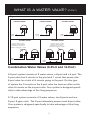
1
Cleaning System Manual
OWNER’S MANUAL
For PCC2000, PV3, Cyclean, Pool Valet,
New Pool Valet, Vantage, Vanquish,
StepClean, SwingSweep and EcoPool
004-027-8742-00
REV052313
US and Foreign patents and patents pending –
www.paramountpools.com/patents/
295 East Corporate Place • Suite 100 • Chandler, AZ 85225
Toll Free: 1.800.621.5886 • Phone: 480.893.7607 • Fax: 480.753.3397
[email protected] • www.1Paramount.com
1
TABLE OF CONTENTS
Congratulations!.............................................................................. 3
What You Need to Know............................................................... 3
What is a Water Valve?................................................................. 4-5
Unique Water Valve Features....................................................... 6
Water Valve Parts Breakdown...................................................... 7
Water Valve Instructions................................................................ 8-15
How to Open the Water Valve................................................. 8
Module Installation (6-port)....................................................... 9-10
Module Installation (2-port, 3-port, 4-port)............................ 11-12
Alignment Guide ........................................................................ 13
How to Close the Water Valve................................................. 14
Run/Pause Switch...................................................................... 15
Nozzles (Cleaning Heads)............................................................. 16
Nozzle Removal/Installation.......................................................... 17-20
Optional Paramount Debris Canister ........................................ 21
Relationship with Pool Equipment............................................... 22-25
Cleaning Systems Powered by the Filter Pump................... 22
Cleaning Systems Powered by a Booster Pump................ 23
Filters.............................................................................................. 23-24
Valves for a single Pump System............................................ 24
Chlorinators, Tablet or Salt Systems, Ozone, Solar............. 24-25
Operating Instructions................................................................... 26
Troubleshooting Guide for Paramount In-Floor Systems....... 27-29
Warranty Certificate........................................................................ 30
Copyright © 2013 Paramount Pool & Spa Systems. All Rights Reserved.
Contact Paramount Pool & Spa Systems at 1.800.621.5886
2
CONGRATULATIONS
Congratulations on your new pool and thank you for choosing one of
Paramount’s cleaning or circulation systems. This manual will address
all of Paramount’s systems, the PCC2000, PV3, Cyclean, Pool Valet,
New Pool Valet, Vantage, Vanquish, Step Clean, Swing Sweep, and Eco
Pool. Your system may also include a Paramount debris canister and
one or more of Paramount’s Drains (MDX-R3, MDX2, MDX, Buzztop
Channel Drain and/or SDX).
WHAT YOU NEED TO KNOW
Your system’s performance will be maximized by adhering to the following operating instructions, and can be affected by seasonal weather
conditions that may require extended periods of operation. The cleaning performance directly relates to the type and design of your specific
Paramount system.
It is recommended you call your pool builder or a professional service
company if your pool requires attention.
3
WHAT IS A WATER VALVE?
The Paramount water valve is fully
automatic and operates whenever the
pump it’s connected to is running.
Your Paramount Water Valve may be
connected to your filter pump or a
stand-alone “booster” pump.
The water valve automatically distributes water to different areas of your
pool, which can include the floor, steps, benches, spa and
water features. It cycles much like an automatic sprinkler system in your yard switching from one circuit to another (Figure
1 shows the combination of water valves). Every water valve
has a center port. This is where the water enters the valve.
You will have a 2-port, 3-port, 6-port, 9-port or 12-port system
depending on the design of your pool. The port count of the
water valve indicates the number of circuits that send water
back to your pool or to another water valve. Cleaning nozzles
or returns are placed at the end of the circuits.
4
WHAT IS A WATER VALVE?
(CONT.)
Figure 1
2 PORT VALVE
FROM
PUMP
3 PORT VALVE
FROM
PUMP
6 PORT VALVE
FROM
PUMP
9 PORT VALVE
12 PORT VALVE
12 PORT VALVE - 2 PORT
SPECIAL VALVE PORTED
INTERNALLY TO FEED 3
CIRCUTS THROUGH 1 PORT
9 PORT VALVE - 4 PORT
SPECIAL VALVE PORTED
INTERNALLY TO FEED 3
CIRCUTS THROUGH 1 PORT
FROM
PUMP
FROM
PUMP
Combination Water Valves (9-Port and 12-Port)
A 9-port system consists of 2 water valves, a 6-port and a 4-port. The
4-port valve has 3 circuits to the pool and 1 circuit that powers the
6 port valve for a total of 9 circuits going to the pool. On this type
of system the 3 circuits on the 4-port valve fire twice as often as the
other 6 circuits on the six port valve. Your system is designed specifically to take advantage of this firing sequence.
A 12-port system consists of 3 water valves, two 6-ports and one
2-port, 5 gear valve. The 2-port alternately powers each 6-port valve.
Your system is designed specifically to take advantage of this firing
sequence.
5
UNIQUE WATER VALVE FEATURES
The run/pause switch on the top of the valve allows you to pause the
system to isolate a circuit in an out of the way area of the pool.
The one-piece replacement module design allows for easy installation.
The gauge on your water valve is important and tells you how the
system is operating. Gauges should be replaced when they become
unreadable or inaccurate. Never use Teflon tape on a replacement
gauge, use a thread sealant that is approved for plastic such as
Teflon paste. Hand tighten gauge as over tightening can crack the
water valve lid.
6
WATER VALVE BREAKDOWN
Figure 2
Top Dome Complete
Includes Top, Gauge & Pause Assembly:
005-302-4300-03
Modules:
004-302-4400-00
004-302-4402-00
004-302-4404-00
004-302-4406-00
004-302-4408-00
2
2
3
4
6
Port 4 Gear
Port 5 Gear
Port
Port
Port
Band Clamp Complete
Includes Knob & Nut:
005-302-3570-00
Base O-Ring:
005-302-0100-00
Valve Base (US)*:
005-302-4000-03
005-302-4010-03
005-302-4016-03
005-302-4030-03
2
3
4
6
Port
Port
Port
Port
Base
Base
Base
Base
1”1/2
1”1/2
1”1/2
1”1/2
Valve Base (US)*:
005-302-4002-03
005-302-4012-03
005-302-4018-03
005-302-4032-03
2
3
4
6
Port
Port
Port
Port
Base
Base
Base
Base
2”
2”
2”
2”
Black
Black
Black
Black
Valve Base (Metric):
005-302-4006-03
005-302-4009-03
005-302-4020-03
005-302-4038-03
2
3
4
6
Port
Port
Port
Port
Base
Base
Base
Base
63
63
63
63
mm
mm
mm
mm
Black
Black
Black
Black
Black
Black
Black
Black
*US 2” is equivelant to Australian 50 mm.
Pressure Gauge:
005-302-3590-00
Band Clamp Nut:
005-302-0640-00
Pause Assembly (Includes
Screw Knob, O-Ring & Pawl)
005-302-3502-00
Band Clamp Knob:
005-302-3600-00
NOTE: Winterizing plug is for 2 inch and
63 mm only.
Winterizing Plug:
004-302-1670-00 (Single)
004-302-1672-00 (6 Pieces)
For 1 ½ inch valve base use a standard #8
winterizing plug.
7
WATER VALVE INSTRUCTIONS
How to open the water valve
1. TURN OFF ALL EQUIPMENT INCLUDING PUMPS.
WARNING! FAILURE TO DO SO CAN RESULT IN INJURY OR
DEATH.
2. Remove the band clamp by turning the clamp knob or 7/16 inch
nut counter-clockwise until it comes off the bolt. Then carefully
pull the clamp away from the valve.
3. Lift the top off the base being careful to not lose or stretch the
o-ring.
4. Remove the module by lifting up and out of the base.
Note: the module is designed to seal inside the base so it may
require a side to side or rocking motion while lifting out. An easy
solution is to turn the pump on and off quickly. CAUTION! DO
NOT APPROACH THE WATER VALVE WHILE THE THE LID IS
REMOVED AND THE PUMP IS ON. FAILURE TO DO SO CAN
RESULT IN INJURY OR DEATH.
5. Do not pull the module by the gear mechanism. This can result in
damage to the module.
8
WATER VALVE INSTRUCTIONS
(CONT.)
Module Installation (6-port)
1. Check the o-ring and groove for debris, and clean if necessary
(this is a quad ring and is almost square, the height is slightly bigger than the width).
2. Replace the o-ring (Part # 005-302-0100-00) if it is stretched or
damaged. The o-ring does not require any lubrication. Lubricating
o-ring can attract dirt and debris that could prevent it from sealing. Never use petroleum jelly on plastic or rubber parts, as this
will damage them.
3. Set the module in the base and turn until the alignment pins on
the bottom of the module drop into the alignment holes in the
base (Figure 3).
4. The module should fit in the base without forcing it. If it does not
seat easily then check the following.
•
(Figure 3) shows the piston portion of the current module
design (released 06-2011). These pistons are set at the
factory. Do not touch, pull or turn these pistons. Any handling
will negatively affect the performance and fit of this product.
•
If the flow optimizer (Figure 4) prevents the module from
seating properly in the base you may have to remove it. To
remove optimizer press in on the 3 clips and pull to seperate.
9
WATER VALVE INSTRUCTIONS
Figure 3
MODULE
(BOTTOM VIEW)
ALIGNMENT PINS
SIDE VIEW
PISTONS
BASE
(TOP VIEW)
ALIGNMENT HOLES
Figure 4
(RELEASED 06-2011)
10
(CONT.)
WATER VALVE INSTRUCTIONS
(CONT.)
Module Installation & Alignment Guide (2-port,
3-port, 4-port)
1. Check the o-ring and groove for debris and clean if necessary
(this is a quad ring and is almost square, the height is slightly
bigger than the width).
2. Replace the o-ring (Part # 005-302-0100-00) if it is stretched or
damaged. The o-ring does not require any lubrication. Lubricating
o-ring can attract dirt and debris that could prevent it from sealing.
Never use petroleum jelly on plastic or rubber parts, as this will
damage them.
3. The module should fit in the base without forcing it. If it doesn’t
seat easily then check the following.
•
2-port module alignment – on the 2-port module the ports
on top of the module that are attached together by tubes
must be centered over the open ports in the valve base
(Figure 5).
•
3-port module alignment – on the 3-port module the ports
on top of the module that are attached together by tubes
must be aligned over an open port and a closed port section (Figure 5).
•
4-port module alignment – on the 4-port module the ports
on top of the module that are attached together by a tube
11
WATER VALVE INSTRUCTIONS
(CONT.)
must be aligned over the half of the base that has only one
port (Figure 5).
4. Set the module in the base and rotate slightly back and forth until
the alignment pins on the bottom of the module drop into the
alignment holes in the base (Figure 3).
5. The module should fit in the base without forcing it. If it does not
seat easily then check the following.
•
(Figure 3) shows the piston portion of the current module
design (released 06-2011). These pistons are set at the
factory. Do not touch, pull or turn these pistons. Any handling will negatively affect the performance and fit of this
product.
•
If the flow optimizer (Figure 4) prevents the module from
seating properly in the base you may have to remove it.
To remove optimizer press in on the 3 clips and pull to
seperate.
12
WATER VALVE INSTRUCTIONS
(CONT.)
Alignment Guide
Figure 5
2 PORT / 4 GEAR // MODULE, BASE
3 PORT
Used for basin & spa applications, Eco Systems & Swing Sweep
Used for Eco Systems & Swing Sweep
Module Part# 004-302-4400-00
Base Part# 005-302-4002-03 (2”)
005-302-4006-03 (63mm)
// MODULE, BASE
Module Part# 004-302-4404-00
Base Part# 005-302-4012-03 (2”)
005-302-4009-03 (63mm)
2 PORT / 5 GEAR // MODULE, BASE
4 PORT // MODULE, BASE
Used on 12 port systems to feed the two 6 port valves
Found on 9 port systems - feeds 6 port valve
Module Part# 004-302-4402-00
Base Part# 005-302-4002-03 (2”)
005-302-4006-03 (63mm)
Module Part# 004-302-4406-00
Base Part# 005-302-4018-03 (2”)
005-302-4020-03 (63mm)
6 PORT // MODULE, BASE
Module Part# 004-302-4408-00
Base Part# 005-302-4032-03 (2")
005-302-4030-03 (1½")
005-302-4038-03 (63mm)
*US notation of 2” is equivalent to Australian 50 mm.
13
WATER VALVE INSTRUCTIONS
(CONT.)
How to close the water valve
1. Check the o-ring and groove for debris, and clean if necessary
(this is a quad ring and is almost square, the height is slightly bigger than the width)
2. Replace the o-ring if it is stretched or damaged. The o-ring does
not require any lubrication. Lubricating The o-ring can attract dirt
and debris that could prevent it from sealing. Never use petroleum
3.
4.
5.
6.
7.
jelly on plastic or rubber parts, as this will damage them.
Place the run/pause switch in the run position then install the
valve top onto the base. The lid may be rotated in any direction
for easy viewing of pressure gauge.
Place the band clamp around the valve shells and put the clamp
knob or 7/16 nut on the threaded bolt.
Tighten the knob/nut securely. Note: Gently tap the band clamp
starting opposite the knob/nut going around both sides. While
periodically tightening the knob/nut. Be careful not to over tighten
the knob/nut.
Turn on the pump and inspect the water valve for leaks.
CAUTION! NEVER stand over any pool equipment when starting
the pump after working on it.
If you find leaks, turn off the pump and tighten the band clamp
more. If it continues to leak, repeat the above steps. If this doesn’t
work, replace the o-ring.
14
WATER VALVE INSTRUCTIONS
(CONT.)
The Run/Pause control switch
The run/pause control switch
is used to stop the cleaning
system circuits from cycling.
When switched to the pause
position, it will stop on the
circuit that is up at that time.
The run/pause control switch
should only be used when you
desire the nozzles not in the
up position to remain down or
while servicing the system.
Figure 6
Note: The run/pause control switch can be used without turning
off the pump, but can cause damage to the water valve or module
diaphragms if overused. If you frequently use the run/pause control
switch you should turn off the pump first. Always turn the run/pause
control switch to the run position when removing and replacing the
water valve lid.
15
NOZZLES (CLEANING HEADS)
All Paramount nozzles are sized and placed specifically for your
pool by Paramount. These nozzles have different sized openings and if removed, should be returned to the same location.
NOTE: Switching nozzle(s) location will result in poor cleaning
and could severely damage your pool equipment.
All of your system nozzles must extend and retract completely with
each cycle of the water valve. Depending on the cleaning system, it
will take 12 to 18 cycles for a nozzle to rotate 360 degrees. There
are two exceptions to this.
1. The PCC2000 and Vantage systems can have one to three
nozzles (called Fixed Nozzles) that do not rotate and remain active
while pool filter pump is on. These nozzles are located near the
main drain and need to be aimed at the main drain.
2. The optional Swing Jet nozzles are placed on the sidewall of
a pool, and rotate back and forth between three positions in a
90-degree arc. They must retract and extend fully to move to the
next position.
16
NOZZLE REMOVAL /INSTALLATION
Nozzles may need to be removed from time to time for purposes of
winterizing or to flush debris from the lines and/or nozzles. There are
3 methods of removing the 8 different types of nozzles.
Method 1:
For Vanquish, Vantage and PCC2000 floor nozzles see Figure 7.
Using the removal tool common to these nozzles, attach the tool to
the end of your pool pole placing it over the nozzle and making sure
the tool tabs insert into the nozzle slots. Turn the tool clockwise a ¼
turn to unlock the nozzle and then lift it from the body in the floor of
the pool. When replacing the nozzle, be sure the body is free from
all debris or the nozzle will not lock in place. Make sure the o-ring on
the bottom of the nozzle is in place. Lock the nozzle into the tool on
the end of your pool pole and replace the nozzle in the body and turn
counter clockwise to lock into the body.
NOTE: Sand and pebbles can get between the body and the nozzle
and make it very difficult to remove a nozzle. To make the nozzle removal easier, use a pressure nozzle on a garden hose (like you use to
clean the side walk) and blow the debris out between the nozzle and
body before using the tool to
Figure 7
remove the nozzle.
NOTE: The nozzle is specific
to the body it came out of.
Always put the nozzle back in
the same body it came out of.
Part Number: 004-552-5440-00
Part Number: Vantage 004-602-5440-00, Vanquish 004-577-5440-00, PCC
004-552-5440-00
17
NOZZLE REMOVAL /INSTALLATION (CONT.)
Method 2:
Some PCC2000 systems used the large floor nozzle in the steps.
See Method 1 for removal and installations instructions.
PV3, Cyclen and PCC2000 step nozzles see Figure 8. Using the
removal tool common to these nozzles, attach the tool to the end of
your pool pole placing it over the nozzle and making sure the tool
tabs insert into the nozzle slots. Turn the tool counter-clockwise a ¼
turn to unlock the nozzle and then lift it from the body in the floor of
the pool. Make sure the o-ring on the bottom of the nozzle is in place.
When replacing the nozzle, lock the nozzle into the tool on the end of
your pool pole and replace the nozzle in the body and turn clockwise
to lock into the body.
NOTE: Sand and pebbles can get between the body and the nozzle
and make it very difficult to remove a nozzle. To make the nozzle removal easier, use a pressure nozzle on a garden hose (like you use to
clean the side walk) and blow the debris out between the nozzle and
body before using the tool to remove the nozzle.
NOTE: The nozzle is specific to the body it came out of. Always put
the nozzle back in the same body it came out of.
Figure 8
Part Number: 004-627-5452-00
Part Number: Cyclean 004-652-5452-00, PCC 004-552-5452-00, PV3 004-627-5452-00
18
NOZZLE REMOVAL /INSTALLATION (CONT.)
Method 3:
Pool Valet (released in 1980) and Step Clean see Figure 9. Using
the removal tool common to these nozzles, place the ends of the
U-shaped tool in 2 of the slots and turn counter-clockwise. This is a
threaded retainer ring that will require 3 full turns to remove. If you experience difficulty unthreading the retainer ring tap on it gently. This
is best accomplished by tapping on the top of the tool. The amount
of force necessary can vary depending on how long the nozzle has
been installed. When replacing the threaded ring of the nozzle wrap it
twice with Teflon tape. This will make for easy removal in the future.
Turn it clockwise approximately 3 turns until it is snug in the body.
NOTE: Sand and pebbles can get between the body and the nozzle
and make it very difficult to remove a nozzle. To make the nozzle removal easier, use a pressure nozzle on a garden hose (like you use to
clean the side walk) and blow the debris out between the nozzle and
body before using the tool to remove the nozzle.
NOTE: The nozzle is specific to the body it came out of. Always put
the nozzle back in the same body it came out of.
Figure 9
Part Number: 004-502-5420-00
19
NOZZLE REMOVAL /INSTALLATION (CONT.)
Method 4:
New Pool Valet (October 2012) Using the removal tool common to
these nozzles, place the tool in the 4 slots and turn counter-clockwise.
This is a threaded retainer ring that will require 1 full turn to remove. If
you experience difficulty unthreading the retainer ring tap on it gently.
When replacing the nozzle, snap the center of the nozzle into the tool
on the end of your pool pole and replace the nozzle in the body, turning clockwise 1 full turn to lock into the body.
NOTE: Sand and pebbles can get between the body and the nozzle
and make it very difficult to remove a nozzle. To make the nozzle
removal easier, use a pressure nozzle on a garden hose (like you use
to clean the side walk) and blow the debris out between the nozzle
and body before using the tool to remove the nozzle.
NOTE: The nozzle is specific to the body it came out of. Always put
the nozzle back in the same body it came out of.
Figure 10
Part Number: 004-502-5410-00
20
OPTIONAL PARAMOUNT DEBRIS CANISTER
Your pool may be equipped with the Paramount optional debris
canister, which would be located in the deck next to your pool. The
debris canister is where the debris from your pool is gathered after it
passes through the drain. This debris needs to be emptied from the
debris canister’s catch basket/bag regularly. It is important to empty
the basket in the debris canister on a regular basis, just like your
skimmer and pump baskets, so your pool equipment will continue to
operate efficiently. This debris canister has a patented water sealed
easy to remove twist lock lid that needs no o-ring. The Paramount
debris canister’s water sealed lid has an equalizer running from the
debris canister to the pool to keep water on top of the lid. The equalizer line must be kept clear from obstructions.
Paramount offers a high capacity stainless steel replacement basket
for your debris canister (Part # 005-152-8031-00).
21
RELATIONSHIP WITH POOL EQUIPMENT
Cleaning Systems Powered by the Filter Pump
1. Pumps must be capable of maintaining 20 psi (138 kPa) on the
water valve(s) pressure gauge.
2. Your pump must be capable of maintaining 20 psi (138 kPa) at
the water valve regardless of the additional features on your pool
such as spas, solar heating systems, heat pumps, water features,
chlorinators, or any other device that is powered by your pump.
3. Adding items to your filter system after construction (solar, heat
pumps, water features, chlorinators, and any thing that takes
pressure away from the nozzles) will have a negative effect on
the cleaning system. Please contact your builder or Paramount
before adding these items.
4. Keeping filter clean is required to maintain the 20 psi (138 kPa) at
the water valve. A dirty filter will prevent your system from cleaning
the pool.
5. The in-floor system comes with a pressure gauge on the water
valve and although the system may operate at lower psi, the best
cleaning results require 20 to 24 psi (138-165 kPa) at the water
valve pressure gauge. You will see reduced performance if the
system is operated at less than ideal pressure.
6. The systems cleaning cycle is determined by many factors (landscape, temperature, weather and condition of pool equipment).
To determine your cleaning cycle, run the pool until it is clean. In
extreme conditions an extended cycle will be necessary.
7. It is important to keep the skimmer and pump basket(s) empty, so
22
RELATIONSHIP WITH POOL EQUIPMENT
(CONT.)
your pool equipment will power your in-floor system. Failure to do
so will negatively affect the performance of your system.
8. When cleaning your cartridge or D.E. Filter care must be taken
before removing the filter elements that the filter tank be drained
and rinsed out. This is required to prevent dirt and debris from
entering the return line and getting into your in-floor system or any
other down-line components.
Cleaning Systems Powered by a Booster Pump
1. Because booster pump systems are designed to pull from the
skimmer(s) and not use a filter, they are not affected by the typical reductions in performance that affect filter pump systems.
Booster pumps need to produce a minimum of 65 gpm (246 lpm)
at 60 ft. (179kpa of head).
2. It is important to keep the skimmer and pump basket(s) empty, so
your pool equipment will power your in-floor system. Failure to do
so will negatively affect the performance of your system.
Filters
1. A clean pool filter is necessary for optimum system performance.
Your pool filter needs cleaning when filters pressure increases
5 psi (34 kPa) above the pressure showing when your filter is
clean.
2. If the need arises to replace your filter and/or its backwash valve
it is important that they are properly sized.
23
RELATIONSHIP WITH POOL EQUIPMENT
(CONT.)
• Sand Filter minimum size 4.9 square feet/.46 square meters
• D.E. Filter minimum size 48 square feet/4.5 square meters
• Cartridge Filter minimum size 200 square feet/19 square
meters
• Backwash Valve minimum size 2 inch or 63 mm Europe
• Backwash Valve minimum size 2 inch or 50 mm Australia
NOTE: Larger filter sizes will reduce the amount of cleaning needed.
NOTE: Be sure your replacement filter is adequately sized for your
existing pump.
Valves for a Single Pump System
1. The skimmer suction should be restricted to make the main drain
pull more, because water takes the path of least resistance, and
in-floor systems do most of their cleaning from the main drain
2. Returns, spa over flows, and water features must be turned off or
restricted on single pump system so that the in-floor system will
have proper pressure. Minimum 20 psi (138 kPa) is needed to
run the system.
Chlorinators, Tablet or salt systems, Ozone units
and Solar Systems
1. Cells on salt chlorinators must be kept clean. Failure to do so will
reduce the performance of your in-floor cleaning system.
2. If you add a salt chlorinator after your pools construction it is
24
RELATIONSHIP WITH POOL EQUIPMENT
(CONT.)
recommended to put cells on a bypass loop.
3. Any device that uses a venturi injection system on the return side
of the filter is not recommended on single pump in-floor system.
4. Solar systems on a single pump require a specific plumbing
method, which includes a small booster pump for the solar
system (Figure 11).
Figure 11
VACUUM BREAKER
COLLECTOR
PANELS
IN-LINE
BOOSTER
PUMP
CHECK
VALVE
SOLAR SENSOR
RETURNS
FILTER
POOL PUMP
POOL SYSTEM
25
CLEANING
SYSTEM
OPERATING INSTRUCTIONS
1. On all Paramount in-floor cleaning and circulation systems it is
important to keep the skimmer, the pump and the debris canister
baskets clean. It is also important to clean your filter when the
pressure rises 5 psi (34 kPa) over the clean starting pressure.
2. The gauge on your water valve is important and tells you how
the system is operating. Gauges can deteriorate over time and
should be replaced when they become unreadable or inaccurate.
Never use Teflon tape on a replacement gauge, use a thread
sealant that is approved for plastic such as Teflon paste. Hand
tighten gauges as over tightening can crack the water valve lid.
3. If a nozzle is stuck open or up when the pump shuts off you may
clear it by pushing down on it a few times while pump is on to
clear the obstruction.
4. No cleaning system is 100%. Paramount’s in-floor guarantee
is the strongest in the industry but some attention to the pool is
required to keep your backyard oasis beautiful. You must keep
your chemicals at proper levels, and brush any small areas that
may have a build up of heavy sand or debris. Keep in mind that
when excessive debris gets into a pool, such as large amounts of
leaves in the fall or dirt during a dust storm, no cleaning system
can do the job without some help, so be sure your equipment is
maintained.
5. On PCC and Vantage systems that may have fixed nozzles they
may need to be adjusted to keep their flow of water aimed in
the direction of the debris drain. These nozzles can be turned
clockwise when in the up position by pushing down slightly and
rotating them towards the main drain.
For further instructions see troubleshooting guide (pg 27-29).
26
Troubleshooting Guide for
Paramount In-Floor Systems
Problem
Diagnosis
Solution
Cleaning
nozzles(s) are
staying up when
the pump is off
Cleaning nozzles could be
jammed with sand or debris
which could result from improper
cleaning of your pool filter. See
section Paramount’s systems
relationship to your pool’s
equipment.
Isolate the circuit of the jammed
or stuck cleaning nozzles using
the pause switch on your water
valve. With the system pump
running push the cleaning
nozzles down repeatedly with
your foot or pool pole.
Cleaning nozzles
on a circuit stay
up once the
water valve has
switched to the
next circuit but
retract when the
system is off.
A circuit in the water valve is
staying open due to a jammed
piston in the module. This
could be caused by debris
entering the water valve.
Remove the module from the
water valve (see module removal
procedure) clean it by holding it
in the pool sideways and move
it back and forth quickly until it
is clean. If there are any pistons
in the open position, push them
shut being sure not to rotate
them. Place the module back
in the water valve (see module
installation procedure) and turn
the system pump on to determine
if the cleaning nozzles are now
functioning properly. Depending
on the age of the module, if this
does not solve the problem it
may be time to purchase a new
module.
NOTE: PCC AND VANTAGE
BOOSTER PUMP SYSTEMS
MAY HAVE FIXED NOZZLES
ON THE FILTER PUMP
WHICH STAY UP WHILE THE
FILTER PUMP IS ON.
It is always best to call a trained professional to service your pool
Further information on your cleaning system can be found at: www.1paramount.com
27
Troubleshooting Guide for
Paramount In-Floor Systems
Problem
Diagnosis
Solution
System is not
cleaning as it
used to.
Check for minimum operating
pressure of 20 psi (138 kPa) on
the water valve.
Check the run time of your in
floor system. It may need to be
extended. Especially during increased demand due to weather
conditions or bather load. Refer
to the section titled Paramount’s
systems “relationship to your
pool’s equipment”. If after following these steps and the problem
still exists call a trained professional to service your pool.
System is not
cleaning as it
used to.
Pool drain is plugged.
With the filter pump and booster
pump (if applicable) both running
adjust your valves on the filter
pump to draw 100% from the
pool drain. If your filter pump becomes noisy (cavitates) your pool
drain may be obstructed. At this
point call a trained professional
to service your pool.
An area around
one nozzle that
is going up and
down is not being
cleaned.
Cleaning nozzle is partially or
completely blocked.
Refer to the Nozzle/Installation
and Removal section. Remove
the nozzle. With the nozzle removed turn on the system pump
to blow out the circuit. Check
the nozzle for debris stuck inside.
Replace the nozzle.
It is always best to call a trained professional to service your pool
Further information on your cleaning system can be found at: www.1paramount.com
28
Troubleshooting Guide for
Paramount In-Floor Systems
Problem
Diagnosis
Solution
The water valve
• Run/Pause switch is in the
• Turn the run/pause switch to
stays on one
pause position.
run.
circuit. One
• The module gear mechanism • Take the module out of the
circuit of nozzles
could be jammed.
water valve (refer to Water
running constantly • System could have incorValve Instructions) and conand not switching.
rectly sized nozzles
firm that the gear mechanisms
• System could have a plugged
turn freely. If it does not, recircuit
move all debris. If it still does
not work, replace the module.
• Check for pressure above
25 psi (172 kPa) at the water
valve. If the pressure does
not change or changes very
slowly (longer than 3 minutes) and if the nozzle(s) have
been removed they may have
been replaced in the wrong
locations. Nozzle(s) are size
and location specific to your
system.
• Remove nozzle(s) refer to
the Nozzle/Installation and
Removal section. Turn the
system pump on to blow out
the circuit. Replace Nozzle(s).
It is always best to call a trained professional to service your pool
Further information on your cleaning system can be found at: www.1paramount.com
29
Paramount Pool & Spa Systems (PP&SS)
295 E. Corporate Place, Suite 100
Chandler, AZ 85225
1.800.621.5886
www.1Paramount.com
In compliance with the Magnuson-Moss Warranty-Federal Trade Commission Act (Public Law
930637, Paramount Pool & Spa Systems (PP&SS) provides the following limited warranties.
CONDITIONS
This limited warranty shall be subject to the original owner complying with the following conditions:
1. The swimming pool shall be kept full of water at all times except for purposes for repair or
maintenance not to exceed five (5) days.
2. The PP&SS system shall be operated by the original owner with reasonable care and necessary
maintenance.
3. Registration card must be mailed to PP&SS within thirty (30) days of pool completion.
PP&SS NOZZLE AND BODY, (EXCLUDING NEW GENERATION POOL VALET, POOL
VALET RETRO) ASSEMBLIES LIMITED LIFETIME MANUFACTURERS WARRANTY
PP&SS warrants to the original owner, materials and equipment to be free of defects for as long as
original owner owns pool, determined under this warranty to be for the “Lifetime” ownership by
original owner from date swimming pool is plastered or optional interior surface finish applied. The
materials and equipment covered under the “Lifetime” warranty are the PP&SS Nozzle and Body Assembly. (PVC plumbing installed, labor, material and all other work performed by contractors is not
covered under PP&SS Warranty.)
PP&SS SWINGJETS AND RETROJETS (CARETAKER, CARETAKER 99, GAMMA 3, NET
N’ CLEAN, POOL VALET RETRO, QUIKCLEAN1, QUIKCLEAN 2) LIMITED MANUFACTURERS 1-YEAR WARRANTY
PP&SS warrants to original owner, materials, and equipment to be free of defects for a period of
one (1) year from date of purchase. The materials, parts, and/or related component parts supplied or
distributed by PP&SS are covered under this one (1) year limited warranty. (PVC plumbing installed,
labor, material and all other work performed by contractors is not covered under PP&SS Warranty.)
PP&SS MDX-R3 ANTI-ENTRAPMENT VGB COMPLIANT DEBRIS DRAIN
LIMITED MANUFACTURERS 1-YEAR WARRANTY
PP&SS warrants to original owner, materials, and equipment to be free of defects for a period of one
(1) year from date of swimming pool start-up. The materials, parts and/or related component parts
supplied or distributed by PP&SS are covered under this one (1) year limited warranty. (PVC plumbing installed, labor, material and all other work performed by contractors is not covered under PP&SS
Warranty.)
PP&SS STEPCLEAN AND NEW GENERATION POOL VALET ASSEMBLIES
LIMITED MANUFACTURERS 3-YEAR WARRANTY
PP&SS warrants to original owner, materials, and equipment to be free of defects for a period of three
(3) years from date of purchase. The bodies, nozzles, water valve and/or related component parts supplied or distributed by PP&SS are covered under this three (3) years limited warranty. (PVC plumbing
installed, labor, material and all other work performed by contractors is not covered under PP&SS
Warranty.)
PP&SS DISTRIBUTION WATER VALVE LIMITED
MANUFACTURERS 3-YEAR WARRANTY
Paramount water valve module and housing are warranted-for a period of three (3) years to be free of
manufacturing defects including wear and tear on product from date of pool start-up. This warranty
applies to the original pool owner only. Replacement parts thereafter are warranted for a period of
one (1) year.
U.S. Patents: 3,521,304 • 3,675,252 • 4,188,673 • 4,212,088
4,391,005 • 4,592,379 • 4,939,797 • 5,135,579 • 5,251,343
5,265,631 • 6,301,723 • 6,311,728 • 6,314,999 • 6,360,767
6,367,098 • 6,393,629 • 6,601,244 • 6,810,537 • 6,848,124
6,895,608 • 6,899,285 • 7,055,189 • 7,089,606 • 7,089,607
D,531,888 D,532,684 • 7,178,179 • 7,213,275 • 7,481,377
7,578,010 • 7,708,212 • 7,819,338 •7,837,951
other U.S. and international patents pending 004-027-7987-00 PAR0213 043013
PP&SS DEBRIS CONTAINMENT CANISTER LIMITED
MANUFACTURERS 3-YEAR WARRANTY
PP&SS warrants to original owner, materials, and equipment to be free of defects for a period of
three (3) years from date of swimming pool start-up. The materials and equipment covered under
this three (3) year warranty is the PP&SS Debris Containment Canister Housing. (PVC plumbing
installed, labor, material and all other work performed by contractors is not covered under PP&SS
Warranty.) The PP&SS Canister Debris Containment Basket, Internal Canister Lid, and Top Deck
Lid are covered for a period of one (1) year under this warranty.
OTHER RELATED SYSTEM PARTS, ANCILLARY PARTS AND REPLACEMENT PARTS
LIMITED MANUFACTURERS 1-YEAR WARRANTY
PP&SS warrants to original owner, materials, and equipment to be free of defects for a period of
one (1) year from date of swimming pool start-up. The materials, parts and/or related component
parts supplied or distributed by PP&SS are covered under this one (1) year limited warranty. (PVC
plumbing installed, labor, material and all other work performed by contractors is not covered under
PP&SS Warranty.) Replacement parts are warranted for a period of 1 year from the date of purchase.
PP&SS warrants to original owner a one (1) year limited warranty that he PP&SS related component parts to be free of defects from the time of installation.
REPLACEMENT CONDITIONS
This warranty is the responsibility of the owner to remove the PP&SS Nozzle & Body Assembly,
Distributor Water Valve Top/Bottom Housing, Debris Containment Canister or other related system components described with this warranty, contact PP&SS for an RMA number, and return it to
PP&SS. Ship part in question freight pre-paid, and upon confirmation of defect, PP&SS will repair
or replace the PP&SS warranted at no charge to the original owner. The repaired or replaced PP&SS
item will be returned to the original owner with freight C.O.D. Labor to reinstall the repaired or
replaced item is the sole responsibility of the owner.
LIMITATIONS
No warranty extends to any part of the PP&SS parts or components which is caused by any of the
following conditions or events:
1. Defects or failures caused by abuse, lack of responsible care, lack of necessary maintenance,
improper operation, vandalism, acts of God.
2. Damages or failures caused by abuse, lack of responsible care, lack of necessary maintenance,
improper operation, vandalism, acts of God.
3. PP&SS expressly denies any responsibility or liability for incidental or consequential damages
arising out of, or as a result of, use or ownership of your PP&SS parts or as a result of use or
ownership of your PP&SS parts or components, or other related products covered under this
limited warranty.
4. Any defects caused by acts of God, such as storms, earthquakes, ground movement, or freezing, etc., that are beyond the normal conditions.
5. Installation of the PP&SS System by non-authorized installer may render this warranty null
and void.
6. Paramount does not warranty against product fading and/or discoloration.
Some states do not allow the exclusion or limitation of incidental or consequential damages, so the
above limitations or exclusions may not apply to you.
Implied warranties are limited in duration to the duration of the written limited warranty herewithin. Some states do not allow limitations on how long an implied warranty lasts, so the above
limitations may not apply to you.
This warranty give you specific legal rights, and you may also have other rights that may vary from
state to state.
POOL INFORMATION
Your Pool Builder will provide the below information upon request:
Pool Builder:_____________________________________________
Pool Start-up Date: _______________________________________
Filter Pressure (After Backwash):___________________________
Water Valve Pressure (After Backwash): _____________________
Backwash Filter When Pressure Reaches:____________________
Gallons of Water in Pool:__________________________________
Gallons of Water in Spa:___________________________________
NOTES
31
IMPORTANT
INFORMATION
ENCLOSED
CONTAINS:
YOUR OWNER’S MANUAL
WARRANTY ACTIVATION CARD
YOUR WARRANTY CERTIFICATE
295 East Corporate Place • Suite 100 • Chandler, AZ 85225
Toll Free: 1.800.621.5886 • Phone: 480.893.7607 • Fax: 480.753.3397
[email protected] • www.1Paramount.com
32