1
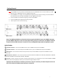
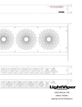
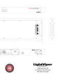
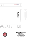
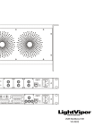
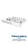
USER MANUAL FOR DMX4i / DMX4o Lighting Control Multiplexer This page intentionally left blank Warning for Your Protection 1. Read these instructions 2. Keep these instructions 3. Heed all warnings 4. Follow all instructions 5. Do not use this apparatus near water. 6. Clean only with a dry cloth. 7. Do not block any of the ventilation openings. Install in accordance with the manufacturer’s instructions. 8. Do not install near any heat sources such as radiators, heat registers, stoves, or other apparatus (including amplifiers) that produce heat. 9. Do not defeat the safety purpose of the polarized or grounding-type plug. A polarized plug has two blades with one wider than the other. A grounding type plug has two blades and a third grounding prong. The wide blade or the third prong are provided for your safety. If the provided plug does not fit into your outlet, consult an electrician for replacement of the obsolete outlet. 10. Protect the power cord from being walked on or pinched, particularly at plugs, convenience receptacles, and the point where they exit from the apparatus. 11. Only use attachments/accessories specified by the manufacturer. 12. Use only with the cart, stand, tripod, bracket, or table specified by the manufacturer, or sold with the apparatus. When a cart is used, use caution when moving the cart/apparatus combination to avoid injury from tip-over. 13. Unplug this apparatus during lightning storms or when unused for long periods of time. 14. Refer all servicing to qualified service personnel. Servicing is required when the apparatus has been damaged in any way, such as power-supply cord or plug is damaged, liquid has been spilled or objects have fallen into the apparatus, the apparatus has been exposed to rain or moisture, does not operate normally, or has been dropped. The apparatus shall not be exposed to dripping or splashing. No objects filled with liquids, such as vases, shall be placed on the apparatus. “WARNING To reduce the risk of fire or electric shock, do not expose this apparatus to rain or moisture.” General Installation Instructions Please consider besides these general instructions also any product-specific instructions in the “Installation” chapter of this manual. 1 Registration Be sure to register your LightViper product, either by filling in the enclosed Registration Card or by completing the on-line registration form at our Web site: http://lightviper.com/register.aspx If you do so, FiberPlex can contact you with any update information. As enhancements and upgrades are developed, you will be contacted at the registration address. Please read this manual - if you call for technical support, we’ll assume that you have. Please address any inquiries to your dealer or directly to FiberPlex at: FiberPlex Inc. 10840-412 Guilford Rd. Annapolis Junction, MD 20701 301.604.0100 Fax: 301.604.0773 [email protected] Limited Lifetime Warranty (US Domestic Only) FiberPlex products are warranted against defects in material and workmanship for their lifetime. This warranty covers the original purchaser only and is not transferable. The lifetime of a product is defined as the period during which the product is manufactured, or can be repaired. FiberPlex will, at its discretion, repair or replace a defective product. FiberPlex warrants that its software and firmware, designed by FiberPlex for use with an instrument will execute its programming instructions when properly installed on that instrument. FiberPlex does not warrant that the operation of the instrument, the software, or the firmware will be uninterrupted or error free. FiberPlex’s products are not authorized for use as critical components in life support devices or systems without the express written approval of the president of FiberPlex, Inc. This warranty does not cover damage from acts of God, accident, abuse, neglect, contamination, unauthorized modification or misuse, operation outside of the environmental specifications for the product, improper site preparation or maintenance, or abnormal conditions of handling. This would include over-voltage failures, and conditions outside of the products specified ratings, problems with buyer-supplied software or interfacing, or normal wear and tear of mechanical components. To return a defective product, please contact our Sales Department for a Return Materials Authorization number (RMA), by calling 301-604-0100, or email: [email protected] Failure to properly package and protect the product during shipping may void this warranty. The RMA number must be written on the outside of the carton. We cannot accept delivery of any equipment that is sent to us without an RMA number. The Buyer shall prepay shipping charges to FiberPlex, and FiberPlex shall pay the return shipping charges. The remedies provided herein are the buyer’s sole and exclusive remedies. FiberPlex shall not be liable for any direct, indirect, special, incidental, or consequential damages. Service The LightViper equipment contains no user-serviceable components: refer to qualified service personnel for repair or upgrade. Your warranty will be voided if you tamper with the internal components. If you have any questions with regard to the above, please contact FiberPlex. In the event your LightViper equipment needs to be upgraded or repaired, it is necessary to contact FiberPlex prior to shipping, and a Return Materials Authorization (RMA) number will be assigned. This number will serve as a reference for you and helps facilitate and expedite the return process. FiberPlex requires that shipments be pre-paid and insured —unless otherwise authorized in advance. IMPORTANT: ANY SHIPMENT THAT IS NOT PRE-PAID OR IS SENT WITHOUT AN RMA NUMBER WILL NOT BE ACCEPTED. Disposal 2 Disposal of Packing Materials The packing materials have been selected with environmental and disposal issues in mind. All packing material can be recycled. Recycling packing saves raw materials and reduces the volume of waste. If you need to dispose of the transport packing materials, please try to use recyclable means. Disposal of Used Equipment Used equipment contains valuable raw materials as well as materials that must be disposed of professionally. Please return your used equipment via an authorized specialist dealer or via the public waste disposal system, ensuring any material that can be recycled is. Please take care that your used equipment cannot be abused. After having disconnected your used equipment from the mains supply, make sure that the mains connector and the mains cable are made useless. Declarations of Conformity Class A Equipment - FCC Notice This equipment has been tested and found to comply with the limits for a Class A digital device, pursuant to Part 15 of the FCC Rules. These limits are designed to provide a reasonable protection against harmful interference when the equipment is operated in a commercial environment. This equipment generates, uses, and can radiate radio frequency energy and, if not installed and used in accordance with the instruction manual, may cause harmful interference to radio communications. Operation of this equipment in a residential area is likely to cause harmful interference, in which case the user will be required to correct the interference at his own expense. Disclaimer The information in this document has been carefully checked and is believed to be accurate at the time of publication. However, no responsibility is taken by us for inaccuracies, errors, or omissions, nor is any liability assumed for any loss or damage resulting either directly or indirectly from use of the information contained within it. 3 Introduction Congratulations on your purchase of a LightViper system. LightViper products are designed, engineered and manufactured by FiberPlex Inc., experts in fiber optics with decades of experience. Our work in audio and data communications products is known in US government applications worldwide. LightViper products combine our pioneering technology with the highest standards in audio engineering. The LightViper System You have purchased the LightViper DMX4. Instead of traditional heavy multi-conductor copper cable, LightViper fiber optic systems utilize lightweight, flexible, military tactical grade fiber-optic cable or duplex PVC and plenum rated fiber for installation use. The DMX4i and DMX4o units allow you send (4) universes of DMX lighting control through your LightViper snake system (FOH to Stage only) via the same fiber-optic cable that carries your (8) audio returns. The Fiber Advantage Fiber optics offer many advantages over copper: Transmits light rather than electrons Transmission over greater distances (more than 2 Km [1.25 mile]) Complete electrical isolation Immunity to RFI and EMI Eliminates ground loop problems Can be routed overhead, through walls, or underground Avoids foot traffic while maintaining aesthetics Functional Considerations The Light Viper DMX4 is an accessory item intended for use with any LightViper 1832, 4832 or 1808 system. These units will only work when properly connected to an existing LightViper fiber-optic system. The LightViper DMX4 units contain no user serviceable parts. Please contact Fiberplex directly with any service issues. Standard Components DMX4i — The DMX4i contains (4) 3-pin female XLR connectors (inputs), (4) 5-pin female XLR connectors (inputs), a single female DB9 connector (inputs), and a single RJ45 EtherCon™ connector. All DMX control inputs are connected to this unit. DMX4o – The DMX4o contains (4) 3-pin male XLR connectors (outputs), (4) 5-pin male XLR connectors (outputs), a single male DB9 connector (output), and a single RJ45 EtherCon™ connector. All DMX control inputs are connected to this unit. DMX interface cables – DMX cables are required to input DMX control into the DMX4i and output DMX control from the DMX4o. These cables are not supplied with the DMX4 units and can be purchased separately from your local lighting or music retailer. The DMX4i and DMX4o can use either (3) pin or (5) pin DMX cables. This system offers ONE WAY control only – from FOH to stage. CAT5 Jumpers – CAT5 jumpers are required to connect the DMX4i and DMX4o to the LightViper transport system. These jumpers are not supplied with the DMX4 units. We recommend “Ruggedized” CAT5 connectors be used in situations where these cables may be prone to being stepped on or pulled while in use. 4 Getting Started To connect & use your DMX4 units please follow these steps: 3.1. Place the DMX4i as near as possible to the VIM-1832 mixer box or VIM-MY32S cards. Connect the DMXi to your VIM1832 mixer box or VIM-MY32S cards using “ruggedized” CAT5 cable. 2. Place the DMX4o unit on stage as near as possible to the lighting fixtures you will be controlling. Connect the DMXo to your VIS-1832 mixer box, VIS-4832 or VIM-0808 unit using “ruggedized” CAT5 cable. 3. Connect the DMX control between the lighting controller and the DMX4i. 4. Connect the DMX4o to the lighting fixtures being controlled. 5. Test the system to ensure control is working 1 2 3 4 5 1 2 3 4 5 DMX4i (Input) DMX4o (Output) Note: The DMX4i and DMX4o are identical with the exception that DMX is input to the DMX4i and output from the DMX4o. With that in mind, the description below pertains to both units. The DMX4o is identical except the XLR and DB9 connectors are female as it is providing DMX output from the LightViper system. DMX4i/DMX4o 1 (3) pin XLR connectors - This is where the DMX control is input into DMX4i and output from the DMX4o. 2 (5) pin XLR connectors - This is alternatively where the DMX control is input into the DMX4i and output from the DMX4o. 3 DB9 Connector – This is where the Yamaha control protocol can be input to the DMX4i and output from the DMX4o via a 9 pin crossover cable. 4 RJ45 EtherCon™ Connector – This connector provides the interface between the DMX4i and the VIM-1832, VIM-MY32S or VIM-1808, and between the DMX4o and the VIS-1832, VIS-4832 or VIM-0808. 5 Sync LED – This LED is unlit when no AC power is present and green when the unit is powered and in sync. Both the DMX4i and DMX4o receive their power from the LightViper units they are connected to through this RJ45 connector. Important: Each channel has a selection of connectors. Only one connector per channel may be used at one time. This includes the D9 HA control connector on channel 4. 5 LightViper DMX4i / DMX4o Specifications 1. General Specifications Operating Temp 0 to +50°C ambient temperature. Sync LED LED (green) indicates the RJ45 link is OK, LED (red) indicates problem with RJ45 link, LED (off) indicates no power. AC Power N/A Max Current Rating VIM-MY32M Control RJ-45 connector for logic level control, CMOS or TTL at 2 MHz max per channel. DMX Data Single Direction, fully complies with the USITT DMX512 Specification Dimensions DMX4 1 Rack Unit X 6.5" (165mm) Deep Weight DMX4 9 lbs (4 Kg) Packed for shipment 3.5 W from RJ45 host unit DMX Connector Pin Outs 3 Pin XLR (typ M/F) 5 Pin XLR (typ M/F) 1. 2. 3. 1. 2. 3. 4. 5. Gnd Data Data + Gnd Data Data + N/C N/C HA Connector Pin Outs 1. 2. 3. 4. 5. 6. 7. 8. 9. Unused RX TX TX + Ground RX + Unused Unused Unused Control Circuits RJ-45 Pin Outs 1. 2. 3. 4. 5. 6. 7. 8. 6 GND TX1 TX2 TX3 RX1 RX2 RX3 VCC +5VDC This page intentionally left blank 8 LVDXUM 6/2007