1
D-Link DFL-1500
VPN/Firewall Router
User Manual
D-Link
Building Networks for People
© Copyright 2003 D-Link Systems, Inc. All rights reserved.
No part of this publication including text, examples, diagrams or illustrations may be reproduced, transmitted, or translated in any
form or by any means, electronic, mechanical, manual, optical or otherwise, for any purpose, without prior written permission of
D-Link Systems, Inc.
DFL-1500 User Manual
Version 2.000
September 15, 2004
Trademarks
Products mentioned in this document are trademarks or registered trademarks of their respective holders.
Regulatory Compliance
FCC Class A Part 15 CSA/CUS
II
Table of Contents
Part I
Overview...............................................................................................................................................2
Chapter 1 Quick Start ...........................................................................................................................................3
1.1
1.2
1.3
1.4
1.5
1.6
1.6.1
1.6.2
Check Your Package Contents...................................................................................................................................3
Five steps to configure DFL-1500 quickly ................................................................................................................3
Wiring the DFL-1500 ................................................................................................................................................5
Default Settings and architecture of DFL-1500 .........................................................................................................6
Using the Setup Wizard .............................................................................................................................................8
Internet Connectivity ...............................................................................................................................................11
LAN1-to-WAN1 Connectivity.......................................................................................................................11
WAN1-to-DMZ1 Connectivity ......................................................................................................................13
Chapter 2 System Overview ...............................................................................................................................16
2.1
2.2
2.2.1
2.2.2
2.3
2.3.1
2.3.2
Typical Example Topology......................................................................................................................................16
Changing the LAN1 IP Address ..............................................................................................................................17
From LAN1 to configure DFL-1500 LAN1 network settings........................................................................17
From CLI (command line interface) to configure DFL-1500 LAN1 network settings ..................................18
The design principle.................................................................................................................................................19
Web GUI design principle..............................................................................................................................19
Rule principle .................................................................................................................................................19
Part II Basic Configuration ............................................................................................................................21
Chapter 3 Basic Setup.........................................................................................................................................23
3.1
3.2
3.3
3.4
3.4.1
3.4.2
3.4.3
Demand....................................................................................................................................................................23
Objectives ................................................................................................................................................................23
Methods ...................................................................................................................................................................23
Steps.........................................................................................................................................................................23
Setup WAN1 IP..............................................................................................................................................23
Setup DMZ1, LAN1 Status ............................................................................................................................25
Setup WAN1 IP alias .....................................................................................................................................27
Chapter 4 System Tools ......................................................................................................................................29
4.1
4.2
4.3
4.4
4.4.1
4.4.2
4.4.3
4.4.4
4.4.5
4.4.6
Demand....................................................................................................................................................................29
Objectives ................................................................................................................................................................29
Methods ...................................................................................................................................................................29
Steps.........................................................................................................................................................................33
General settings ..............................................................................................................................................33
DDNS setting .................................................................................................................................................36
DNS Proxy setting..........................................................................................................................................37
DHCP Relay setting .......................................................................................................................................37
SNMP Control................................................................................................................................................38
Change DFL-1500 interface ...........................................................................................................................39
Chapter 5 Remote Management .........................................................................................................................41
5.1
5.2
5.3
Demands ..................................................................................................................................................................41
Methods ...................................................................................................................................................................41
Steps.........................................................................................................................................................................42
I
5.3.1
5.3.2
5.3.3
5.3.4
Telnet..............................................................................................................................................................42
WWW ............................................................................................................................................................42
SNMP.............................................................................................................................................................42
ICMP ..............................................................................................................................................................43
Chapter 6 Authentication ....................................................................................................................................44
6.1
6.2
6.3
6.3.1
6.3.2
6.3.3
6.3.4
6.3.5
6.3.6
Demands ..................................................................................................................................................................44
Methods ...................................................................................................................................................................44
Steps.........................................................................................................................................................................44
Local Setting ..................................................................................................................................................44
PoP3(s) Setting...............................................................................................................................................46
Imap(s) Setting ...............................................................................................................................................46
Radius Setting ................................................................................................................................................46
LDAP Setting .................................................................................................................................................47
Exempt Host...................................................................................................................................................47
Part III NAT、Routing & Firewall .................................................................................................................48
Chapter 7 NAT....................................................................................................................................................49
7.1
7.2
7.3
7.4
7.4.1
7.4.2
7.5
7.5.1
7.5.2
7.5.3
7.5.4
7.5.5
Demands ..................................................................................................................................................................49
Objectives ................................................................................................................................................................50
Methods ...................................................................................................................................................................50
Steps.........................................................................................................................................................................51
Setup Many-to-one NAT rules .......................................................................................................................51
Setup Virtual Server for the FtpServer1 .........................................................................................................55
NAT modes introduction .........................................................................................................................................57
Many-to-One type ..........................................................................................................................................57
Many-to-Many type........................................................................................................................................58
One-to-One type .............................................................................................................................................59
One-to-One (bidirectional) type .....................................................................................................................59
NAT modes & types.......................................................................................................................................60
Chapter 8 Routing...............................................................................................................................................61
8.1
8.2
8.3
8.4
8.4.1
8.4.2
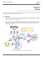
Demands ..................................................................................................................................................................61
Objectives ................................................................................................................................................................62
Methods ...................................................................................................................................................................62
Steps.........................................................................................................................................................................62
Add a static routing entry ...............................................................................................................................62
Add a policy routing entry..............................................................................................................................64
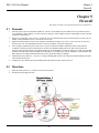
Chapter 9 Firewall ..............................................................................................................................................67
9.1
9.2
9.3
9.4
9.4.1
9.4.2
9.4.3
9.4.4
9.4.5
9.4.6
Demands ..................................................................................................................................................................67
Objectives ................................................................................................................................................................67
Methods ...................................................................................................................................................................68
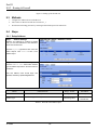
Steps.........................................................................................................................................................................68
Setup Address.................................................................................................................................................68
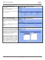
Setup Service..................................................................................................................................................70
Setup Schedule ...............................................................................................................................................72
Setup IP/MAC binding...................................................................................................................................73
Block internal PC session (LAN à WAN)....................................................................................................75
Setup Alert detected attack.............................................................................................................................78
II
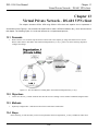
Part IV Virtual Private Network......................................................................................................................80
Chapter 10 VPN Technical Introduction ............................................................................................................81
10.1
10.2
10.2.1
10.2.2
10.2.3
10.2.4
10.2.5
10.2.6
10.2.7
10.3
VPN benefit .............................................................................................................................................................81
Related Terminology Explanation ...........................................................................................................................81
VPN................................................................................................................................................................81
IPSec ..............................................................................................................................................................81
Security Association.......................................................................................................................................81
IPSec Algorithms ...........................................................................................................................................81
Key Management ...........................................................................................................................................82
Encapsulation .................................................................................................................................................83
IPSec Protocols ..............................................................................................................................................83
Make VPN packets pass through DFL-1500 ...........................................................................................................84
Chapter 11 Virtual Private Network – IPSec ......................................................................................................85
11.1
11.2
11.3
11.4
Demands ..................................................................................................................................................................85
Objectives ................................................................................................................................................................85
Methods ...................................................................................................................................................................85
Steps.........................................................................................................................................................................86
□
DES/MD5 IPSec tunnel: the IKE way ...........................................................................................................86
□
DES/MD5 IPSec tunnel: the Manual-Key way ..............................................................................................95
Chapter 12 Virtual Private Network –Dynamic IPSec .....................................................................................102
12.1
12.2
12.3
12.4
Demands ................................................................................................................................................................102
Objectives ..............................................................................................................................................................102
Methods .................................................................................................................................................................102
Steps.......................................................................................................................................................................103
Chapter 13 Virtual Private Network – DS-601 VPN client ..............................................................................109
13.1
13.2
13.3
13.4
Demands ................................................................................................................................................................109
Objectives ..............................................................................................................................................................109
Methods .................................................................................................................................................................109
Steps.......................................................................................................................................................................109
Chapter 14 Virtual Private Network – Hub and Spoke VPN............................................................................121
14.1
14.2
14.3
14.4
Demands ................................................................................................................................................................121
Objectives ..............................................................................................................................................................121
Methods .................................................................................................................................................................121
Steps.......................................................................................................................................................................122
Chapter 15 Virtual Private Network – PPTP ....................................................................................................127
15.1
15.2
15.3
15.4
Demands ................................................................................................................................................................127
Objectives ..............................................................................................................................................................127
Methods .................................................................................................................................................................127
Steps.......................................................................................................................................................................128
15.4.1
Setup PPTP Network Server ........................................................................................................................128
15.4.2
Setup PPTP Network Client .........................................................................................................................129
Chapter 16 Virtual Private Network – L2TP ....................................................................................................131
16.1
16.2
16.3
Demands ................................................................................................................................................................131
Objectives ..............................................................................................................................................................131
Methods .................................................................................................................................................................131
III
16.4
Steps.......................................................................................................................................................................132
16.4.1
Setup L2TP Network Server ........................................................................................................................132
Part V Content Filters ..................................................................................................................................136
Chapter 17 Content Filtering – Web Filters......................................................................................................137
17.1
17.2
17.3
17.4
17.5
Demands ................................................................................................................................................................137
Objectives ..............................................................................................................................................................138
Methods .................................................................................................................................................................138
Steps.......................................................................................................................................................................139
Setting priorities.....................................................................................................................................................144
Chapter 18 Content Filtering – Mail Filters .....................................................................................................147
18.1
18.2
18.3
18.4
18.5
Demands ................................................................................................................................................................147
Objectives ..............................................................................................................................................................147
Methods .................................................................................................................................................................147
Steps for SMTP Filters ..........................................................................................................................................148
Steps for POP3 Filters............................................................................................................................................149
Chapter 19 Content Filtering – FTP Filtering...................................................................................................151
19.1
19.2
19.3
19.4
Demands ................................................................................................................................................................151
Objectives ..............................................................................................................................................................151
Methods .................................................................................................................................................................151
Steps.......................................................................................................................................................................152
Part VI Intrusion Detection System ..............................................................................................................156
Chapter 20 Intrusion Detection Systems ..........................................................................................................157
20.1
20.2
20.3
20.4
Demands ................................................................................................................................................................157
Objectives ..............................................................................................................................................................157
Methods .................................................................................................................................................................157
Steps.......................................................................................................................................................................158
Part VII
Bandwidth Management、High Availability ...........................................................................160
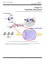
Chapter 21 Bandwidth Management ................................................................................................................161
21.1
21.2
21.3
21.4
Demands ................................................................................................................................................................161
Objectives ..............................................................................................................................................................162
Methods .................................................................................................................................................................163
Steps.......................................................................................................................................................................164
21.4.1
Inbound Traffic Management.......................................................................................................................164
21.4.2
Outbound Traffic Management ....................................................................................................................169
Chapter 22 High Availability ............................................................................................................................171
22.1
22.2
22.3
22.4
Demands ................................................................................................................................................................171
Objectives ..............................................................................................................................................................171
Methods .................................................................................................................................................................172
Steps.......................................................................................................................................................................172
22.4.1
Setup High Availability................................................................................................................................172
Part VIII
System Maintenance.................................................................................................................174
Chapter 23 System Status .................................................................................................................................175
23.1
23.2
23.3
Demands ................................................................................................................................................................175
Objectives ..............................................................................................................................................................175
Methods .................................................................................................................................................................175
IV
23.4
Steps.......................................................................................................................................................................175
Chapter 24 Log System ....................................................................................................................................179
24.1
24.2
24.3
24.4
Demands ................................................................................................................................................................179
Objectives ..............................................................................................................................................................179
Methods .................................................................................................................................................................179
Steps.......................................................................................................................................................................179
24.4.1
System Logs .................................................................................................................................................179
24.4.2
Syslog & Mail log ........................................................................................................................................180
Chapter 25 System Maintenance ......................................................................................................................183
25.1
25.2
25.3
25.4
25.5
Demands ................................................................................................................................................................183
Steps for TFTP Upgrade ........................................................................................................................................183
Steps for Firmware upgrade from Web GUI..........................................................................................................184
Steps for Database Update from Web GUI............................................................................................................185
Steps for Factory Reset ..........................................................................................................................................186
25.5.1
Step for factory reset under web GUI...........................................................................................................186
25.5.2
Step for NORMAL factory reset ..................................................................................................................186
25.5.3
Steps for EMERGENT factory reset ............................................................................................................186
25.6
Save the current configuration ...............................................................................................................................187
25.7
Steps for Backup / Restore Configurations............................................................................................................187
25.8
Steps for Reset password .......................................................................................................................................188
Appendix...........................................................................................................................................................190
Appendix A Command Line Interface (CLI) ................................................................................................191
A.1
Enable the port of DFL-1500............................................................................................................191
A.2
CLI commands list (Normal Mode) .................................................................................................191
A.3
CLI commands list (Rescue Mode) ..................................................................................................193
Appendix B Trouble Shooting ......................................................................................................................195
Appendix C System Log Syntax ...................................................................................................................201
Appendix D Glossary of Terms.....................................................................................................................209
Appendix E Index .........................................................................................................................................211
Appendix F Hardware...................................................................................................................................212
Appendix G Version of Software and Firmware ...........................................................................................215
Appendix H Customer Support .....................................................................................................................217
V
Part I
Overview
Part I
Overview
D-Link
2
DFL-1500 User Manual
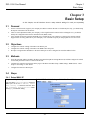
Chapter 1
Quick Start
Chapter 1
Quick Start
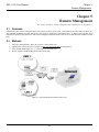
This chapter introduces how to quick setup the DFL-1500.
DFL-1500 is an integrated all-in-one solution that can facilitate the maximum security and the best resource utilization for
the enterprises. It contains a high-performance stateful packet inspection (SPI) Firewall, policy-based NAT, ASIC-based
wire-speed VPN, upgradeable Intrusion Detection System, Dynamic Routing, Content Filtering, Bandwidth
Management, WAN Load Balancer, High Availability and other solutions in a single box. It is one of the most
cost-effective all-in-one solutions for enterprises.
1.1
Check Your Package Contents
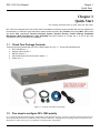
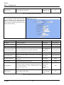
These are the items included with your DFL-1500 purchase as Figure 1-1. They are the following items
1. DFL-1500 Device * 1
2. Ethernet cable (RJ-45) * 1
3. RS-232 console * 1
4. CD (include User's manual and Quick Guide) * 1
5. Power cord * 1
Figure 1-1 All items in the DFL-1500 package
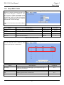
1.2
Five steps to configure DFL-1500 quickly
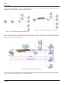
Let’s look at the common network topology without DFL-1500 applying like Figure 1-2. This is a topology which is almost used by
all the small/medium business or SOHO use as their internet connectivity. Although that your topology is not necessarily the same
diagram below, but it still can give you a guideline to configure DFL-1500 quickly.
3
Part I
Overview
Now you can pay attention at the IP Sharer in the diagram. The IP Sharer can provide you with NAT (Network Address
Translation), PAT (Port Address Translation) and other functions.
Figure 1-3 The example after DFL-1500 applies on it
Figure 1-2 The example before DFL-1500 applies on it
Here we would like to alter the original IP Sharer with the DFL-1500 like Figure 1-3. If we hope to have DFL-1500 to replace the IP
Sharer, we just need to simply execute the following five steps as Figure 1-4 showed. By these steps, we hope to build an image to
tell you how to let DFL-1500 work basically.
Figure 1-4 Five steps to configure DFL-1500
As the Figure 1-4 illustrated, with the five-step configurations, DFL-1500 will have the same functions with the original IP Sharer.
Please see the following description of the five-step configurations.
D-Link
4
DFL-1500 User Manual
Chapter 1
Quick Start
1.
Setup:
Install three physical lines inclusive of the power cord, outbound link (connected WAN1 port) and inbound direction
(connected LAN1 port). For the details, please refer section 1.3.
Continually, we will connect to the web GUI of DFL-1500. So you must make sure that you have a PC which is located in the
same subnet with DFL-1500 before this step. Note: The default LAN1 port is (192.168.1.254 / 255.255.255.0). Refer to
section 1.5 for more information.
2.
LAN:
Configure the LAN1 port of DFL-1500. You can refer to section 1.4 for the default network configurations of DFL-1500.
Note: If you were connected from LAN1 port and changed the LAN1 IP address settings of DFL-1500. The network will be
disconnected since the IP address is different between your pc and DFL-1500 LAN1 port.
3.
WAN:
Configure the WAN1 port of DFL-1500. You can refer to section 1.4 for the default network configurations of DFL-1500.
4.
NAT:
Configure the connection of LAN to WAN direction. It will make all the client pc access the internet through DFL-1500. For
more information, please refer to section 1.6.1.
5.
Virtual Server:
If there is any server located inside the DFL-1500. You may hope these servers can provide services outside. So you should
configure the Virtual Server which provides connections of WAN to LAN direction. For more information, please refer to
section 1.6.2.
After you completely finished the above steps, the connectivity function of DFL-1500 is probably well-done.
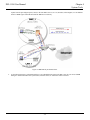
1.3
Wiring the DFL-1500
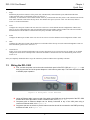
A. First, connect the power cord to the socket at the back panel of the DFL-1500 as in Figure 1-5 and
then plug the other end of the power adapter to a wall outlet or power strip. The Power LED will turn ON
to indicate proper operation.
Figure 1-5 Back panel of the DFL-1500
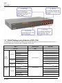
B. Using an Ethernet cable, insert one end of the cable to the WAN port on the front panel of the DFL-1500
and the other end of the cable to a DSL or Cable modem, as in Figure 1-6.
C. Computers with an Ethernet adapter can be directly connected to any of the LAN ports using a
cross-over Ethernet cable, as in Figure 1-6.
D. Computers that act as servers to provide Internet services should be connected to the DMZ port using
an Ethernet Cable, as in Figure 1-6.
5
Part I
Overview
Figure 1-6 Front end of the DFL-1500
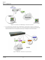
1.4
Default Settings and architecture of DFL-1500
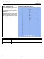
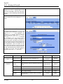
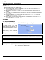
You should have an Internet account already set up and have been given most of the following information as Table 1-1.
Fill out this table when you edit the web configuration of DFL-1500.
Items
Default value
Password:
admin
Fixed IP
WAN1
(Port 1)
IP Address
____.____.____.____
Subnet Mask
____.____.____.____
Gateway IP
____.____.____.____
Primary DNS
____.____.____.____
Not initialized
Secondary DNS
PPPoE
New value
____.____.____.____
PPPoE Username
____.____.____.____
PPPoE Password
____.____.____.____
DHCP
WAN2
(Port 2)
IP Address
Fixed IP
D-Link
Not initialized
____.____.____.____
Subnet Mask
____.____.____.____
Gateway IP
____.____.____.____
Primary DNS
____.____.____.____
Secondary DNS
____.____.____.____
6
DFL-1500 User Manual
PPPoE
Chapter 1
Quick Start
PPPoE Username
____.____.____.____
PPPoE Password
____.____.____.____
DHCP
DMZ1(Port 3)
LAN1(Port 4)
LAN2(Port 5)
IP Address
10.1.1.254
____.____.____.____
IP Subnet Mask
255.255.255.0
____.____.____.____
IP Address
192.168.1.254
____.____.____.____
IP Subnet Mask
255.255.255.0
____.____.____.____
IP Address
192.168.2.254
____.____.____.____
IP Subnet Mask
255.255.255.0
____.____.____.____
Table 1-1 DFL-1500 related network settings
Figure 1-7 The default settings of DFL-1500
As the above diagram Figure 1-7 illustrated, this diagram shows the default topology of DFL-1500. And you can configure
the DFL-1500 by connecting to the LAN1_IP (192.168.1.254) from the PC1_1 (192.168.1.1). In the following sections, we
will teach you how to quickly setup the DFL-1500 in the basic appliances.
7
Part I
Overview
1.5
Using the Setup Wizard
A computer on your LAN1 must be assigned an IP address and Subnet Mask from the same range as the IP address and
Subnet Mask assigned to the DFL-1500 in order to be able to make an HTTPS connection using a web browser. The
DFL-1500 is assigned an IP address of 192.168.1.254 with a Subnet Mask of 255.255.255.0 by default. The computer
that will be used to configure the DFL-1500 must be assigned an IP address between 192.168.1.1 and 192.168.1.253
with a Subnet Mask of 255.255.255.0 to be able to connect to the DFL-1500. This address range can be changed later.
There are instructions in the DFL-1500 Quick Installation Guide, if you do not know how to set the IP address and Subnet
Mask for your computer.
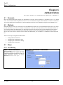
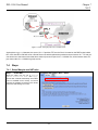
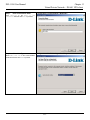
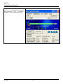
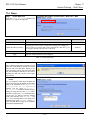
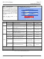
Step 1.
Login
Connect to https://192.168.1.254
Type “admin” in the account field, “admin” in
the Password field and click Login.
Note: Please do not access web UI through
proxy, or the login may be locked by others or
the original user.
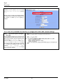
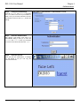
Step 2.
Click the Run Setup Wizard.
Run Setup Wizard
After login to https://192.168.1.254
BASIC SETUP > Wizard
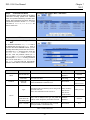
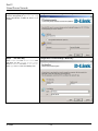
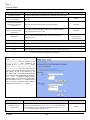
Step 3.
BASIC SETUP > Wizard
System Name
Enter the Host Name and the Domain Name,
followed by clicking the Next.
D-Link
8
DFL-1500 User Manual
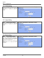
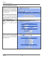
Step 4.
Operation Mode
Chapter 1
Quick Start
BASIC SETUP > Wizard > Next
DFL-1500 VPN/Firewall Router can operate in
NAT/Router mode or Transparent mode.
Choose which operation Mode for this device to
use.
NAT/Route mode
Transparent mode
In NAT/Route mode, you can create NAT mode rules and Route mode rules. For the related information, please
refer to Chapter 6 and Chapter 7.
Ÿ NAT mode rules use network address translation to hide the addresses in a more secure network from users
in a less secure network.
Ÿ Route mode rules accept or deny connections between networks without performing address translation.
Transparent mode provides the same basic protection as NAT mode. Packets received by the DFL-1500 are
intelligently forwarded or blocked according to firewall rules. The DFL-1500 can be inserted in your network at
any point without the need to make any changes to your network or any of its components. However, VPN, NAT,
Routing and some advanced firewall features (such as Authentication, IP/MAC Binding) are only available in
NAT/Route mode.
Note:
1. You cannot connect the LAN1/LAN2/DMZ interfaces to the same Hub while using Transparent mode,
otherwise the traffic from the PCs under LAN1/LAN2/DMZ interfaces may be blocked.
2. If you would like to change the operation mode from NAT/Route mode to Transparent mode, you have to
backup the configuration file and then do the factory reset first.
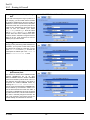
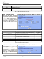
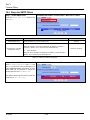
Step 5.
WAN Connectivity
BASIC SETUP > Wizard > Next > WAN1 IP
Choose the type of IP Address Assignment
provided by your ISP to access the Internet.
Here we have four types to select. This will
determine how the IP address of WAN1 is
obtained. Click Next to proceed.
9
Part I
Overview
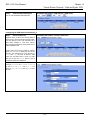
Step 5.a —
DHCP client
BASIC SETUP > Wizard > Next > DHCP
If Get IP Automatically (DHCP) is
selected, DFL-1500 will request for IP address,
netmask, and DNS servers from your ISP. You
can use your preferred DNS by clicking the DNS
IP Address and then completing the Primary
DNS and Secondary DNS server IP addresses.
Click Next to proceed.
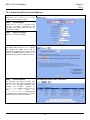
Step 5.b —
Fixed IP
BASIC SETUP > Wizard > Next > Fixed IP
If Fixed IP Address is selected, enter the
ISP-given IP Address, Subnet Mask,
Gateway IP, Primary DNS and Secondary
DNS IP. Click Next to proceed.
Step 5.c —
PPPoE client
BASIC SETUP > Wizard > Next > PPPoE
If PPP over Ethernet is selected, enter the
ISP-given User Name, Password and the
optional Service Name. Click Next to
proceed.
D-Link
10
DFL-1500 User Manual
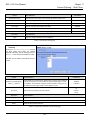
Step 5.d —
Chapter 1
Quick Start
Alert Message
Please Note that an alert message box “When
changing to none fixed ip mode, system
will delete all ip alias!” will appear
while you change Get IP Automatically
(DHCP) or PPP over Ethernet but not Fixed
IP Address as your WAN link.
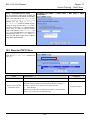
Step 6.
System Status
BASIC SETUP > Wizard > Run Setup Wizard > Next > Next
Here we select Fixed IP method in WAN1
port. Then the DFL-1500 provides a short
summary of the system. Please check if
anything mentioned above is properly set into
the system. Click Finish to close the wizard.
1.6
Internet Connectivity
After setting up DFL-1500 with the wizard, DFL-1500 can connect to the ISP. In this chapter, we introduce LAN1-to-WAN1
Connectivity to explain how the computers under LAN1 can access the Internet at WAN1 through DFL-1500. Subsequently, we
introduce WAN1-to-DMZ1 Connectivity to explain how the servers under DMZ1 can be accessed by the LAN1 users and other
Internet users on the WAN1 side.
You MUST press Apply to proceed to the next page. Once applying any changes, the settings are immediately
updated into the flash memory.
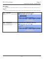
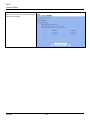
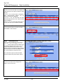
1.6.1 LAN1-to-WAN1 Connectivity
The LAN Settings page allows you to modify the IP address and Subnet Mask that will identify the DFL-1500 on your LAN. This is
the IP address you will enter in the URL field of your web browser to connect to the DFL-1500. It is also the IP address that all of
the computers and devices on your LAN will use as their Default Gateway.
11
Part I
Overview
Step 1.
Device IP Address
BASIC SETUP > LAN Settings > LAN1 Status
Setup the IP Address and IP Subnet Mask
for the DFL-1500.
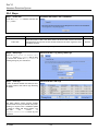
Step 2.
Client IP Range
Enable the DHCP server if you want to use
DFL-1500 to assign IP addresses to the
computers under LAN1. Specify the Pool
Starting Address, Pool Size, Primary
DNS, and Secondary DNS that will be assigned
to them.
Example: in the figure, the DFL-1500 will assign
one IP address from 192.168.1.100 ~
192.168.1.119, together with the DNS server
192.168.1.254, to the LAN1 PC that
requests for an IP address.
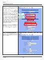
Step 3.
Apply the Changes
Click Apply to save. Now you can enable the
DHCP clients on your LAN1 PCs to get an IP.
Note: The IP Pool Starting Address must be on the same subnet specified in
the IP Address and the IP Subnet Mask field. For example, the addresses given
by the 192.168.1.100 with a pool size of 20 (192.168.1.100 ~
192.168.1.119) are all within the same range of 192.168.1.254 /
255.255.255.0
Step 4.
ADVANCED SETTINGS > NAT > Status
Check NAT Status
The default setting of NAT is in Basic Mode.
After completing Step 3, the NAT is
automatically configured related rules to let all
private-IP LAN/DMZ-to-WAN requests to be
translated with the public IP assigned by the
ISP.
Step 5.
Check NAT Rules
ADVANCED SETTINGS > NAT > NAT Rules
The DFL-1500 has added the NAT rules as the
right diagram. The rule Basic-LAN1 means
that, when matching the condition (requests of
LAN/DMZ-to-WAN direction with its source IP
falling in the range of 192.168.1.254 /
255.255.255.0), the request will be
translated into a public-source-IP requests, and
then be forwarded to the destinations.
D-Link
12
DFL-1500 User Manual
Chapter 1
Quick Start
1.6.2 WAN1-to-DMZ1 Connectivity
This section tells you how to provide an FTP service with a server installed under your DMZ1 to the public Internet users. After
following the steps, users at the WAN side can connect to the FTP server at the DMZ1 side.
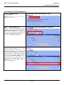
Step 1.
Device IP Address
BASIC SETUP > DMZ Settings > DMZ1 Status
Setup the IP Address and IP Subnet
Mask for the DFL-1500 of the DMZ1
interface.
Step 2.
Client IP Range
Enable the DHCP server if you want to use
DFL-1500 to assign IP addresses to the
computers under DMZ1.
Step 3.
Apply the Changes
Click Apply to save your settings.
Step 4.
Check NAT Status
ADVANCED SETTINGS > NAT > Status
The default setting of NAT is in Basic
Mode. After applying the Step 3, the NAT is
automatically configured related rules to let
all private-IP LAN/DMZ-to-WAN requests to
be translated with the public IP assigned by
the ISP.
Step 5.
Check NAT Rules
ADVANCED SETTINGS > NAT > NAT Rules
The DFL-1500 has added the NAT rules as
the right diagram. The rule Basic-DMZ1
(number 1) means that, when matching the
condition (requests of LAN/DMZ-to-WAN
direction with its source IP falling in the
range of 10.1.1.254 / 255.255.255.0),
the request will be translated into a
public-source-IP requests, and then be
forwarded to the destinations.
13
Part I
Overview
Step 6.
Setup IP for the FTP
Server
Assign an IP of 10.1.1.5/255.255.255.0 to the FTP server under DMZ1. Assume the
FTP Server is at 10.1.1.5. And it is listening to the well-known port (21).
Step 7.
ADVANCED SETTINGS > NAT > Virtual Servers
Setup Server Rules
Insert a virtual server rule by clicking the
Insert button.
Step 8.
Customize the Rule
ADVANCED SETTINGS > NAT > Virtual Servers > Insert
Customize the rule name as the
ftpServer. For any packets with its
destination IP address equaling to the
WAN1 IP (61.2.1.1) and destination port
equaling to 44444. DFL-1500 will translate
the packet’s destination IP/port into
10.1.1.5/21. Check the Passive FTP
client to maximize the compatibility of the
FTP protocol. This is useful if you want to
provide connectivity to passive FTP clients.
For passive FTP clients, the server at DMZ
will return them the private IP address
(10.1.1.5) and the port number for the
clients to connect back for data
transmissions. Since the FTP clients at the
WAN side cannot connect to a private-IP
(ex.10.1.1.5) through the internet. The data
connections would be fail. After enabling
this feature, the DFL-1500 will translate the
private IP/port into an IP/port of its own.
Thus the problem is gracefully solved.
Step 9.
View the Result
ADVANCED SETTINGS > NAT > Virtual Servers
Now any request towards the DFL-1500’s
WAN1 IP (61.2.1.1) with dest. port
44444 will be translated into a request
towards 10.1.1.5 with port 21, and then
be forwarded to the 10.1.1.5. The FTP
server listening at port 21 in 10.1.1.5 will
pick up the request.
D-Link
14
DFL-1500 User Manual
Step 10. View the NAT Rules
In the previous Step 8, we have already
checked “Auto update to Firewall/NAT
rules when you Apply this page”, so it will
automatically add one NAT rule to transfer
the IP address of virtual server when server
responses packet back to the client.
Chapter 1
Quick Start
ADVANCED SETTINGS > NAT > NAT Rules
15
Part I
Overview
Chapter 2
System Overview
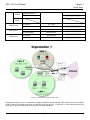
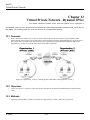
In this chapter, we will introduce the network topology for use with later chapters.
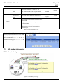
2.1
Typical Example Topology
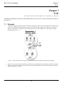
In this chapter, we introduce a typical network topology for the DFL-1500. In Figure 2-1, the left half side is a DFL-1500 with one
LAN, one DMZ, and one WAN link. We will demonstrate the administration procedure in the later chapters by using the below
Figure 2-1.
The right half side contains another DFL-1500 connected with one LAN, one DMZ, and one WAN. You can imagine this is a
branch office of Organization_1. In this architecture, all the users under Organization can access sever reside in the Internet or DMZ
region smoothly. Besides, Organization_1 communicates with Organization_2 with a VPN tunnel established by the two DFL-1500
VPN/Firewall routers. The VPN tunnel secures communications between Organizations more safely.
We will focus on how to build up the topology using the DFL-1500 as the following Figure 2-1. In order to achieve this purpose, we
need to know all the administration procedure.
Figure 2-1 Typical topology for deploying DFL-1500
Continually, we will introduce all the needed administration procedure in the following section.
D-Link
16
DFL-1500 User Manual
Chapter 2
System Overview
1.
Part II Basic Configuration
How to configure the WAN/DMZ/LAN port settings and user authentication.
2.
Part III NAT、Routing & Firewall
Introducing the NAT, Routing, Firewall features.
3.
Part IV Virtual Private Network
If you need to build a secure channel with your branch office, or wish to access the inside company resource as usual while
outside your company, the Virtual Private Network (VPN) function can satisfy you.
4.
Part V Content Filters
If you hope to restrict the web contents, mail attachments, downloaded ftp file from intranet region, try this feature to fit your
requirement.
5.
Part VI Intrusion Detection System
Use the Intrusion Detection System (IDS) to detect all the potential DoS attacks, worms, hackers from Internet.
6.
Part VII Bandwidth Management、High Availability
If you wish to make your inbound/outbound bandwidth utilized more efficiently, you may use the Bandwidth Management
feature to manage your bandwidth.
7.
Part VIII System Maintenance
In this part, we provide some useful skills to help you to justify DFL-1500 more securely and steadily.
2.2
Changing the LAN1 IP Address
The default settings of DFL-1500 are listing in Table 1-1. However, the original LAN1 setting is 192.168.1.254/255.255.255.0
instead of 192.168.40.254/255.255.255.0 as in Figure 2-1. We will change the LAN1 IP of the DFL-1500 to 192.168.40.254.
We provide two normal ways to configure the LAN1 IP address. One is to configure the LAN1 IP from LAN1 port. The other way
is to configure the LAN1 IP through console.
2.2.1 From LAN1 to configure DFL-1500 LAN1 network settings
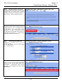
Step 1.
Connect to the DFL-1500
Use an IE at 192.168.1.1 to connect to https://192.168.1.254
Using a network line to connect DFL-1500 with
LAN1 port. The PC which connected to DFL-1500
must be assigned 192.168.1.X address (LAN1
default IP address is 192.168.1.254/24). Type
https://192.168.1.254
or
http://192.168.1.254:8080 to configure the
DFL-1500 in the web browser.
17
Part I
Overview
Step 2.
Setup LAN1 IP information
BASIC SETUP > LAN Settings > LAN1 Status
Enter the IP Address and IP Subnet Mask with
192.168.40.254 / 255.255.255.0 and click
Apply.
Warning: After you apply the changed settings,
the network will be disconnected instantly since
the network IP address you are logining is
changed.
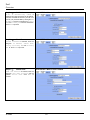
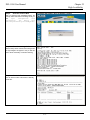
2.2.2 From CLI (command line interface) to configure DFL-1500 LAN1 network settings
Step 1.
Use Console port to configure
DFL-1500
Use the supplied console line to connect the PC
to the Diagnostic RS-232 socket of the DFL-1500.
Start a new connection using the HyperTerminal
with parameters: No Parity, 8 Data bits, 1
stop bit, and baud rate 9600. Enter admin
for user name and admin for password to login.
After logging into DFL-1500, enter the commands
“en“ to enter the privileged mode. Enter the
command
“ip
ifconfig
INTF3
192.168.40.254 255.255.255.0” to change
the IP of the LAN1 interface.
D-Link
18
DFL-1500 User Manual
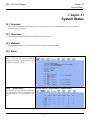
2.3
Chapter 2
System Overview
The design principle
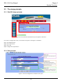
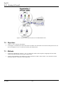
2.3.1 Web GUI design principle
Step 1. Select Main-Function
Step 3. Select Tag
Step 4. Configure the real parameters
Step 2. Select Sub-Function
Figure 2-2 You can select the functional area by the sequence in Web GUI
If we want to configure DFL-1500, we can follow the sequence as the Figure 2-2 illustrated.
Step1. Select Main-function
Step2. Select Sub-function
Step3. Select Tag
Step4. Configure the real parameters
2.3.2 Rule principle
Figure 2-3 The rule configuration is divided into three parts
19
Part I
Overview
You may find many rules configuration in the DFL-1500. They are distributed in the respective feature. These rules include
1.
NAT rule
2.
Virtual Server rule
3.
Firewall rule
4.
Policy route rule
5.
Bandwidth management rule
The behavior of each rule is different, and so are their configuration parameters. But the designed principle of each rule is the same.
The configuration is divided into three parts as Figure 2-3 illustrated. You just need to enter the necessary information onto each
part according to your requirement. As for the definitions of the three-part configuration, please refer to the following description.
1.
Status: Describe the status and name of this rule.
2.
Condition: What kind of characteristics does packet hold? And it will be captured by this rule.
3.
Action: If the packet is captured by this rule? What action will this rule do?
As the Figure 2-4 illustrated, the page of the rule edition is also divided into three parts. Their definitions are also the same as we
have discussed in Figure 2-3.
Additionly, please note that there is a button named “Move Before” in the Figure 2-4. If you are not satisfied with the current rule
sequence, you can adjust the rule sequence by using the “Move Before” button.
Figure 2-4 The rules in the page of the rule edition are also divided into three parts.
D-Link
20
DFL-1500 User Manual
Chapter 2
System Overview
Part II
Basic Configuration
21
DFL-1500 User Manual
Chapter 3
Basic Setup
Chapter 3
Basic Setup
In this chapter, we will introduce how to setup network settings for each port separately
3.1
1.
2.
3.
3.2
1.
2.
3.
3.3
1.
2.
3.
3.4
Demand
For the external network, suppose your company uses DSL to connect Internet via fixed-IP. By this way, you should setup
WAN port of the DFL-1500 in advance.
There are some adjustment within your company, so the original network stucture has been changed. Now, you should
modify the configuration between the internal network (DMZ, LAN).
Your company needs more network bandwidth if it is insufficent for your company to connect to the external network.
Suppose there are many public IPs in your commpany. You would like to specify an unique public IP to a local server.
Objectives
Configure the network settings of the DFL-1500 WAN1 port.
Configure the network settings of the DFL-1500 DMZ1 and LAN1 ports.
We hope to assign another IP address to the same WAN port we have configured an existed IP address before.
Methods
Select the Fixed IP Address method in the DFL-1500 Basic Setup/WAN settings/WAN1 IP, and then configure the related
account and password in order to connet to the internet.
Configure the related network settings in the pages of the DFL-1500 Basic Setup / DMZ settings / DMZ1 Status、Basic
Setup / LAN settings / LAN1 Status.
Configure the IP alias in WAN1 port.
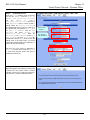
Steps
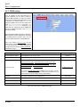
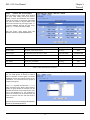
3.4.1 Setup WAN1 IP
Step 1.
Setup WAN1 port
BASIC SETUP > WAN Settings > WAN1 IP > Fixed IP Address
Here we select Fixed IP Address method in
WAN1 port. Fill in the IP Address, Subnet
Mask, Gateway IP. And then enter the other
DNS IP Address, Routing Protocol fields.
Click Apply to finish this setting.
23
Part II
Basic Configuration
IP Address
Assignment
FIELD
PPP over
Ethernet
D-Link
Range / Format
EXAMPLE
Default WAN
link
(Gateway/DNS)
When Default WAN link is enabled. All the
packets sent out from DFL-1500 will be via
this port.
Enable/Disable
Enabled
Get DNS
Automatically /
DNS IP Address
Get DNS Automatically à Get DNS related
information from DHCP Server
DNS IP Address à manually specify these
Primary and Secondary DNS Server
information
Get DNS
Automatically /
DNS IP Address
Get DNS
Automatically
Routing Protocol
Determine to enable the dynamic routing
protocol, to receive RIP message, to send out
the RIP message if the RIP message is received
or not.
None,
RIPv1/In,
RIPv1/In+Out,
RIPv2/In,
RIPv2/In+Out,
OSPF
OSPF Area ID
Specify OSPF area ID number
IPv4 format or
digit string (Max
9 bits)
Default WAN
link
(Gateway/DNS)
When Default WAN link is enabled. All the
packets sent out from DFL-1500 will be via
this port.
Enable/Disable
Enabled
IP Address
Specified IP address
IPv4 format
61.2.1.1
Subnet Mask
Specified subnet mask
IPv4 format
255.255.255.248
Gateway IP
Default gateway IP address
IPv4 format
61.2.1.6
DNS IP Address:
Primary DNS
Secondary DNS
Specified Primary and Secondary DNS Server
address
IPv4 format
Primary DNS:
168.95.1.1
Secondary DNS:
0.0.0.0
Routing Protocol
Determine to enable the dynamic routing
protocol, to receive RIP message, to send out
the RIP message if the RIP message is received
or not.
None,
RIPv1/In,
RIPv1/In+Out,
RIPv2/In,
RIPv2/In+Out,
OSPF
OSPF Area ID
Specify OSPF area ID number
IPv4 format or
digit string (Max
9 bits)
Default WAN
link
(Gateway/DNS)
When Default WAN link is enabled, all the
packets sent out from DFL-1500 will be via
this port.
Enable/Disable
Enabled
Service Name
ISP vendor (Optional)
text string
So-Net
User Name
The user name of PPPoE account
text string
Hey
Password
The password of PPPoE account
text string
G54688
Get IP
Automatically
(DHCP)
Fixed IP Address
DESCRIPTION
24
None
None
DFL-1500 User Manual
Chapter 3
Basic Setup
Get DNS
Automatically /
DNS IP Address
Get DNS Automatically à Get DNS related
information from PPPoE ISP
DNS IP Address à manually specify these
Primary and Secondary DNS Server
information
Get DNS
Automatically /
DNS IP Address
Disconnect
button
Through click Disconnect button to disconnect
PPPoE link
Disconnect
Get DNS
Automatically
Click Disconnect
Table 3-1 Detailed information of setup WAN port configuration
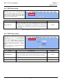
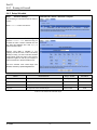
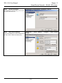
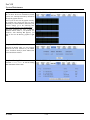
3.4.2 Setup DMZ1, LAN1 Status
Step 1.
Setup DMZ port
BASIC SETUP > DMZ Settings > DMZ1 Status
Here we are going to configure the DMZ1
settings. Setup IP Address and IP Subnet
Mask, and determine if you would like to enable
the DHCP Server. And then select Routing
Protocol. Click Apply to finish this setting.
FIELD
DESCRIPTION
Range / Format
EXAMPLE
IP Address
DMZ port IP address
IPv4 format
IP Subnet Mask
DMZ port IP subnet mask
netmask format
255.255.255.0
Enable DHCP Server
Enable DMZ port of the DHCP Sever or not
Enable/Disable
Enabled
IP Pool Starting Address
Specify the starting address of the DHCP IP address.
IPv4 format in the
DMZ address
range
10.1.1.1
Pool Size(max size: 253)
Specify the numbers of the DHCP IP address.
1 ~253
Primary DNS Server
Specify the Primary DNS Server IP address of the DHCP
information.
IPv4 format
10.1.1.254
Secondary DNS Server
Specify the Secondary DNS Server IP address of the DHCP
information.
IPv4 format
0.0.0.0
Lease time(sec)
Specify DHCP information lease time
greater than 0
7200
Routing Protocol
Determine to enable the dynamic routing protocol (RIP), to
receive RIP message, to send out RIP message if the
message is received or not.
None / RIPv1In /
RIPv1In+out /
RIPv2In /
RIPv2In+out /
OSPF
None
25
10.1.1.254
20
Part II
Basic Configuration
OSPF Area ID
IPv4 format or
digit string (Max
9 bits)
Specify OSPF area ID number
N/A
Table 3-2 Configure DMZ network settings
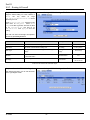
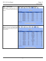
Step 2.
BASIC SETUP > LAN Settings > LAN1 Status
Setup LAN port
Here we are going to configure the LAN1 settings.
Setup IP Address and IP Subnet Mask, and
determine if you would like to enable the DHCP
Server. And then select Routing Protocol. Click
Apply to finish this setting.
FIELD
DESCRIPTION
Range / Format
EXAMPLE
IP Address
LAN1 port IP address
IPv4 format
IP Subnet Mask
LAN1 port IP subnet mask
netmask format
255.255.255.0
Enable DHCP Server
Enable LAN1 port of the DHCP Sever or not
Enable/Disable
Enabled
IP Pool Starting Address
Specify the starting address of the DHCP IP address.
IPv4 format in the
LAN1 address
range
Pool Size(max size: 253)
Specify the numbers of the DHCP IP address.
1 ~253
Primary DNS Server
Specify the Primary DNS Server IP address of the DHCP
information.
IPv4 format
192.168.40.254
Secondary DNS Server
Specify the Secondary DNS Server IP address of the DHCP
information.
IPv4 format
0.0.0.0
Lease time(sec)
Specify DHCP information lease time
greater than 0
7200
Routing Protocol
Determine to enable the dynamic routing protocol (RIP), to
receive RIP message, to send out RIP message if the
message is received or not.
None / RIPv1In /
RIPv1In+out /
RIPv2In /
RIPv2In+out /
OSPF
None
OSPF Area ID
Specify OSPF area ID number
IPv4 format or
digit string (Max
9 bits)
N/A
Table 3-3 Configure LAN network settings
D-Link
26
192.168.40.254
192.168.40.100
20
DFL-1500 User Manual
Chapter 3
Basic Setup
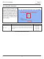
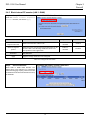
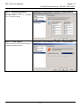
3.4.3 Setup WAN1 IP alias
Step 3.
Add WAN1 IP alias
BASIC SETUP > WAN Settings > IP Alias > Add
Suppose you apply 8 IP addresses from ISP. The
range of the ISP-given IP address is from
61.2.1.0 to 61.2.1.7. Now you would like to add
three WAN1 IP aliases. Select WAN1 in the
Interface field. Enter the IP alias and Netmask
with 61.2.1.2/255.255.255.248. Key in 3 into the
Alias size field. And then click Apply.
Notice:It’s the same way to set IP alias in DMZ or
LAN.
FIELD
DESCRIPTION
Range / Format
EXAMPLE
Interface
The interface which we set for the IP alias
WAN interfaces
WAN1
IP alias
The alias IP address
IPv4 format
61.2.1.2
Netmask
The netmask of the IP alias
netmask format
Alias size
The size of IP alias address
Max 60
255.255.255.248
3
Table 3-4 Add a IP alias record
Step 4.
Edit, Delete IP alias record
BASIC SETUP > WAN Settings > IP Alias
You can easily add, edit, or delete IP alias
records by the Add, Edit, or Delete button.
FIELD
DESCRIPTION
EXAMPLE
Prev. Page
If there are more than one IP alias pages, you can press Prev. Page to
back to the previous page.
N/A
Add
Insert a new IP alias record.
N/A
Edit
Edit the properties of the existent record.
N/A
Delete
Delete the indicated record.
N/A
27
Part II
Basic Configuration
Next Page
If there are more than one action records, you can press Next Page to go
to the next page.
N/A
Table 3-5 Show the entered IP alias records
Maximize IP alias records
of DFL-1500
WAN port
60 records
DMZ port
10 records
LAN port
10 records
Table 3-6 IP alias limitation of each port
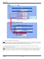
Step 5.
See the IP alias setting in the
“WAN1 IP” page
After entering the IP alias address, it will
show the result in the “WAN1 IP” page.
BASIC SETUP > WAN Settings > WAN1 IP > Fixed IP Address
Warning: If you select Fixed IP Address as
your WAN link type and set any IP alias, the
previous set IP aliases will disappear when you
try to exchange the WAN link type to other type
such as DHCP or PPPoE.
D-Link
28
DFL-1500 User Manual
Chapter 4
System Tools
Chapter 4
System Tools
This chapter introduces System Management and explains how to implement it.
4.1
1.
2.
3.
4.
5.
6.
4.2
1.
2.
3.
4.
5.
6.
4.3
1.
2.
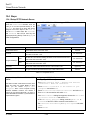
Demand
Basic configurations for domain name, password, system time, timeout and services.
DDNS: Suppose the DFL-1500’s WAN uses dynamic IP but needs a fixed host name. When the IP is changed, it is
necessary to have the DNS record updated accordingly. To use this service, one has to register the account, password, and
the wanted host name with the service provider.
DNS Proxy: Shorten the time of DNS lookup performed by applications.
DHCP Relay: It is to solve the problem that when the DHCP client is not in the same domain with the DHCP server, the
DHCP broadcast will not be received by the server. If the client is in the LAN (192.168.40.X) while the server is located in
the DMZ (10.1.1.4), the server will not receive any broadcast packet from the client.
The System Administrator would like to monitor the device from remote side efficiently.
Suppose our company applies three ISPs, but there are just two default WAN ports in the DFL-1500. You hope to connect
the whole ISP links to the DFL-1500.
Objectives
Configure the general properties, such as domain name, password, system time, and connection timeout correctly. Besides,
we can configure the prefered service name as the service name/numeric mapping list.
DDNS: By using the DDNS (Dynamic DNS), the DFL-1500 will send the request for modification of the corresponding
DNS record to the DDNS server after the IP is changed.
DNS Proxy: Reduce the number of DNS requests and the time for DNS lookup.
DHCP Relay: Enable the DHCP client to contact with the DHCP server located in different domain and get the required IP.
Through the SNMP manager, we can easily monitor the device status.
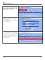
We hope to customize the interface of DFL-1500 to fit our requests.
Methods
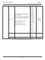
Configure the domain name, password, system time, connection timeout and service name.
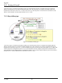
DDNS: Configure the DFL-1500 so that whenever the IP of the DFL-1500 is changed, it will send requests to the DDNS
server to refresh the DNS record. As the following Figure 4-1 demonstrated, the original DFL-1 has registered WAN1 IP
address “61.2.1.1” on the DDNS server (www.dyndns.org). It’s domain name address is “me.dyndns.org”. If the WAN1 IP
address is reassigned by the ISP, DFL-1 will update the registered IP address “61.2.1.1” as the assigned one. This is the
base mechanism of the DDNS.
29
Part II
Basic Configuration
Figure 4-1 DDNS mechanism chart
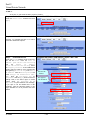
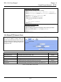
3.
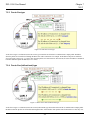
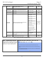
DNS Proxy: After activating the DNS proxy mode, the client can set its DNS server to the DFL-1500 (that is, send the
DNS requests to the DFL-1500). The DFL-1500 will then make the enquiry to the DNS server and return the result to the
client. Besides, the caching mechanism performed by the DNS proxy can also help reduce possible duplicate DNS lookups.
As the following Figure 4-2 described. DFL-1 redirects the DNS request from PC1_1 to the real DNS server (140.113.1.1).
Figure 4-2 DNS Proxy mechanism chart
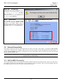
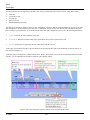
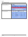
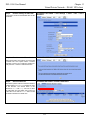
4.
DHCP Relay: Activate the DHCP relay mode of DFL-1500 so that the DFL-1500 will become the relay agent and relay the
DHCP broadcast to the configured DHCP server. As the following Figure 4-3 described, DFL-1 redirects the DHCP
D-Link
30
DFL-1500 User Manual
Chapter 4
System Tools
request from the preconfigured port (LAN1) to the real DHCP server (10.1.1.4). Besides, in this diagram, we can find that
the PC of DMZ region communicated with the DHCP server directly.
Figure 4-3 DHCP Relay mechanism chart
5.
As the following Figure 4-4 demonstrated, there is an embedded snmp agent in the DFL-1500. So you can use SNMP
manager to monitor the DFL-1500 system status, network status ,etc. from either LAN or internet.
31
Part II
Basic Configuration
Figure 4-4 It is efficient to use SNMP Manager to monitor DFL-1500 device
6.
We can adjust the DFL-1500 interface in the SYSTEM TOOLS > Admin Settings > Interface in according to our
preference and requirement (3 WAN, 1 DMZ, 1 LAN). As the following Figure 4-5 demonstrated, there are three ISP
connected onto DFL-1500. So we must adjust the interface up to 3 WAN ports to fit the current condition.
Figure 4-5 Adjust DFL-1500 interface to fit present situation
D-Link
32
DFL-1500 User Manual
4.4
Chapter 4
System Tools
Steps
4.4.1 General settings
Step 1.
SYSTEM TOOLS > Admin Settings > General
General Setup
Enter the Host Name as DFL-1, Domain Name
as the domain name of your company Click
Apply.
FIELD
DESCRIPTION
Host Name
The host name of the DFL-1500 device
Domain Name
Fill in the domain name of company
EXAMPLE
DFL-1
dlink.com
Table 4-1 System Tools - General Setup menu
Step 2.
Change Password
SYSTEM TOOLS > Admin Settings > Password
Enter the current password in the Old Password
field. Enter the new password in the New
Password and retype it in the Confirm
Password field. Click Apply.
FIELD
DESCRIPTION
EXAMPLE
Old Password
The original password of administrator
admin
New Password
The new selected password
12345
Confirm Password
Double confirm the new selected password
12345
Table 4-2 Enter new password
33
Part II
Basic Configuration
Step 3.
Setup Time/Date
SYSTEM TOOLS > Admin Settings > Time/Date
Select the Time Zone where you are located.
Enter the nearest NTP time server in the NTP
time server address. Note that your DNS
must be set if the entered address requires
domain name lookup. You can also enter an IP
address instead. Check the Continuously
(every 3 min) update system clock and
click Apply. The DFL-1500 will immediately
update the system time and will periodically
update it. Check the Update system clock
using the time server at boot time and
click Apply if you want to update the clock at
each boot. If you want to manually change the
system time, uncheck the Continuously
(every 3 min) update system clock and
proceed by entering the target date.
FIELD
DESCRIPTION
EXAMPLE
Time zone
the time zone of your area
N/A
NTP time server address
Use NTP time server to auto update date/time value
Continuously (every 3 min)
update system clock
System will update system date/time value every 3 minutes to NTP time
sever.
Enabled
Update system clock using
the time server at boot time
System will update system date/time value to the NTP time server at boot
time.
disabled
Manual Time Setup
Manual setting Time & Date value.
tock.usno.navy.mil
N/A
Table 4-3 System Tools – Time Data menu
Step 4.
Setup Timeout
SYSTEM TOOLS > Admin Settings > Timeout
Select the target timeout (e.g. 10 min) from the
System Auto Timeout Lifetime. Click the
Apply button. Now the browser will not timeout
for the following 10 minutes after your last
touching of it.
FIELD
System Auto Timeout
Lifetime
DESCRIPTION
When system is idle for a specified time, system will force the people
who logins into the system will logout automatically.
Table 4-4 System Tools – Timeout menu
D-Link
34
EXAMPLE
10
DFL-1500 User Manual
Step 5.
Chapter 4
System Tools
SYSTEM TOOLS > Admin Settings > Services
Configure Services
We can configure the service name and numeric
port number as the same group, so you can
simply use the domain name for the configuration
in the DFL-1500. If you want to add/edit/delete
the service record, just click the below button to
add/edit/delete it.
Remember that when you add a service, it will be
sorted by the port number. And also the service
name is top-down matched by the port number
when the logs record the service in the firewall
logs page.
BUTTON
DESCRIPTION
Add
Add a service name record
Edit
Edit an existing service name record
Delete
Delete an existing service name record
Table 4-5 Setup the service name record
35
Part II
Basic Configuration
4.4.2 DDNS setting
Step 1.
Setup DDNS
SYSTEM TOOLS > Admin Settings > DDNS
If the IP address of DFL-1500 WAN port is
dynamic allocated, you may want to have the
Dynamic DNS mechanism to make your partner
always use the same domain name (like xxx.com)
to connect to you. Select a WAN interface to
update the DDNS record. Here we supply three
DDNS Service Providers. Fill in the Host
Name, Username, Password supplied by the
DDNS web site. Please refer to the DDNS web
site for the detailed information. Click Apply to
activate the settings.
Before setting the DDNS information in this page.
Make sure that you have registered an account in
the indicated Service Provider. Then you can
enter the related information in the DDNS page.
Note: If you choose “WWW.ORAY.NET” as your
DDNS service provider, a default port number
5050 will show in the Port field. It means that if
you use this port to connect to WWW.ORAY.NET,
it will be free charge.
FIELD
DESCRIPTION
EXAMPLE
Enable DDNS for WAN1
Enable DDNS feature of DFL-1500
Enabled
Interface
Assign which public IP address of interface to the DDNS server.
WAN1
Service Provider
The domain address of DDNS server. In the DFL-1500, we provide
WWW.DYNDNS.ORG, WWW.DHS.ORG, WWW.ORAY.NET,
WWW.CHANGEIP.COM, WWW.ADSLDNS.NET,
WWW.NO-IP.COM, WWW.DNS2GO.COM, WWW.3322.ORG,
WWW.88IP.NET, and WWW.HN.ORG ten websites for choice.
WWW.ORAY.NET
If you choose WWW.ORAY.NET as DDNS service provider, it would
register the source IP address which is connected to the DDNS server. It
means that the WAN1 IP address must be public address.
Hostname
The registered Hostname in the DDNS server.
abc.vicp.net
Username
The registered username in the DDNS server.
john
Password
The registered password in the DDNS server.
123456
Port
The default port number to connect to WWW.ORAY.NET for free charge
Table 4-6 System Tools – DDNS setting page
D-Link
36
5050
DFL-1500 User Manual
Chapter 4
System Tools
4.4.3 DNS Proxy setting
Step 1.
SYSTEM TOOLS > Admin Settings > DNS Proxy
Setup DNS Proxy
Check the Enable DNS Proxy and click the
Apply to store the settings. From now on, your
LAN/DMZ PCs can use DFL-1500 as their DNS
server, as long as the DNS server for DFL-1500
has been set in its WAN settings.
FIELD
Enable DNS Proxy
DESCRIPTION
EXAMPLE
When the host which resides at the LAN/DMZ region sends a DNS
Request to the DNS server (DFL-1500). DFL-1500 will request for
forwarding it to the assigned DNS server. When there is a response from
assigned DNS server, then DFL-1500 will forward it back to the host of
the LAN/DMZ.
Enabled
Table 4-7 System Tools – DNS Proxy menu
4.4.4 DHCP Relay setting
Step 1.
Setup DHCP Relay
SYSTEM TOOLS > Admin Settings > DHCP Relay
Check the Enable DHCP Relay. Enter the IP
address of your DHCP server. Here we enter the
DHCP Server address 10.1.1.4. Check the
relay domain of DFL-1500 that needs to be
relayed. Namely, check the one where the DHCP
clients are located. And click the Apply button
finally.
Notice, the DHCP Server can not be located with
the subnet range of Relay Domain.
FIELD
DESCRIPTION
EXAMPLE
Enable DHCP Relay
When the host of the LAN/DMZ in the DFL-1500 internal network sends
a DHCP request, DFL-1500 will forward it automatically to the specified
DHCP server (different subnet from the network segment of the DHCP
client).
Enabled
DHCP Server
Current location of the DHCP server.
10.1.1.4
Relay Domain
The locations of the DHCP clients.
Table 4-8 System Tools – DHCP Relay menu
37
Enable LAN1
Part II
Basic Configuration
4.4.5 SNMP Control
Step 1.
Setup SNMP Control
SYSTEM TOOLS > SNMP Control
Through setting the related information in this
page, we can use SNMP manager to monitor the
system status, network status of DFL-1500.
FIELD
DESCRIPTION
EXAMPLE
Enable SNMP
Enable the SNMP function or not.
System Name
The device name of DFL-1500.
System Location
The settled location of DFL-1500.
Contact Info
The person who takes charge of the DFL-1500.
Get community
The community which can get the SNMP information. Here
“community” is something like password.
public-ro
Set community
The community which can get the SNMP information. Here
“community” is something like password.
private-rw
Trusted hosts
The IP address which can get or set community from the DFL-1500.
192.168.1.5
Trap community
The community which will send SNMP trap. Here “community” is
something like password.
trap-comm
Trap destination
The IP address which will send SNMP trap from the DFL-1500.
192.168.1.5
D-Link
Enabled
DFL-1.dlink.com
Office
38
mis
DFL-1500 User Manual
Chapter 4
System Tools
4.4.6 Change DFL-1500 interface
Step 1.
Change Interface definition
SYSTEM TOOLS > Admin Settings > Interface
The default port settings are 2 WAN ports, 1 DMZ
port and 2 LAN ports. But in order to fit our
requirement. Here we select 3 WAN (port1~3), 1
DMZ (port4), 1 LAN (port5). And then press apply
button to reboot DFL-1500. Note that the DMZ
and LAN port IP addresses are going to be
10.1.1.254 and 192.168.1.254 after device
finishes reboot. Besides, there should be at least
one WAN port and one LAN port existing in the
DFL-1500. You are not allowed to casually
change the interface to the state which has no
LAN port or WAN port.
FIELD
Port1 ~ Port5
DESCRIPTION
EXAMPLE
You can specify WAN / LAN / DMZ for each port by your preference.
However, there must be one WAN and one LAN interface existing in the
DFL-1500.
Port1 : WAN
Port2 : WAN
Port3 : WAN
Port4 : DMZ
Port5 : LAN
Table 4-9 Change the DFL-1500 interface setting
39
DFL-1500 User Manual
Chapter 5
Remote Management
Chapter 5
Remote Management
This chapter introduces remote management and explains how to implement it.
5.1
Demands
Administrators may want to manage the DFL-1500 remotely from any PC in LAN_1 with HTTP at port 8080, and from WAN_PC
with TELNET. In addition, the DFL-1500 may be more secure if monitored by a trusted host (PC1_1). What is more, the DFL-1500
should not respond to ping to hide itself. The remote management function in DFL-1500 devices is implemented by hidden Firewall
rules.
5.2
1.
2.
3.
4.
Methods
Only allow management by WAN_PC (140.2.5.1) at the WAN1 side.
Administrators can use browsers to connect to http://192.168.40.254:8080 for management.
Allow SNMP monitoring by PC1_1 (192.168.40.1) at the LAN1 side.
Do not respond to ICMP ECHO packets at the WAN1 side.
Figure 5-1 Some management methods of DFL-1500
41
Part II
Basic Configuration
5.3
Steps
5.3.1 Telnet
Step 2.
Setup Telnet
Enter 23 instead of the default 2323 in the
Server Port field. Check the WAN1 checkbox.
Click the Selected of Secure Client IP
Address, and then enter the specified IP
address
(140.2.5.1)
for
accessing
DFL-1500. And click the Apply.
SYSTEM TOOLS > Remote Mgt. > TELNET
5.3.2 WWW
Step 1.
Setup WWW
SYSTEM TOOLS > Remote Mgt. > WWW
Check the LAN1 checkbox, and enter the new
Server Port 8080 that will be accessed by the
user’s browser (http://192.168.40.254:8080).
Here we click All for all no IP range limitation of
clients. And click the Apply button.
Note that the Secure Client IP Address is the
IP address which can be used to configure
DFL-1500.
Step 2.
Warming message
If you click the Selected of Secure Client IP
Address and then enter the specified IP
address, a warning message will appear to notice
you that “Warming! If you are connecting
to this Firewall with HTTP, this action
may disconnect your session. Please
remember the settings and reconnect to
the firewall again.” after applying the
settings.
5.3.3 SNMP
Step 1.
Setup SNMP
SYSTEM TOOLS > Remote Mgt. > SNMP
Check the LAN1 checkbox. In the Secure
Client Address field. If you prefer indicated
specified IP address. Just click the Selected,
and enter the valid IP address for reading the
SNMP MIBs at the DFL-1500. Finally click the
Apply button.
D-Link
42
DFL-1500 User Manual
Chapter 5
Remote Management
5.3.4 ICMP
Step 1.
Setup ICMP
SYSTEM TOOLS > Remote Mgt. > MISC
Uncheck the WAN1 checkbox and make others
checked. Then click the Apply button.
43
Part II
Basic Configuration
Chapter 6
Authentication
This chapter introduces user authentication and explains how to implement it.
6.1
Demands
DFL-1500 VPN/Firewall Router support user authentication to the DFL-1500 user database, to a RADIUS server or to a LDAP
server. You can add username and password to allow the user to authenticate using the internal database or connect to the internet.
You can also add the name of a Radius server and select Radius to allow the user to authenticate using the selected Radius server.
6.2
Methods
Remember that you can only use web browser to do the authentication in order for you to pass through the DFL-1500. If you cannot
pass the authentication, you can access neither external internet nor internal resouces. By default, servers under DMZ interface can
access internet without the authentication. PCs under both LAN1 and LAN2 interface has to pass the authentication first and then
they can access the internet or internal resouces under other interfaces (LAN1/LAN2 or DMZ). If a PC under LAN1 or LAN2
inteface will access internet or internal resources without the authentication, you can add this PC’s IP address into the Exempt Host
list.
There are fore steps to configure the authentication:
1. Setting authentication timeout.
2. Configuring the Authentication Type.
3. Configuring the Authentication Setting.
4. Configuring the Exempt Host.
6.3
Steps
6.3.1 Local Setting
Step 1.
Enable Authentication
Basic Setup > Authentication > Authentication
Check the Enable Authentication checkbox.
Set Auth timeout to control how long
authenticated firewall connections are valid. The
default authentication timeout is 30 minutes.
Select the Authentication Type.
D-Link
44
DFL-1500 User Manual
Step 2.
Configure Local Settings
Chapter 6
Authentication
Basic Setup > Authentication > Authentication > Local
Enter the Username and Password, and then
click Add to add it to user’s list. If you would like to
delete a user, just click that username and then
click Delete to remove it. Click Apply to finish the
settings.
Step 3.
Show the Authentication
After applying Local setting, there will be an
Authentication dialog to ask you to enter the
Username and Password when you would like
to connect to the internet. And then click Login.
Step 4.
Show the time left
When you pass the authentication, a message
box will appear to tell you how long the
connection will remain.
45
Part II
Basic Configuration
6.3.2 PoP3(s) Setting
Step 1.
Configure Pop3(s) Settings
Basic Setup > Authentication > Authentication > Pop3(s)
Enter Server IP and Server Port. Check the
Encryption as SSL. Click Apply to store the
settings.
6.3.3 Imap(s) Setting
Step 1.
Configure Imap(s) Settings
Basic Setup > Authentication > Authentication > Imap(s)
Enter Server IP and Server Port. Check the
Encryption as SSL. Click Apply to store the
settings.
6.3.4 Radius Setting
Step 1.
Configure Radius Settings
Basic Setup > Authentication > Authentication > Radius
If you have configured RADIUS support and a
user is required to authenticate using a RADIUS
server, the DFL-1500 then will contact the
RADIUS server for authentication.
Enter Server IP/Server Port and enter the
RADIUS Server Secret. Click Apply to store
the settings.
D-Link
46
DFL-1500 User Manual
Chapter 6
Authentication
6.3.5 LDAP Setting
Step 1.
Configure LDAP Settings
Basic Setup > Authentication > Authentication > LDAP
If you have configured LDAP support and a user
is required to authenticate using a LDAP server,
the DFL-1500 will then contact the LDAP server
for authentication. To authentication with the
DFL-1500, the user enters a user name and
password. The DFL-1500 sends this user name
and password to the LDAP server. If the LDAP
server can authenticate the user, the user is
successfully authenticated with the DFL-1500.
Enter LDAP Server IP and then enter the
distinguished name (Base DN) used to look up
entries on the LDAP server. For example, you
can use the Base DN like ou=accouts,
dc=dlink,dc=com, where ou is organization
unit and dc is domain component. Enter the
common name identifier as UID (it may be named
as cn) for the LDAP server.
6.3.6 Exempt Host
Step 2.
Configuring the Exempt Host
Basic Setup > Authentication > Exempt Host
Enter the exempt host IP Address, and click
Add to add an IP address. When enabling
authentication, the exempt IP address list will
pass the authentication.
47
Part III
NAT、Routing & Firewall
Part III
NAT、Routing & Firewall
D-Link
48
DFL-1500 User Manual
Chapter 7
NAT
Chapter 7
NAT
This chapter introduces NAT and explains how to implement it in DFL-1500.
To facilitate the explanation on how DFL-1500 implements NAT and how to use it, we zoom in the left part of Figure 1-7
into Figure 7-1.
7.1
1.
Demands
The number of public IP address allocated to each Internet subscribers is often very limited compared to the number of PCs
in the LAN1. Additionally, public-IP hosts are directly exposed to the Internet and have more chances to be cracked by
intruders. As the Figure 7-1 illustrated, you hope all the pcs located at LAN1 and DMZ1 can connect internet through
limited IP address (61.2.1.1).
Figure 7-1 All the internal PCs can connect internet through limited WAN IP address by using NAT technology
2.
Internet servers provided by your company may open many ports in default that may be dangerous if exposed to the public
Internet. As the Figure 7-2 illustrated, we make the real servers hide behind the DFL-1500. And all the internet clients can
still access the service of servers.
49
Part III
NAT、Routing & Firewall
Figure 7-2 Internet clients can access the server behind the DFL-1500
7.2
1.
2.
7.3
1.
2.
Objectives
Let PC1_1~PC1_5 connect to the Internet.
As the Figure 7-2 illustrated, the clients will connect to the DFL-1500. Then DFL-1500 will forward the packet to the real
server. So FTPServer1 (10.1.1.5) will be accessed by other Internet users.
Methods
Assign private IP addresses to the PC1_1~PC1_5. Setup NAT at DFL-1500 to map those assigned private hosts under
LAN1 to the public IP address WAN_IP at the WAN1 side.
Assign a private IP address to the FTPServer1. Setup Virtual Server at DFL-1500 to redirect “any connections towards
some port of WAN1” to the port 21 at the FTPServer1.
D-Link
50
DFL-1500 User Manual
Chapter 7
NAT
Figure 7-3 DFL-1500 plays the role as Virtual Server
As the above Figure 7-3 illustrates, the server 10.1.1.5 provides FTP service. But it is located on the DMZ region behind
DFL-1500. And DFL-1500 will act as a Virtual Server role which redirects the packets to the real server 10.1.1.5. And you
can announce to the internet users that there exists a ftp server IP/port is 61.2.1.1/44444. So, all the internet users will
just connect the 61.2.1.1/44444 to get ftp service.
7.4
Steps
7.4.1 Setup Many-to-one NAT rules
Step 1.
Enable NAT
ADVANCED SETTINGS > NAT > Status
Select the Basic from the list of Network
Address Translation Mode. Click Apply.
Now the DFL-1500 will automatically set the NAT
rules for LAN/DMZ zones. Namely, all internal
networks can establish connections to the outside
world if the WAN settings are correct.
51
Part III
NAT、Routing & Firewall
FIELD
Network Address
Translation Mode
BUTTON
DESCRIPTION
Range / Format
Determine what NAT type you are using in your network
topology.
Refer more information in the section 7.5.5.
None /
Basic /
Full Feature
DESCRIPTION
Reset NAT Rules
Reset NAT rules to the default status
Reset Server Rules
Clear all the Virtual Server rules.
Clear active NAT/Server
sessions
Clear all the active NAT/Virtual Server sessions.
Apply
Apply the settings which have been configured.
Reset
Clean the filled data and restore the original.
Table 7-1 Determine Network Address Translation Mode
Step 2.
Check NAT Rules
ADVANCED SETTINGS > NAT > NAT Rules
As described in the above, the DFL-1500 has set
the rules for the LAN/DMZ zones. They all belong
to the Many-to-One (M-1) type that will map
many private addresses to the automatically
chosen public IP address. When the WAN
interfaces change the IP, these rules do not
require any manual modifications for the changed
public IP addresses. The rules will reload the new
settings automatically. Besides, you cannot
insert/edit any rules under the Basic mode.
Step 3.
Switch the NAT Mode
ADVANCED SETTINGS > NAT > Status
Select the Full Feature from the list of
Network Address Translation Mode. Click
Apply. After applying the setting, the page will
highlight a warning saying that the rules are no
more automatically maintained by the DFL-1500.
If you change the LAN/DMZ IP settings, you have
to manually update related rules by yourself.
Otherwise, hosts in your LAN/DMZ cannot
establish connections to the hosts in the WAN
side.
D-Link
52
EXAMPLE
Basic
DFL-1500 User Manual
Step 4.
Chapter 7
NAT
ADVANCED SETTINGS > NAT > NAT Rules
Customize NAT Rules
In the full-feature mode, the rules can be further
customized. Incoming packets from LAN/DMZ
zones are top-down matched by the NAT rules.
Namely, NAT implements first match. Select the
rule item that you want to do with: insert a new
rule before it; delete it; move it before the
list-box chosen item.
Step 5.
Insert NAT Rule
Step 5.a —
Rule
Insert an Many-to-One
ADVANCED SETTINGS > NAT > NAT Rules > Insert
As described in the above, Many-to-One NAT is
the default NAT rule type in the Basic mode. If
you have other alias LAN/DMZ subnets, you can
manually add a Many-to-One NAT rule for them.
First select the Type as Many-to-One, check the
Activate this rule, enter a Rule name for
this rule, enter the private-IP subnet (an IP
address with a netmask) to be translated, and
enter the public IP address for being translated
into. You can check the Auto choose IP from
WAN ports. The DFL-1500 will automatically
determine which WAN IP is to be translated into.
FIELD
Status
Condition
DESCRIPTION
Range / Format
EXAMPLE
The NAT rule is enabled or not
Enabled /
Disabled
Enabled
Rule name
The NAT rule name
text string
Rule
Source IP /
Netmask
Compared with the incoming packets, whether
Source IP/Netmask is matched or not.
IPv4 format
192.168.40.0 /
255.255.255.0
Type
Determine what NAT method you are using in the
specified NAT rule.
Refer more information in the section 7.5.
Many-to-One /
Many-to-Many /
One-to-One /
One-to-One
(bidirectional)
Many-to-One
Translated Src IP
(Auto choose IP
from WAN ports)
Only work in Many-to-One type, the public IP
address will be assigned by the default wan link.
Enabled /
Disabled
Space / Netmask
When NAT type is not Many-to-One, we must
specify IP address / Netmask directly.
IPv4 format
Activate this rule
Action
Table 7-2 Add a NAT rule
53
Enabled
N/A
Part III
NAT、Routing & Firewall
Step 5.b —
Rule
Insert an Many-to-Many
ADVANCED SETTINGS > NAT > NAT Rules > Insert
If your ISP has assigned a range of public IP to
your company, you can tell DFL-1500 to translate
the private IP addresses into the pool of public IP
addresses. The DFL-1500 will use the first public
IP until DFL-1500 uses up all source ports for the
public IP. DFL-1500 will then choose the second
public IP from the address pool. Select
Many-to-Many from the Type. Enter the subnet
with an IP address and a netmask. Other fields
are the same with those of Many-to-One rules.
However, the DFL-1500 will no longer choose the
device IP for you. It will choose the IP from the
address pool you have entered.
Step 5.c —
Insert an One-to-One Rule
ADVANCED SETTINGS > NAT > NAT Rules > Insert
Though you may have many public IP address for
translation, you may want to make some private
IP to always use a public IP. In this case, you can
select One-to-One from the Type, and enter the
private-public IP address pair in the Source IP
and the Translated Source IP fields.
Step 5.d —
Insert a One-to-One
(Bidirectional) Rule
ADVANCED SETTINGS > NAT > NAT Rules > Insert
The above three modes allow LAN/DMZ-to-WAN
sessions establishment but do not allow
WAN-to-LAN/DMZ sessions. WAN-to-LAN/DMZ
sessions are allowed by Virtual Server rules. You
can make the One-to-One NAT in the above to
incorporate the WAN-to-LAN/DMZ feature by
selecting the One-to-One (Bidirectional)
from the Type. Note that WAN-to-LAN/DMZ traffic
will be blocked by the Firewall in default. You
have to add a Firewall rule to allow such traffic. If
you expect a LAN/DMZ host to be fully accessed
by public Internet users, use this mode. Note that
this mode is extremely dangerous because the
host is fully exposed to the Internet and may be
cracked. Always use Virtual Server rules first.
D-Link
54
DFL-1500 User Manual
Chapter 7
NAT
7.4.2 Setup Virtual Server for the FtpServer1
Step 1.
Device IP Address
BASIC SETUP > DMZ Settings > DMZ1 Status
Setup the IP Address and IP Subnet Mask for
the DFL-1500 of the DMZ1 interface.
Step 2.
Client IP Range
Enable the DHCP server if you want to use
DFL-1500 to assign IP addresses to the
computers under DMZ1. Here we make the
DHCP feature enabled.
Step 3.
Apply the Changes
Click Apply to save your settings.
Step 4.
Check NAT Status
ADVANCED SETTINGS > NAT > Status
The default setting of NAT is in Basic Mode.
After applying the Step 3, the NAT is
automatically configured with the rules to let all
private-IP LAN/DMZ-to-WAN requests to be
translated with the public IP assigned by the ISP.
Step 5.
Check NAT Rules
ADVANCED SETTINGS > NAT > NAT Rules
The DFL-1500 has added the NAT rules
automatically as right diagram described. The
rule Basic-DMZ1 (number 1) means that, when
matching
the
condition
(requests
of
LAN/DMZ-to-WAN direction with its source IP
falling
in
the
range
of
10.1.1.254/255.255.255.0), the request will
be translated into a public-source-IP requests,
and then be forwarded to the destinations.
55
Part III
NAT、Routing & Firewall
Step 6.
Setup IP for the FTP Server
Assign an IP of 10.1.1.1/255.255.255.0 to the
FTP server under DMZ1. Assume the FTP Server
is at 10.1.1.5. And it is listening on the well-known
port (21).
Step 7.
Setup Server Rules
ADVANCED SETTINGS > NAT > Virtual Servers
Insert a virtual server rule by clicking the Insert
button.
Step 8.
Customize the Rule
ADVANCED SETTINGS > NAT > Virtual Servers > Insert
Customize the rule name as the ftpServer. For
any packets with its destination IP equaling to the
WAN1 IP (61.2.1.1) and destination port
equaling to 44444, ask DFL-1500 to translate the
packet’s destination IP/port into 10.1.1.5/21.
Check the Passive FTP client? to maximize
the compatibility of the FTP protocol. This is
useful if you want to provide connectivity to
passive FTP clients. For passive FTP clients, the
server will return them the private IP address and
the port number for them to connect back to do
data transmissions. Since the private IP from
them cannot be routed to our zone, the data
connections would fail. After enabling this feature,
the DFL-1500 will translate the private IP/port into
an IP/port of its own. Thus the problem is
gracefully solved. Click Apply to proceed.
FIELD
Status
Condition
D-Link
DESCRIPTION
Range / Format
EXAMPLE
Activate this rule
The Virtual Server rule is enabled or not
Enabled /
Disabled
Enabled
Rule name
The Virtual Server rule name
text string
ftpServer
Sessions from
Internet
connecting to
Which interface does the connected session come
from?
WAN interfaces
WAN1
External IP
The public IP address of the Virtual Server.
IPv4 format
61.2.1.1
Service
The service which is provided by the real server.
TCP / UDP
TCP
Type
Port is Single or Range
Single / Range
Single
Dest Port
The TCP/UDP port number which is provided by
the real server.
1 ~65534
44444
56
DFL-1500 User Manual
Chapter 7
NAT
Passive FTP
client
If the Passive FTP client is checked, it will
connect to the internal DMZ FTP server of
DFL-1500 when FTP client uses passive mode.
Otherwise, it will not work.
Enabled /
Disabled
Enabled
Redirect to
internal server
under
The subnet which is located the virtual server.
LAN / DMZ
regions
DMZ1
Internal IP
The IP address which is actually transferred to the
internal DMZ
IPv4 format
10.1.1.5
Port
The port number which is actually transferred to
the internal DMZ.
If you filled 0 in this field, it means that the real
connected port is the same as the translated
destination port.
0 ~ 65534
21
Action
Table 7-3 Add a Virtual Server rule
Step 9.
View the Result
ADVANCED SETTINGS > NAT > Virtual Servers
Now any request towards the DFL-1500’s WAN1
IP (61.2.1.1) with port 44444 will be translated
into a request towards 10.1.1.5 with port 21,
and then be forwarded to the 10.1.1.5. The
FTP server listening at port 21 in 10.1.1.5 will
pick up the request.
7.5
NAT modes introduction
7.5.1 Many-to-One type
Figure 7-4 NAT Many-to-One type
57
Part III
NAT、Routing & Firewall
As the above Figure 7-4 illustrated, NAT Many-to-One type means that many local PCs are translated into only one public IP
address when the packets are forwarded out through the DFL-1500. Take Connection1 for example. Its IP address and port are
translated from 192.168.40.1:2933 to 61.2.1.1:2933. In the same way, when the packets of Connection2 are forwarded out, its IP
address is still translated to the same public IP address (61.2.1.1:7896).
7.5.2 Many-to-Many type
Figure 7-5 NAT Many-to-Many type
As the above Figure 7-5 illustrated, NAT Many-to-Many type means that many local PCs are translated into multiple public IP
addresses when the packets are forwarded out through the DFL-1500. Take Connection1 for example. Its IP address and port are
translated from 192.168.40.1:2933 to 61.2.1.1:2933. Until DFL-1500 uses out of all source ports of the public (61.2.1.1), DFL-1500
will then choose the second public IP (such as 61.2.1.2) from the address pool. For example, Connection2 are forwarded out, the
source IP address will be translated into the second public IP address (61.2.1.2) from the public IP address pools. So the translated
IP address (61.2.1.2:7896) is different from Connection1 one (61.2.1.1:2933).
D-Link
58
DFL-1500 User Manual
Chapter 7
NAT
7.5.3 One-to-One type
Figure 7-6 NAT One-to-One type
As the above Figure 7-6 illustrated, NAT One to One type means that each local PC is translated into a unique public IP address
when the packets are forwarded out through the DFL-1500. Take Connection1 for example. Its IP address and port are translated
from 192.168.40.1:2933 to 61.2.1.1:2933. But, when the packets of Connection2 are forwards out, the source IP address is translated
to another dedicated public IP address(61.2.1.2:7896).
7.5.4 One-to-One (bidirectional) type
Figure 7-7 NAT One-to-One (bidirectional) type
As the above Figure 7-7 illustrated, NAT One to One (bidirectional) type means that each local PC is translated into a unique public
IP address when the packets are forwarded out through the DFL-1500. Besides when packets came from internet to LAN, they were
59
Part III
NAT、Routing & Firewall
translated to the same private IP address too. Take Connection1 for example. Its IP address and port are translated from
192.168.40.1:2933 to 61.2.1.1:2933 in both ways. Accordingly, the source IP address and port of the Connection2 are translated
from 192.168.40.100:7896 to 61.2.1.2:7896 in both ways.
7.5.5 NAT modes & types
The following three NAT modes are supported by DFL-1500 now as the following Table 7-4.
NAT mode
Description
None
The DFL-1500 is in routing mode without performing any address translation.
Basic
The DFL-1500 automatically performs Many-to-One NAT for all LAN/DMZ subnets.
Full Feature
The DFL-1500 can be manually configured with Many-to-One, and Many-to-Many, One-to-One, and
bidirectional One-to-One rules to do policy-based NAT.
Table 7-4 NAT modes overview
If you choose Full Feature mode of NAT at Table 7-4, you may need to edit the rule by yourself. Then you must determine the NAT
type in the NAT rule. What meaning does each NAT type represent? How to determine which NAT type is best choice for you. You
can lookup the explanations and suggestions at Table 7-5.
Type
Description
Usage moment
Many-to-One
Map a pool of private IP addresses to a single
public IP address chosen from the WAN ports.
If the public IP addresses of your company is insufficient, and
you prefer to increase the node which can connect to the
internet. You can just choose the Many-to-One type to fit your
request.
Many-to-Many
Map a pool of private IP addresses to a subnet
range of public IP addresses chosen from the
WAN ports. Only when all ports of the first
public IP are used, it will then use the next
public IP address for transferring by all private
IPs.
One-to-One
Map a single private IP address to a single
public IP address chosen from the WAN ports.
This was useful when you have multiple public
IPs in the WAN ports. And you intended to
map each local server to a unique public IP on
the WAN port.
If you wish to specify a unique internal IP address to transfer a
fixed external IP address. You can specify the One-to-One
type.
An internal host is fully mapped to a WAN IP
address. Notice that you must add a firewall
rule to forward WAN to LAN/DMZ traffic.
If you wish to expose the local pc onto the internet, and open
all internet services outside. You can specify the One-to-One
(bidirectional) type. This will make the local pc you specified
fully exposed to the internet. Additionally you must add a
firewall rule to allow WAN to LAN (or DMZ) traffic forward.
Then you can finish the settings. Be careful to use this type, or
it will endanger your network security.
One-to-One
(bidirectional)
If the public IP address of your company is not only one node
(ex. you have applied extra-one ISP). You may use the
Many-to-Many type to make the multiple public addresses
sharing the outbound bandwidth. So your inbound and
outbound traffic will be more flexible.
Table 7-5 The NAT type comparison
D-Link
60
DFL-1500 User Manual
Chapter 8
Routing
Chapter 8
Routing
This chapter introduces how to add static routing and policy routing entries
To facilitate the explanation on how DFL-1500 implements routing and how to use it. We zoom in the left part of Figure
2-1 into Figure 8-1 and increase some devices for description.
8.1
Demands
1.
There is only one local area (192.168.40.0/24) inside the LAN1 port. Now there is a new financial area (192.168.50.0/24)
in the Figure 8-1. The financial area is connected with a router which is inside the LAN1 port of DFL-1500. So we need to
add the configurations for the financial department.
2.
Refer to the Figure 8-1 description. The bandwidth subscribed from ISP1 is insufficient so that some important traffic, say
the traffic from PCs belonging to the General-Manager-Room department (192.168.40.192/255.255.255.192), is blocked
by the other traffic. We hope that the employees of General-Manager-Room can have a dedicated bandwidth to improve
the quality of connecting internet.
Figure 8-1 Add policy routing entry for the General-Manager-Room department
61
Part III
NAT、Routing & Firewall
8.2
Objectives
1.
We need to let DFL-1500 knows how to forward the packets which is bound for financial department (192.168.50.0/24).
2.
The network administrator plans to solve the problem by subscribing the second link (ISP2). He hopes that all the packets
from the General-Manager-Room (192.168.40.192/26) will pass through the ISP2 link instead of the default ISP1 link.
8.3
Methods
1.
Add a static routing entry to direct the packets towards 192.168.50.0/24 through the router (192.168.40.253).
2.
Add a policy routing entry for the packets coming from General-Manager-Room department (192.168.40.192 /
255.255.255.192) through the ISP2 link.
8.4
Steps
8.4.1 Add a static routing entry
Step 1.
Add a static routing rule
Advanced Settings > Routing > Static Route
Click the Add button to the next process.
Step 2.
Fill out the related field
Advanced Settings > Routing > Static Route > Add
Fill in the Destination and the Netmask field
with 192.168.50.0 and 255.255.255.0.
Assign
the
next
hop
Gateway
as
192.168.40.253 (Router IP address). Click
Add to proceed.
FIELD
DESCRIPTION
Type
Determine this static routing entry record is multiple hosts
(Net) or a single host (Host)。
Destination
The destination IP address of this static routing entry record.
D-Link
62
Range / Format
EXAMPLE
Net / Host
Net
IPv4 format
192.168.50.0
DFL-1500 User Manual
Chapter 8
Routing
Netmask
The destination IP Netmask of this static routing entry
record.
IPv4 format
255.255.255.0
Gateway
The default gateway of this static routing entry record.
IPv4 format
192.168.40.253
Table 8-1Add a static routing entry
Step 3.
View the result
Advanced Settings > Routing > Static Route
The static route has been stored. After filling data
completely, view the static routing entries which
have been set.
Step 4.
View the routing table
You can notice there is an extra routing entry in
the routing table. The indicated routing entry as
right diagram is produced by static routing rule.
Device Status > System Status > Routing Table
63
Part III
NAT、Routing & Firewall
8.4.2 Add a policy routing entry
Step 1.
Setup the ISP2 link
We must add an IP alias record to the WAN1
port because a new ISP link has been applied.
So. See section 3.4.3 for the full procedures.
Here we add an IP alias of WAN1 as
210.2.1.1/255.255.255.248.
Basic Setup > WAN Settings > IP Alias
Step 2.
Advanced Settings > Routing > Policy Route
Insert a policy routing entry
Click Insert button to add a policy routing entry.
Step 3.
Fill out the related field
Advanced Settings > Routing > Policy Route > Insert
For the General-Manager-Room department, we
need to set an extra policy routing entry for them.
So in the Status region, make sure the
Activate this rule is enabled, and then fill in
GenlManaRoom in the Rule name field. In the
Condition region, we fill 192.168.40.192 in
Source IP field. Fill 255.255.255.192 in the
Netmask field. In the Action region, fill forward
to WAN1 with next-hop gateway 210.2.1.6. After
setting as above, the packets which match the
condition, they will follow the predefined action to
forward to the next hop.
D-Link
64
DFL-1500 User Manual
FIELD
Chapter 8
Routing
DESCRIPTION
EXAMPLE
Activate this rule
The policy routing rule is enabled or not.
Enabled /
Disabled
Enabled
Rule name
The policy routing rule name.
text string
GenlManaRoo
m
Incoming packets
from
Packets comes from which interface
LAN / DMZ
regions
LAN1
Source IP &
Netmask
Verify if the incoming packets belong to the range
of the Source IP/Netmask in the policy routing
rule.
IPv4 format /
IPv4 format
192.168.40.192 /
255.255.255.192
Dest IP &
Netmask
Verify if the incoming packets belong to the range
of the Dest IP/Netmask in the policy routing rule.
IPv4 format /
IPv4 format
0.0.0.0 / 0.0.0.0
Service
Verify what is the service of this packet?
ANY / TCP /
UDP / ICMP
Any
Configure src.
port? Type Src.
port
If the service is TCP or UDP, we can choose to
configure or not to configure source port.
Enabled /
Disabled
No
Type
If we decide to configure source port, we must
choose the port to be single or range.
Single / Range
N/A
Src. Port
If we select single at above field, we just have to
fill a port in the first blank space. If we select
range at above field, we need to fill the range of
the ports.
1 ~ 65534
N/A
Configure dest.
port? Type Dest.
port
If the service is TCP or UDP, we can choose to
configure or not to configure destination port.
Enabled /
Disabled
No
Type
If we decide to configure destination port, we
must choose the port to be single or range.
Single / Range
N/A
Dest. Port
If we select single at above field, we just have to
fill a port in the first blank space. If we select
range at above field, we need to fill the range of
the ports.
1 ~ 65534
N/A
Forward to
If the packet is matched to this rule, which
interface does this packet sent out to?
WAN interfaces
WAN1
Nexthop gateway
IP
The next gateway IP address of forwarding
interface.
IPv4 format
210.2.1.6
Status
Condition
Range / Format
Action
Table 8-2 Add a policy routing entry
65
Part III
NAT、Routing & Firewall
Step 4.
View the result
Advanced Settings > Routing > Policy Route
After filling data completely, view the policy
routing entries which have been set.
Step 5.
View the routing table
Device Status > System Status > Routing Table
Finally click the “Routing Table” to see all the
current routing table information.
D-Link
66
DFL-1500 User Manual
Chapter 9
Firewall
Chapter 9
Firewall
This chapter introduces firewall and explains how to implement it.
9.1
1.
2.
3.
4.
5.
6.
9.2
1.
2.
Demands
All rules require source and destination addresses. You have to add addresses to the address list for each interface first if
you would like to add an address to a rule between two interfaces. These addresses must be valid addresses for the network
connected to that interface.
Suppose you would like to use services to control the types of communication accepted or denied by the firewall, you can
add any of the predefined services or created services to a rule.
Suppose the MSN cannot be used in your company from Monday to Friday 9:00~12:00, 13:00~17:30, but you can use it
any time after work. The administrator needs to create the schedules to meet the requirement.
Your company would like to protect some servers or users avoid their IP address snatched by others, and control the
computers to let them accepted or denied by the firewall rule. IP/MAC binding protects the DFL-1500 unit and your
network from IP spoofing attacks. IP spoofing attempts to use the IP address of a trusted computer to connect to or through
the DFL-1500 unit from a different computer. The IP address of a computer can easily be changed to a trusted address, but
MAC addresses are added to Ethernet cards at the factory and cannot easily be changed.
Administrators detect that PC1_1 in LAN_1 is doing something that may hurt our company and should instantly block his
traffic towards the Internet.
A DMZ server was attacked by SYN-Flooding attack and requires the DFL-1500 to protect it.
Objectives
Block the traffic from PC1_1 in LAN1 to the Internet in WAN1.
Start the SYN-Flooding protection.
67
Part III
NAT、Routing & Firewall
Figure 9-1 Setting up the firewall rule
9.3
1.
2.
3.
9.4
Methods
Configure the Address/Service/Schedule first.
Add a LAN1-to-WAN1 Firewall rule to block PC1_1.
Start the SYN-Flooding protection by detecting statistical half-open TCP connections.
Steps
9.4.1 Setup Address
Step 1.
Address Settings
BASIC SETUP > Books > Address > Object
Suppose you would like to configure a firewall
rule, you must add addresses to the addresses
list for each interface first.
Click the Objects hyperlink and then select the
Define Objects. Click Insert to add a new
address object.
Step 2.
Insert a new Address object
BASIC SETUP > Books > Address > Object > Insert
Enter the Address name. Select which address
type the address object will be. And then enter the
IP address.
Note that address name should begin with
alphabet, followed by alphabet/digits/dashes.
FIELD
Address name
Address Type
DESCRIPTION
Range / Format
The name of the address object.
text string
The address type of the object.
Subnet/Range/Host
Table 9-1 The field of the Address object
D-Link
68
EXAMPLE
PC1_1
Host
192.168.40.1
DFL-1500 User Manual
Step 3.
See the Address object
settings
Chapter 9
Firewall
BASIC SETUP > Books > Address > Objects
After entering the new Address object, it will show
the result in the “Object” page.
Note: It is the same way to setup address objects
in the other interfaces.
Step 4.
Address Group Settings
BASIC SETUP > Books > Address > Group
You can add, edit, and delete all other addresses
as required. You can also organize related
addresses into address group to simplify rule
creation.
Click the Groups hyperlink. Select WAN1 to define
Address Groups, and then click Insert to
proceed.
Step 5.
Add a address group
BASIC SETUP > Books > Address > Group > Insert
Enter a Group Name to identify the address
group. Select the addresses from the available
address list and click right arrow to add them to
the Members list. To remove addresses from
address group, please select addresses from the
Members list and then click left arrow.
Note that group name should begin with alphabet,
followed by alphabet/digits/dashes. You can add
address groups to any interface. The address
group can only contain addresses from that
interface. Address group cannot have the same
names as individual addresses. If an address
group is included in a rule, it cannot be deleted
unless it is first removed from the firewall rule.
69
Part III
NAT、Routing & Firewall
9.4.2 Setup Service
Step 1.
Service Settings
BASIC SETUP > Books > Service > Objects
The DFL-1500 predefined firewall services are
listed as right diagram. You can add these
services to any firewall rule or you can add a
service if you need to create a firewall rule for a
service that is not in the predefined service list.
Select Insert to add a new service.
D-Link
70
DFL-1500 User Manual
Step 2.
Chapter 9
Firewall
Insert a new service object
BASIC SETUP > Books > Service > Insert
Enter the Service name. Select which protocol
type (TCP, UDP, ICMP) used by this service.
Specify a Source and Destination Port number
range for the service. If this service uses single
port, enter the number in the first blank. If the
service has more than one port range, select add
to specify additional protocols and port range.
Select Apply to add a new service object.
Note that service name should begin with
alphabet, followed by alphabet/digits/dashes.
FIELD
DESCRIPTION
Range / Format
EXAMPLE
Service name
The name of the service object.
text string
Protocol Type
The protocol type of the service object.
TCP/UDP/ICMP
Configure Source Port?
Configure the source port if yes.
Enable/Disable
N/A
Port type
The service port type.
Single/Range
N/A
Port number
The service port number.
text sting
N/A
Configure Destination port
Configure the destination port if any.
Enable/Disable
N/A
Table 9-2 The field of the Service object
Step 3.
Add a service group
BASIC SETUP > Books > Service > Groups > Insert
You can create groups of services to make it
easier to add rules. A service group can contain
predefined services and custom services in any
combination. You cannot add service groups to
another service group.
Click Groups hyperlink, and then click Insert to
add a new service group. Enter a Group Name to
identify the group. Select the services from the
available services list and click right arrow to copy
them to the Members list. If you would like to
remove the services from the members list, just
select the services and then click left arrow to
remove them.
Note that group name should begin with alphabet,
followed by alphabet/digits/dashes.
71
ANY
TCP/UDP/ICMP
Part III
NAT、Routing & Firewall
9.4.3 Setup Schedule
Step 1.
BASIC SETUP > Books > Schedule > Objects
Schedule Settings
Use scheduling to control when rules are active or
inactive.
Select Insert to add a new service.
Step 2.
Insert a new schedule object
BASIC SETUP > Books > Address > Schedule > Insert
Enter the Schedule name. Select the Day you
would like to active or inactive a firewall rule, and
then select the Start/Stop time. Click Apply to
add the schedule object.
Suppose using MSN is forbidden in your
company from 08:30~12:00, 13:00~17:30 during
Monday to Friday, you have to add two schedule
ranges (08:30~12:00 and 13:00~17:30) and then
group them together in order for your company to
make a firewall rule to block the MSN service.
Note that schedule name should begin with
alphabet, followed by alphabet/digits/dashes.
FIELD
DESCRIPTION
Range / Format
EXAMPLE
Schedule name
The name of the schedule object.
text string
Block-MSN1
Day
The days to active or inactive a firewall rule.
Sun ~ Sat
Mon ~ Fri
Start time
The start time of the schedule object.
24-hour format
08:30
Stop time
The stop time of the schedule object.
24-hour format
12:00
Table 9-3 The field of the Schedule object
D-Link
72
DFL-1500 User Manual
Step 3.
Add a Schedule group
Chapter 9
Firewall
BASIC SETUP > Books > Schedule > Groups > Insert
As Step 2 indicated, you have already created
two schedule objects to block the MSN service.
You can group them to make it easier to block the
MSN service while you would like to make a
firewall rule.
Click Groups hyperlink, and then click Insert to
add a new schedule group. Enter a Group Name
to identify the group. Select the schedules from
the available schedules list and click right arrow
to copy them to the Members list. If you would like
to remove the schedules from the members list,
just select the schedules and then click left arrow
to remove them.
Note that group name should begin with alphabet,
followed by alphabet/digits/dashes.
9.4.4 Setup IP/MAC binding
Step 1.
Enable IP/MAC binding
Advanced Settings > IP/MAC Binding > Status
Check the Enable IP/MAC Binding checkbox,
and then click Apply to apply the setting.
Note that the IP/MAC binding locks IP address for
specific MACs. It achieves the purpose by the
following steps:
Step 1. Initialize default action (Pass/Block).
Step 2. Setup each IP/MAC binding with a rule.
Step 3. Setup a wildcard rule to exclude a range
of IP for the DHCP IP range.
Step 2.
Edit a IP/MAC binding rule
Advanced Settings > IP/MAC Binding > Edit Rules
Select LAN1 as the interface to edit the IP/MAC
binding rules. Suppose the default setting for this
interface is Block, click Insert to add a rule.
Note that you have to add an IP/MAC binding rule
as Allow for your computer to pass the firewall
rule before you block the LAN1-ANY direction,
otherwise you will be block by that rule.
73
Part III
NAT、Routing & Firewall
Step 3.
Add a new IP/MAC binding rule
Advanced Setting > IP/MAC binding > Edit Rules > Insert
Suppose default Setting for LAN1 interface is
Block,
and
only
DHCP
IP
range
192.168.40.101 to 192.168.40.120 will be
allowed by this rule.
Check Activate this rule checkbox. Enter
Rule name as LAN1_DHCP.
Select Allow
Range in the Rule Type field, and enter the Start
IP as 192.168.40.101 and End IP as
192.168.40.120. Click Apply to store this
setting.
Note that rule name should begin with alphabet,
followed by alphabet/digits/dashes.
FIELD
DESCRIPTION
Range / Format
EXAMPLE
Activate this rule
Activate the IP/MAC binding rule.
Enabled/Disabled
Rule name
The name of the IP/MAC binding rule.
text string
LAN1_DHCP
Rule Type
The type of the IP/MAC binding rule is binding or IP
Range..
Binding/Allow
Range
Allow Range
IP/MAC
The IP/MAC address. It should be 12 characters, such
as 0001029140EC.
000000000000
N/A
IP Range
The IP range of the DHCP server.
IPv4 format
Table 9-4 The field of the Schedule object
Step 4.
Show the IP/MAC binding rule
Advanced Setting > IP/MAC binding > Show Rules
After finishing the setting, you can view the result
as the right diagram shown.
D-Link
74
Enabled
192.168.40.101 ~
192.168.40.120
DFL-1500 User Manual
Chapter 9
Firewall
9.4.5 Block internal PC session (LAN à WAN)
Step 1.
Setup NAT
ADVANCED SETTINGS > Firewall > Status
Check the Enable Stateful Inspection
Firewall checkbox, and click the Apply.
FIELD
DESCRIPTION
Range / Format
EXAMPLE
Enable Stateful
Inspection Firewall
Enable Firewall feature of DFL-1500
Enabled /
Disabled
Enabled
Block all fragment
packets
Enable this feature will block the fragmented packets by the
firewall of DFL-1500. Warning: Enable this feature will
cause problem in some applications.
Enabled /
Disabled
Disabled
BUTTON
Apply
DESCRIPTION
Apply the settings which have been configured.
Table 9-5 Configure Firewall status
Step 2.
Add a Firewall Rule
ADVANCED SETTINGS > Firewall > Edit Rules
Select LAN1 to WAN1 traffic direction. The
default action of this direction is to forward all
traffic without logging anything. Click Insert to add
a Firewall block rule before the default rule to stop
the bad traffic.
75
Part III
NAT、Routing & Firewall
Step 3.
Customize the rule
ADVANCED SETTINGS > Firewall > Edit Rules > Insert
Before adding a new firewall, you have to set the
Books
in
the
Basic
>
Books
>
Addresses/Services/Schedules first.
After
configuring the settings, you can then add a new
firewall rule.
Enter the rule name as PC1_1, and select
Schedule. Select Source IP as PC1_1
(192.168.40.1 / 255.255.255.255), and
select Dest. IP as WAN1_ALL. Select Service
as ANY (TCP, UDP and ICMP). Select Block and
Log to the matched session. And choose the
Forward bandwidth class or Reverse
bandwidth class if any. Click the Apply to
apply the changes.
Note that rule name should begin with alphabet,
followed by alphabet/digits/dashes.
FIELD
Status
Condition
Action
DESCRIPTION
EXAMPLE
Enabled / Disabled
Enabled
text string
PC1_1
Activate this rule
Enable the firewall rule for later using
Rule name
The name of the Firewall rule
Source IP
Compared with the incoming packets, whether
Source IP is matched or not.
IPv4 format / IPv4
format
PC1_1
(192.168.40.1
255.255.255.255)
Dest IP
Compared with the incoming packets, whether
Dest IP is matched or not.
IPv4 format / IPv4
format
WAN1_ALL
(0.0.0.0
0.0.0.0)
Service
Verified the service of incoming packet is
belong to each TCP、UDP、ICMP.
ANY
(TCP/UDP/ICMP)
ANY
Forward / Block
the matched
session
If packet is matched the rule condition,
Forward or Block this matched packet?
Forward / Block
Block
do not log / log
the matched
session
If packet is matched the rule condition, Log or
Don’t log this matched packet?
log / do not log
log
Forward
bandwidth class
Forward the bandwidth class if any.
def_class
def_class
Reverse
bandwidth class
Reverse the bandwidth class if any.
def_class
def_class
Table 9-6 Insert a Firewall rule
D-Link
Range / Format
76
DFL-1500 User Manual
Chapter 9
Firewall
Step 4.
View the Firewall Log
You can go to DEVICE Status>Firewall Logs
>Firewall Logs to view the firewall logs. If you
prefer to download these logs, please click the
“Download To Local” button to save the logs to
localhost.
DEVICE Status > Firewall Logs > Firewall Logs
FIELD
No
DESCRIPTION
The indicated firewall log sequence number.
Time
The record time of indicated firewall log.
From
The source IP address (include port) which the indicated log event come from.
To
Protocol/(Service)
Direction
Action
Rule
The destination IP address (include port) for the indicated log event bound.
The record log is TCP, UDP or ICMP / (which service it will be).
The firewall log direction is OUT or IN. The direction is based on the DFL-1500. For example,
“OUT” means the packet is forwarded out to the internet. “IN” means the packet is forwarded into
intranet.
The status of indicated firewall log is Block or Forward.
The log is produced by which firewall rule.
“Default” means the default rule of the selected firewall direction.
“RM XXX” means the log is produced by remote management function (Almost it is the illegal
user who wants to use the Non-Opened remote management functions.
Other condition, it will be marked at the rule number (ex. Rule0, Rule1…).
Table 9-7 Firewall log field description
77
Part III
NAT、Routing & Firewall
9.4.6 Setup Alert detected attack
Step 1.
Setup Attack Alert
ADVANCED SETTINGS > Firewall > Attack Alert
With the Firewall enabled, the DFL-1500 is
already equipped with an Anti-DoS engine within
it. Normal DoS attacks will show up in the log
when detecting and blocking such traffic.
However, Flooding attacks require extra
parameters to recognize. Check the Enable
Alert when attack detected checkbox.
Enter 100 in the One Minute High means that
DFL-1500 starts to generate alerts and delete the
half-open states if 100 half-open states are
established in the last minute. Enter 100 in the
Maximum Incomplete High means that
DFL-1500 starts to generate alerts and delete
half-open states if the current number of
half-open states reaches 100. Enter 10 in the
TCP Maximum Incomplete means that
DFL-1500 starts to generate alerts and delete
half-open states if the number of half-open states
towards a server (SYN-Flooding attack) reaches
10. Check the Blocking time if you want to
stop the traffic towards the server. During this
blocking time, the server can digest the loading.
FIELD
Enable Alert when attack detected
DESCRIPTION
Enable the firewall alert to detect Denial of Service (DoS)
attack.
EXAMPLE
Enabled
Denial of Service Thresholds
One Minute High
This is the rate of new half –open sessions that causes the
firewall to start deleting half open sessions. When the rate of
new connection attempts rises above this number, the DFL-1500
deletes half-open sessions as required to accommodate new
connection attempts.
100
Maximum Incomplete High
This is the number of existing half-open sessions that causes the
firewall to start deleting half-open sessions. When the number of
existing half-open sessions rises above this number, the
DFL-1500 deletes half-open sessions as required to
accommodate new connection requests.
100
TCP Maximum Incomplete
This is the number of existing half-open TCP sessions with the
same destination host IP address that causes the firewall to start
dropping half-open sessions to the same destination host IP
address. Enter a number between 1 and 999. As a general rule,
you should choose a smaller number for a smaller network, a
slower system or limited bandwidth.
10
D-Link
78
DFL-1500 User Manual
Chapter 9
Firewall
Blocking Time
When TCP Maximum Incomplete is reached you can choose if
the next session should be allowed or blocked. If you check
Blocking Time any new sessions will be blocked for the length
of time you specified in the next field (min) and all old
incomplete sessions will be cleared during this period. If you
want strong security, it is better to block the traffic for a short
time, as will give the server some time to digest the loading.
(min)
Enter the length of Blocking Time in minutes.
Table 9-8 Setup the Denial of Service Thresholds of attack alert
79
disabled
0
Part IV
Virtual Private Network
Part IV
Virtual Private Network
D-Link
80
DFL-1500 User Manual
Chapter 10
VPN Technical Introduction
Chapter 10
VPN Technical Introduction
This chapter introduces VPN related technology
10.1 VPN benefit
If you choose to implement VPN technology in your enterprise, then it may bring the following benefits to your company.
1.
Authentication
Ensure the data received is the same as the data that was sent and that the claimed sender is in fact the actual sender.
2.
Integrity
Ensure that data is transmitted from source to destination without undetected alteration.
3.
Confidentiality
Guarantee the intended recipients know what was being sent but unintended parties cannot determine what was sent. This is almost
provided by data encryption.
4.
Non-repudiation
The receiver being able to prove that the sender of some data did in fact send the data even though the sender might later desire to
deny ever having sent that data.
10.2 Related Terminology Explanation
10.2.1 VPN
A VPN (Virtual Private Network) logically provides secure communications between sites without the expense of leased site-to-site
lines. A secure VPN is a combination of encryption, tunneling, authentication, and access control used to transport traffic over the
Internet or any insecure TCP/IP networks.
10.2.2 IPSec
Internet Protocol Security (IPSec) is a standard-based VPN that offers flexible solutions for secure data communications across a
public network like the Internet. IPSec is built around a number of standardized cryptographic techniques to provide confidentiality,
data integrity and authentication at the IP layer.
10.2.3 Security Association
A Security Association (SA) is an agreement between two parties indicating what security parameters, such as keys and algorithms
they will use.
10.2.4 IPSec Algorithms
There are two types of the algorithms in the IPSec, including (1) Encryption Algorithms such as DES (Data Encryption Standard),
and 3DES (Triple DES) algorithms, and (2) Authentication Algorithms such as HMAC-MD5 (RFC 2403), and HMAC-SHA1 (RFC
2404).
81
Part IV
Virtual Private Network
10.2.5 Key Management
Key Management allows you to determine whether to use IKE (ISAKMP) or manual key configuration in order to setup a VPN.
Ø
IKE Phases
There are two phases to every IKE (Internet Key Exchange) negotiation – phase 1 (Authentication) and phase 2 (Key Exchange). A
phase 1 exchange established an IKE SA and the second one uses that SA to negotiate SAa for IPSec.
In phase 1 you must:
n
n
n
n
n
n
Choose a negotiation mode
Authenticate the connection by entering a pre-shared key
Choose an encryption algorithm
Choose an authentication algorithm
Choose a Diffie-Hellman public-key cryptography key group (DH1 or DH2).
Set the IKE SA lifetime. This field allows you to determine how long IKE SA negotiation should proceed before it
times out. A value of 0 means IKE SA negotiation never times out. If IKE SA negotiation times out, then both IKE SA
and IPSec SA must be renegotiated.
In phase 2 you must:
n
n
n
n
n
n
Choose which protocol to use (ESP or AH) for the IKE key exchange
Choose an encryption algorithm
Choose an authentication algorithm
Choose whether to enable Perfect Forward Security (PFS) using Diffie-Hellman public-key cryptography
Choose Tunnel mode or Transport mode
Set the IPSec SA lifetime. This field allows you to determine how long IPSec SA setup should proceed before it times
out. A value of 0 means IPSec SA never times out. If IPSec SA negotiation times out, then the IPSec SA must be
renegotiated (but not the IKE SA).
Ø
Negotiation Mode
The phase 1 Negotiation Mode you select determines how the Security Association (SA) will be established for each connection
through IKE negotiations.
n
n
Main Mode ensures the highest level of security when the communicating parties are negotiating authentication (phase
1). It uses 6 messages in three round trips (SA negotiation, Diffie-Hellman exchange and an exchange of nonces (a
nonce is a random number)). This mode features identity protection (your identity is not revealed in the negotiation).
Aggressive Mode is quicker than Main Mode because it eliminates several steps when the communicating parties are
negotiating authentication (phase 1). However the trade-off is that fast speed limits its negotiating power and it also does
not provide identity protection. It is useful in remote access situation where the address of the initiator is not known by
the responder and both parties want to use pre-shared key authentication.
Ø
Pre-Shared Key
A pre-shared key identifies a communicating party during a phase 1 IKE negotiation. It is called “pre-shared” because you have to
share it with another party before you can communicate with them over a secure connection.
Ø
Diffie-Hellman (DH) Key Groups
Diffie-Hellman (DH) is a public-key cryptography protocol that allows two parties to establish a shared secret over an unsecured
communications channel. Diffie-Hellman is used within IKE SA setup to establish session keys. 768-bit (Group 1 – DH1) and
1024-bit (Group 2 – DH2) Diffie-Hellman groups are supported. Upon completion of the Diffie-Hellman exchange, the two peers
have a shared secret, but the IKE SA is not authenticated. For authentication, use pre-shared keys.
D-Link
82
DFL-1500 User Manual
Chapter 10
VPN Technical Introduction
Ø
Perfect Forward Secrecy (PFS)
Enabling PFS means that the key is transient. The key is thrown away and replaced by a brand new key using a new Diffie-Hellman
exchange for each new IPSec SA setup. With PFS enabled, if one key is compromised, previous and subsequent keys are not
compromised, because subsequent keys are not derived from previous keys. The (time-consuming) Diffie-Hellman exchange is the
trade-off for this extra security.
This may be unnecessary for data that does not require such security, so PFS is disabled (None) by default in the DFL-1500.
Disabling PFS means new authentication and encryption keys are derived from the same root secret (which may have security
implications in the long run) but allows faster SA setup (by bypassing the Diffie-Hellman key exchange).
10.2.6 Encapsulation
Ø
Transport Mode
Transport mode is used to protect upper layer protocols and only affects the data in the IP packets. In Transport mode, the IP packets
contains the security protocol (AH or ESP) located after the original IP header and options, but before any upper layer protocols
contains in the packet (such as TCP and UDP).
With ESP, protection is applied only to the upper layer protocols contained in the packet. The IP header information and options are
not used in the authentication process. Therefore, the originating IP address cannot be verified for integrity against the data.
With the use of AH as the security protocol, protection is extended forward into the IP header to verify the integrity of the entire
packet by use of portions of the original IP header in the hashing process.
Ø
Tunnel Mode
Tunnel mode encapsulates the entire IP packet to transmit it securely. A Tunnel mode is required for gateway services to provide
access to internal system. Tunnel mode is fundamentally an IP tunnel with authentication and encryption. This is the most common
mode of operation. Tunnel mode is required for gateway to gateway and host to gateway communications. Tunnel mode
communication have two sets of IP headers:
n
Outside header: The outside IP header contains the destination IP address of the VPN gateway.
n
Inside header: The inside IP header contains the destination IP address of the final system behind the VPN gateway.
The security protocol appears after the outer IP header and before the inside IP header.
10.2.7 IPSec Protocols
The ESP and AH protocols are necessary to create a Security Association (SA), the foundation of an IPSec VPN. An SA is built
from the authentication provided by AH and ESP protocols. The primary function of key management is to establish and maintain
the SA between systems. Once the SA is established, the transport of data may commence.
Ø
AH (Authentication Header) Protocol
AH protocol (RFC 2402) was designed for integrity, authentication, sequence integrity (replay resistance), and non-repudiation but
not for confidentiality, for which the ESP was designed.
In applications where confidentiality is not required or not sanctioned by government encryption restrictions, an AH can be
employed to ensure integrity. This type of implementation does not protect the information from dissemination but will allow for
verification of the integrity of the information and authentication of the originator.
Ø
ESP (Encapsulating Security Payload) Protocol
The ESP protocol (RFC 2406) provides encryption as well as some of the services offered by AH. ESP authenticating properties are
limited compared to the AH due to the non-inclusion of the IP header information during the authentication process. However, ESP
is sufficient if only the upper layer protocols need to be authenticated.
An added feature of the ESP is payload padding, which further protects communications by concealing the size of the packet being
transmitted.
83
Part IV
Virtual Private Network
10.3 Make VPN packets pass through DFL-1500
Step 1.
Enable IPSec
ADVANCED SETTINGS > VPN Settings > Pass Through
If we need to setup DFL-1500 between the
existed IPSec / PPTP / L2TP connections. We
need to open up the Firewall blocking port of
DFL-1500 in advance. Here we provide a simple
way. You can through enable the IPSec / PPTP
/ L2TP pass through checkbox on this page.
Then the VPN connections of IPSec / PPTP /
L2TP will pass through DFL-1500. As well as
DFL-1500 will play the middle forwarding device
role.
D-Link
84
DFL-1500 User Manual
Chapter 11
Virtual Private Network – IPSec
Chapter 11
Virtual Private Network – IPSec
This chapter introduces IPSec VPN and explains how to implement it.
As described in the Figure 2-1, we will extend to explain how to make a VPN link between LAN_1 and LAN_2 in this
chapter. The following Figure 11-1 is the real structure in our implemented process.
11.1 Demands
1.
When a branch office subnet LAN_1 wants to connect with another branch office subnet LAN_2 through the public
Internet instead of the expensive private leased lines, VPN can provide encryption and authentication to secure the tunnel
that connects these two LANs.
Figure 11-1 Organization_1 LAN_1 is making VPN tunnel with Organization_2 LAN_2
11.2 Objectives
1.
Let the users in LAN_1 and LAN_2 share the resources through a secure channel established using the public Internet.
11.3 Methods
1.
Separately configure DFL-1 and DFL-2 which are the edge gateways of LAN_1 and LAN_2 respectively. You have to
determine a key management method between IKE (Internet Key Exchange) and Manual Key. The following table
compares the settings between IKE and Manual Key. In the following, we will describe them separately.
IKE
Same
Manual Key
“Local Address” means the local LAN subnet; “Remote Address” means the remote LAN subnet; “My IP
Address” means the WAN IP address of the local VPN gateway while the “Peer’s IP Address” means the
WAN IP address of the other VPN gateway.
85
Part IV
Virtual Private Network
The “Pre-Shared Key” must be the same at both
DFL-1500s.
Difference
The types and keys of “Encryption” and “Authenticate”
must be set the same on both DFL-1500s. However, the
“Outgoing SPI” at DFL-1 must equal to “Incoming SPI”
at DFL-2, and the “Outgoing SPI” at DFL-2 must equal
to “Incoming SPI” at DFL-1.
Table 11-1 Compared IKE and Manual Key methods
11.4 Steps
In the following we will separately explain the ways to set up a secure DES/MD5 tunnel with IKE and Manual key.
Ø DES/MD5 IPSec tunnel: the IKE way
At DFL-1:
At the first, we will install the IPSec properties of DFL-1.
Step 1.
Enable IPSec
ADVANCED SETTINGS > VPN Settings > IPSec
Check the Enable IPSec checkbox and click
Apply.
FIELD
Enable IPSec
BUTTON
Apply
DESCRIPTION
EXAMPLE
Enable IPSec feature of DFL-1500
DESCRIPTION
Apply the settings which have been configured.
Table 11-2 Enable the IPSec feature
Step 2.
Add an IKE rule
ADVANCED SETTINGS > VPN Settings > IPSec > IKE
Click the IKE hyperlink and click Add to add a
new IPSec VPN tunnel endpoint.
D-Link
86
Enabled
DFL-1500 User Manual
FIELD
Chapter 11
Virtual Private Network – IPSec
DESCRIPTION
EXAMPLE
IKE
Use the IKE (Internet Key Exchange) method to negotiate the key used in
building IPSec tunnel.
Selected
Manual Key
Use the key which you have been designated to build IPSec tunnel in peer
VPN device.
Non selected
BUTTON
DESCRIPTION
Prev. Page
If there are more than one action pages, you can press Prev. Page to back to the previous page.
Next Page
If there are more than one action pages, you can press Next Page to go to the next page.
Add
Insert a new IPSec rule.
Edit
Edit the properties of the indicated IPSec rule.
Delete
Delete the indicated IPSec rule.
Table 11-3 Add an IPSec policy rule
Step 3.
Customize the rule
ADVANCED SETTINGS > VPN Settings > IPSec > IKE > Add
Check the Active checkbox. Enter a name for
this rule like IKErule. Enter the Local IP
Address (192.168.40.0/255.255.255.0)
and
the
Remote
IP
Address
(192.168.88.0/255.255.255.0). Select the
Outgoing Interface of this VPN/Firewall
Router. Enter the public IP of the opposite-side
VPN gateway (210.2.1.1) in the Peer’s IP
Address. Click the ESP Algorithm and select
Encrypt and Authenticate (DES, MD5).
Enter the Pre-Shared Key as 1234567890.
Click the Apply button to store the settings. Note,
In the Action region. It should choose either ESP
Algorithm or AH Algorithm, or system will
show error message. If you hope to set the
detailed item of IKE parameter. Click the
Advanced button in this page. Otherwise it is ok to
just leave the value default.
FIELD
Status
Self local IP
Address
The opposite
side IP Address
DESCRIPTION
Range / Format
EXAMPLE
Active
This field will activate this IPSec policy rule
Enable/Disable
Enabled
IKE Rule Name
The name of this IPSec policy
text string
IKErule
87
Part IV
Virtual Private Network
Condition
Action
Local Address
Type
Determine the method to connect to the remote
side of VPN by using the local subnet or the
local single host.
Subnet Address /
Single Address
IP Address
The local IP address
IPv4 format
192.168.40.0
Prefix
Len/Subnet Mask
The local IP Netmask
IPv4 format
255.255.255.0
Subnet Address
Remote Address
Type
Determine the method to connect to the local
side of VPN by using the remote subnet or the
remote single host.
Subnet Address /
Single Address
IP Address
The remote IP address
IPv4 format
192.168.88.0
Prefix
Len/Subnet Mask
The remote IP Netmask
IPv4 format
255.255.255.0
Negotiation
Mode
Choose Main or Aggressive mode, see Chapter
10 for details.
Main /
Aggressive
Main
Encapsulation
Mode
Choose Tunnel or Transport mode, see Chapter
10 for details.
Tunnel /
Transport
Tunnel
Outgoing
Interface
The WAN interface you are going to build IPSec
tunnel with.
WAN interfaces
WAN1
Peer’s IP Address
The IP address of remote VPN device. The IP
address may be fixed (Static) or dynamic.
Static IP /
Dynamic IP
Fill your information in this field. The filled
information will be provided for the IPSec
tunnel establishment.
IP Address /
FQDN (domain
name) /
User FQDN
(mail box)
IP Address
Fill the information of peer VPN device in this
field. The filled information will be provided for
the IPSec tunnel establishment.
IP Address /
FQDN (domain
name) /
User FQDN
(mail box)
IP Address
My Identifier
Peer’s Identifier
D-Link
Subnet Address
88
Static IP 210.2.1.1
DFL-1500 User Manual
Chapter 11
Virtual Private Network – IPSec
ESP Algorithm may be grouped by the items of
the Encryption and Authentication Algorithms
or execute separately.
We can select below items, the Encryption and
Authentication Algorithm combination or the
below item Authentication Algorithm singly.
ESP Algorithm
Here Encryption Algorithms include
DES(64 bits), 3DES(192 bits) and
AES(128/192/256 bits)
Authentication Algorithms include
MD5(128 bits) and SHA1(160 bits)
Encrypt and
Authenticate
(DES, MD5) /
Encrypt and
Authenticate
(DES, SHA1) /
Encrypt and
Authenticate
(3DES, MD5) /
Encrypt and
Authenticate
(3DES, SHA1) /
Encrypt and
Authenticate
(AES, MD5) /
Encrypt and
Authenticate
(AES, SHA1) /
Encrypt only
(DES) /
Encrypt only
(3DES) /
Encrypt only
(AES) /
Authenticate only
(MD5) /
Authenticate only
(SHA1)
AH Algorithm
Select Authentication Algorithm
Authenticate
(MD5) /
Authenticate
(SHA1)
Pre-Shared Key
The key which is pre-shared with remote side.
text string
Table 11-4 Related field explanation of adding an IPSec policy rule
89
Encrypt and
Authenticate
(DES, MD5)
Disabled
1234567890
Part IV
Virtual Private Network
Step 4.
Detail settings of IPSec IKE
In this page, we will set the detailed value of IKE
parameter. Fill in the related field as Table 11-5
indicated to finish these settings.
FIELD
ADVANCED SETTINGS > VPN Settings > IPSec > IKE > Add >
Advanced
DESCRIPTION
Range / Format
EXAMPLE
Condition
Transport Layer
Protocol
Utilize this field to select some packets which are
specified protocol (ANY, TCP, UDP). If the
packets are not the specified protocol will not be
allowed to pass through IPSec tunnels.
ANY / TCP / UDP
TCP
Action
Enable Replay
Detection
Whether is the “Replay Detection” enabled?
NO / YES
NO
Phase1
D-Link
Negotiation Mode
View only, it is set previously and can not be
edited again.
Can not be edited
Main
Pre-Shared Key
View only, it is set previously and can not be
edited again.
Can not be edited
1234567890
Encryption
Algorithm
Choose a type of encryption and authentication
algorithm combination.
Encrypt and Authenticate
(DES, MD5) /
Encrypt and Authenticate
(DES, SHA1) /
Encrypt and Authenticate
(3DES, MD5) /
Encrypt and Authenticate
(3DES, SHA1)
SA Life Time
Set the IKE SA lifetime. A value of 0 means IKE
SA negotiation never times out. See Chapter 10
for details.
0 ~ 9999999999
sec/min/hour
90
Encrypt and
Authenticate
(DES、MD5)
28800 sec
DFL-1500 User Manual
Key Group
Chapter 11
Virtual Private Network – IPSec
Choose a Diffie-Hellman public-key
cryptography key group
DH1 / DH2 / DH5
DH2
Phase2
Encapsulation
View only, it is set previously and can not be
edited again.
Can not be edited
Tunnel
Active Protocol
View only, it is set previously and can not be
edited again.
Can not be edited
ESP
Encryption
Algorithm
Choose a type of encryption and authentication
algorithm combination or singly.
Encrypt and Authenticate
(DES, MD5) /
Encrypt and Authenticate
(DES, SHA1) /
Encrypt and Authenticate
(3DES, MD5) /
Encrypt and Authenticate
(3DES, SHA1) /
Encrypt and Authenticate
(AES, MD5) /
Encrypt and Authenticate
(AES, SHA1) /
Encrypt only (DES) /
Encrypt only (3DES) /
Encrypt only (AES) /
Authenticate only (MD5)
/ Authenticate only
(SHA1)
SA Life Time
Set the IPSec SA lifetime. A value of 0 means
IKE SA negotiation never times out. See Chapter
10 for details.
0 ~ 9999999999
sec/min/hour
Perfect Forward
Secrecy(PFS)
Enabling PFS means that the key is transient. This
extra setting will cause more security.
None / DH1 / DH2 /
DH5
Encrypt and
Authenticate
(DES、MD5)
28800 sec
Table 11-5 Setup Advanced feature in the IPSec IKE rule
Step 5.
Remind to add a Firewall rule
ADVANCED SETTINGS > VPN Settings > IPSec > IKE > Add
After finishing IPSec rule settings, we need to add
a firewall rule. Here system shows a window
message to remind you of adding a firewall rule.
Just press the OK button to add a firewall rule.
91
DH1
Part IV
Virtual Private Network
Step 6.
Add a Firewall rule
ADVANCED SETTINGS > Firewall > Edit Rules
Beforehand, please make sure that the Firewall is
enabled. Select WAN1-to-LAN1 to display the rules
of this direction. The default action of this
direction is Block with Logs. We have to allow
the VPN traffic from the WAN1 side to enter our
LAN1 side. So we click the Insert button to add
a Firewall rule before the default rule.
Step 7.
Customize the Firewall rule
ADVANCED SETTINGS > Firewall > Edit Rules > Insert
Enter the Rule Name as AllowVPN, Source IP
as WAN1_VPNA (192.168.88.0), and Dest.
IP as LAN1_VPNA (192.168.40.0). Click
Apply to store this rule.
Step 8.
View the result
ADVANCED SETTINGS > Firewall > Edit Rules
Here we have a new rule before the default
firewall rule. This rule will allow packets from
192.168.88.0 / 255.255.255.0 pass through
DFL-1500. And accomplish the VPN tunnel
establishment.
At DFL-2:
Here we will install the IPSec properties of DFL-2. Note that the “Local Address” and “Remote address” field are opposite to
the DFL-1, and so are “My IP Address” and “Peer’s IP Address” field.
D-Link
92
DFL-1500 User Manual
Step 1.
Enable IPSec
Chapter 11
Virtual Private Network – IPSec
ADVANCED SETTINGS > VPN Settings > IPSec
Check the Enable IPSec checkbox and click
Apply.
Step 2.
Add an IKE rule
ADVANCED SETTINGS > VPN Settings > IPSec > IKE
Click the IKE hyperlink and click Add to add a
new IPSec VPN tunnel endpoint.
Step 3.
Customize the rule
Check the Active checkbox. Enter a name for
this rule like IKErule. Enter the Local IP
Address (192.168.88.0/255.255.255.0)
and
the
Remote
IP
Address
(192.168.40.0/255.255.255.0). Select the
Outgoing interface of this VPN/Firewall
Router. Enter the public IP of the opposite-side
VPN gateway (61.2.1.1) in the Peer’s IP
Address. Click the ESP Algorithm and select
Encrypt and Authenticate (DES, MD5).
Enter the Pre-Shared Key as 1234567890.
Click the Apply button to store the settings. Note,
in the Action region, you should choose either
ESP Algorithm or AH Algorithm, or system will
show error message.
ADVANCED SETTINGS > VPN Settings > IPSec > IKE > Add
Self local IP
Address
The opposite
side IP Address
93
Part IV
Virtual Private Network
Step 4.
Remind to add a Firewall rule
ADVANCED SETTINGS > VPN Settings > IPSec > IKE > Add
After finishing IPSec rule settings, we need to add
a firewall rule. Here system shows a window
message to remind you of adding a firewall rule.
Just press the OK button to add a firewall rule.
Step 5.
Add a Firewall rule
ADVANCED SETTINGS > Firewall > Edit Rules
Same as at DFL-1. We need to add an extra
firewall rule to allow IPSec packets to come from
internet. So here we select WAN1-to-LAN1
direction, and click Insert button.
Step 6.
Customize the Firewall rule
ADVANCED SETTINGS > Firewall > Edit Rules > Insert
Enter the Rule Name as AllowVPN, Source IP
as WAN1_VPNB (192.168.40.0), and Dest.
IP as LAN1_VPNB (192.168.88.0). Click
Apply to store this rule.
Step 7.
View the result
ADVANCED SETTINGS > Firewall > Edit Rules
Now we have inserted a new rule before the
default firewall rule. Any packets from
192.168.40.0/24 to 192.168.88.0/24 will
be allowed to pass through the DFL-1500 and
successfully access the 192.168.88.0/24
through the VPN tunnel.
D-Link
94
DFL-1500 User Manual
Chapter 11
Virtual Private Network – IPSec
Ø DES/MD5 IPSec tunnel: the Manual-Key way
In the previous section, we have introduced IKE method. Here we will introduce another method using Manual-Key way
instead of IKE to install DFL-1.
At DFL-1:
At the first, we will use the Manual-Key way to install the IPSec properties of DFL-1.
Step 1.
Enable IPSec
ADVANCED SETTINGS > VPN Settings > IPSec
Check the Enable IPSec checkbox and click
Apply.
Step 2.
Add a Manual Key rule
ADVANCED SETTINGS > VPN Settings > IPSec > Manual Key
Click the Manual Key hyperlink and click Add to
add a new IPSec VPN tunnel endpoint.
95
Part IV
Virtual Private Network
Step 3.
Customize the rule
ADVANCED SETTINGS > VPN Settings > IPSec > Manual Key > Add
Same as those in IKE. But there is no pre-shared
key in the manual-key mode. Enter the Key for
encryption, such as 1122334455667788. Enter
the
Key
for
authentication,
such
as
11112222333344445555666677778888.
Additionally, the Outgoing SPI and Incoming
SPI have to be manually specified. Enter 2222
and 1111 respectively to the Outgoing SPI and
the Incoming SPI. Click Apply to store the rule.
FIELD
Status
DESCRIPTION
This field will activate this IPSec policy rule
Enable / Disable
Manual Key Rule
Name
The name of this IPSec policy
text string
ManualKeyrule
Local
Type
Determine the method to connect to the remote
side of VPN by using the local subnet or the local
single host.
Subnet Address /
Single Address
Subnet Address
The local IP address
IPv4 format
192.168.40.0
The local IP Netmask
IPv4 format
255.255.255.0
Determine the method to connect to the local side
of VPN by using the remote subnet or the remote
single host.
Subnet Address /
Single Address
Subnet Address
The remote IP address
IPv4 format
192.168.88.0
The remote IP Netmask
IPv4 format
255.255.255.0
Address
PrefixLen
Subnet Mask
Remote
Type
/
Address
IP Address
PrefixLen
Subnet Mask
D-Link
EXAMPLE
Active
IP Address
Condition
Range / Format
/
96
Enabled
DFL-1500 User Manual
Chapter 11
Virtual Private Network – IPSec
Outgoing
Interface
The WAN interface you are going to build IPSec
tunnel with.
WAN interfaces
Peer’s IP Address
The IP address of remote site device, like
DFL-1500 VPN/Firewall Router.
IPv4 format
210.2.1.1
hex(600 ~ 600000) /
dec(1500 ~ 6300000)
hex: 2222
hex: 1111
Outgoing SPI
The Outgoing SPI (Security Parameter Index)
value.
Incoming SPI
The Incoming SPI (Security Parameter Index)
value.
hex(600 ~ 600000) /
dec(1500 ~ 6300000)
Encapsulation
Mode
Choose Tunnel or Transport mode, see Chapter
10 for details.
Transport / Tunnel
Action
ESP –
Encryption /
Authentication
Select the Encryption (DES, 3DES, AES or Null)
and Authentication (MD5, SHA1 or NULL)
Algorithm combination. And enter the key either
hex or string form separately.
Notice: You can not select both Encryption and
Authentication “NULL” type.
AH Authentication
Use the Authentication method only. And enter
the key either hex or string form.
Encryption:
DES(64bits) /
3DES(192bits) /
AES(128, 192, 256bits) /
NULL
Authentication:
MD5(128bits) /
SHA1(160bits) /
NULL
Input format:
hex{0-9,a-f,A-F}/
str{text string}
MD5(128bits) /
SHA1(160bits)
Input format:
hex{0-9,a-f,A-F}/
str{text string}
WAN1
Tunnel
ESP –
Encryption
(DES) /
Authentication
(MD5)
Disabled
Table 11-6 Add a IPSec Manual Key rule
Step 4.
Detail settings of IPSec Manual
Key
ADVANCED SETTINGS > VPN Settings > IPSec > Manual Key > Add
> Advanced
For the detailed setting in the Manual Key. We
can press the Advanced button in the previous
page. Then set the parameter separately.
97
Part IV
Virtual Private Network
FIELD
DESCRIPTION
Range / Format
Condition
Transport Layer
Protocol
Utilize this field to select some packets which are
specified protocol (ANY, TCP, UDP). If the
packets are not the specified protocol will not be
allowed to pass through IPSec tunnels.
ANY / TCP / UDP
Action
Enable Replay
Detection
Whether is the “Replay Detection” enabled?
NO / YES
EXAMPLE
ANY
NO
Table 11-7 Setup Advanced feature in the IPSec Manual Key rule
Step 5.
Remind to add a Firewall rule
ADVANCED SETTINGS > VPN Settings > IPSec > Manual Key > Add
After finishing IPSec rule settings, we need to add
a firewall rule. Here system shows a window
message to remind you of adding a firewall rule.
Just press the OK button to add a firewall rule.
Step 6.
Add a Firewall rule
ADVANCED SETTINGS > Firewall > Edit Rules
Same as that in IKE method. Please make sure
that the Firewall is enabled. Select WAN1-to-LAN1
to display the rules of this direction. The default
action of this direction is Block with Logs. We
have to allow the VPN traffic from the WAN1 side
to enter our LAN1 side. So we click the Insert
button to add a Firewall rule before the default
rule.
Step 7.
Customize the Firewall rule
ADVANCED SETTINGS > Firewall > Edit Rules > Insert
Enter the Rule Name as AllowVPN, Source IP
as WAN1_VPNA (192.168.88.0), and Dest.
IP as LAN1_VPNA (192.168.40.0). Click
Apply to store this rule.
D-Link
98
DFL-1500 User Manual
Step 8.
View the result
Chapter 11
Virtual Private Network – IPSec
ADVANCED SETTINGS > Firewall > Edit Rules
Here we have a new rule before the default
firewall rule. This rule will allow packets from
192.168.88.0 / 255.255.255.0 pass through
DFL-1500. And accomplish the VPN tunnel
establishment.
At DFL-2:
Second, we will use the Manual-Key way to install the IPSec properties of DFL-1.
Step 1.
Enable IPSec
ADVANCED SETTINGS > VPN Settings > IPSec
Check the Enable IPSec checkbox and click
Apply.
Step 2.
Add a Manual Key rule
ADVANCED SETTINGS > VPN Settings > IPSec > Manual Key
Click the Manual Key hyperlink and click Add to
add a new IPSec VPN tunnel endpoint.
99
Part IV
Virtual Private Network
Step 3.
Customize the rule
ADVANCED SETTINGS > VPN Settings > IPSec > Manual Key > Add
Similar to those in DFL-1, except that you should
interchange the Local IP Address with Remote
IP Address in the Condition part and the
Outgoing SPI with the Incoming SPI in the
Action part. Besides, set the Peer’s IP
Address with the WAN1 IP address of DFL-1.
Step 4.
Remind to add a Firewall rule
ADVANCED SETTINGS > VPN Settings > IPSec > Manual Key > Add
After finishing IPSec rule settings, we need to add
a firewall rule. Here system shows a window
message to remind you of adding a firewall rule.
Just press the OK button to add a firewall rule.
D-Link
100
DFL-1500 User Manual
Step 5.
Add a Firewall rule
Chapter 11
Virtual Private Network – IPSec
ADVANCED SETTINGS > Firewall > Edit Rules
Same as that in IKE method. Please make sure
that the Firewall is enabled. Select WAN1-to-LAN1
to display the rules of this direction. The default
action of this direction is Block with Logs. We
have to allow the VPN traffic from the WAN1 side
to enter our LAN1 side. So we click the Insert
button to add a Firewall rule before the default
rule.
Step 6.
Customize the Firewall rule
ADVANCED SETTINGS > Firewall > Edit Rules > Insert
Enter the Rule Name as AllowVPN, Source IP
as WAN1_VPNB (192.168.40.0), and Dest.
IP as LAN1_VPNB (192.168.88.0). Click
Apply to store this rule.
Step 7.
View the result
ADVANCED SETTINGS > Firewall > Edit Rules
Now we have inserted a new rule before the
default firewall rule. Any packets from
192.168.40.0/24 to 192.168.88.0/24 will
be allowed to pass through the DFL-1500 and
successfully access the 192.168.88.0/24
through the VPN tunnel.
101
Part IV
Virtual Private Network
Chapter 12
Virtual Private Network –Dynamic IPSec
This chapter introduces Dynamic IPSec VPN and explains how to implement it.
As described in the Figure 2-1, we will extend to explain how to make a dynamic VPN link between LAN_1 and LAN_2 in
this chapter. The following Figure 12-1 is the real structure in our implemented process.
12.1 Demands
1.
When a branch office subnet LAN_1 wants to connect with another branch office subnet LAN_2 through the public
Internet instead of the expensive private leased lines, VPN can provide encryption and authentication to secure the tunnel
that connects these two LANs. If the remote VPN peer has a dynamically assigned IP address (DHCP or PPPoE) like
Organization_2, we have to use the Dynamic IPSec for the tunnel connection.
Figure 12-1 Organization_1 LAN_1 is making dynamic VPN tunnel with Organization_2 LAN_2
12.2 Objectives
1.
Let the users in LAN_1 and LAN_2 share the resources through a secure channel established using the dynamic IPSec
VPN.
12.3 Methods
1.
Separately configure DFL-1 and DFL-2 which are the edge gateways of LAN_1 and LAN_2 respectively.
D-Link
102
DFL-1500 User Manual
Chapter 12
Virtual Private Network –Dynamic IPSec
12.4 Steps
In the following we will separately explain how to set up a secure DES/MD5 tunnel with the dynamic remote gateway IP
address type.
At DFL-1:
At the first, we will install the IPSec properties of DFL-1. For the related explanation, please refer to Chapter 10 and Chapter
11.
Step 1.
Enable IPSec
ADVANCED SETTINGS > VPN Settings > IPSec
Check the Enable IPSec checkbox and click
Apply.
Step 2.
Add an IKE rule
ADVANCED SETTINGS > VPN Settings > IPSec > IKE
Click the IKE hyperlink and click Add to add a
new IPSec VPN tunnel endpoint.
103
Part IV
Virtual Private Network
Step 3.
Customize the rule
Check the Active checkbox. Enter a name for
this rule like IKErule. Enter the Local IP
Address (192.168.40.0/255.255.255.0)
and
the
Remote
IP
Address
(192.168.88.0/255.255.255.0). Select the
Outgoing Interface of this VPN/Firewall
Router. Select Dynamic IP in the Peer’s IP
Address. Be sure to select Aggressive mode
for the dynamic remote gateway address type.
Click the ESP Algorithm and select Encrypt
and Authenticate (DES, MD5). Enter the
Pre-Shared Key as 1234567890. Click the
Apply button to store the settings. Note, In the
Action region. It should choose either ESP
Algorithm or AH Algorithm, or system will
show error message. If you hope to set the
detailed item of IKE parameter. Click the
Advanced button in this page. Otherwise it is ok to
just leave the value default.
ADVANCED SETTINGS > VPN Settings > IPSec > IKE > Add
Self local IP
Address
The opposite
side IP Address
Note that Peers Identifier must NOT be IP
Address type in the Dynamic IP type. So, you
have to select FQDN (domain name) or user
FQDN (mailbox) as the Peer’s Identifier.
Step 4.
Detail settings of IPSec IKE
In this page, we will set the detailed value of IKE
parameter. For the related field, please refer to
Table 11-5 indicated.
D-Link
ADVANCED SETTINGS > VPN Settings > IPSec > IKE > Add >
Advanced
104
DFL-1500 User Manual
Step 5.
Remind to add a Firewall rule
Chapter 12
Virtual Private Network –Dynamic IPSec
ADVANCED SETTINGS > VPN Settings > IPSec > IKE > Add
After finishing IPSec rule settings, we need to add
a firewall rule. Here system shows a window
message to remind you of adding a firewall rule.
Just press the OK button to add a firewall rule.
Step 6.
Add a Firewall rule
ADVANCED SETTINGS > Firewall > Edit Rules
Beforehand, please make sure that the Firewall is
enabled. Select WAN1-to-LAN1 to display the rules
of this direction. The default action of this
direction is Block with Logs. We have to allow
the VPN traffic from the WAN1 side to enter our
LAN1 side. So we click the Insert button to add
a Firewall rule before the default rule.
Step 7.
Customize the Firewall rule
ADVANCED SETTINGS > Firewall > Edit Rules > Insert
Enter the Rule Name as AllowVPN, Source IP
as WAN1_VPNA (192.168.88.0), and Dest.
IP as LAN1_VPNA (192.168.40.0). Click
Apply to store this rule.
Step 8.
View the result
ADVANCED SETTINGS > Firewall > Edit Rules
Here we have a new rule before the default
firewall rule. This rule will allow packets from
192.168.88.0 / 255.255.255.0 pass through
DFL-1500. And accomplish the VPN tunnel
establishment.
105
Part IV
Virtual Private Network
At DFL-2:
Here we will install the IPSec properties of DFL-2. Note that the “Local Address” and “Remote address” field are opposite to
the DFL-1, and so are “My IP Address” and “Peer’s IP Address” field.
Step 1.
Enable IPSec
ADVANCED SETTINGS > VPN Settings > IPSec
Check the Enable IPSec checkbox and click
Apply.
Step 2.
Add an IKE rule
ADVANCED SETTINGS > VPN Settings > IPSec > IKE
Click the IKE hyperlink and click Add to add a
new IPSec VPN tunnel endpoint.
D-Link
106
DFL-1500 User Manual
Step 3.
Customize the rule
Check the Active checkbox. Enter a name for
this rule like IKErule. Enter the Local IP
Address (192.168.88.0/255.255.255.0)
and
the
Remote
IP
Address
(192.168.40.0/255.255.255.0). Be sure to
select Aggressive mode to match the DFL-1
settings. Select the Outgoing interface of
this VPN/Firewall Router. Enter the public IP of
the opposite-side VPN gateway (61.2.1.1) in
the Peer’s IP Address. Click the ESP
Algorithm
and
select
Encrypt
and
Authenticate (DES, MD5). Enter the
Pre-Shared Key as 1234567890. Select User
FQDN (mailbox) and enter dlink.com in My
Identifier field. Click the Apply button to store the
settings. Note, in the Action region, you should
choose either ESP Algorithm or AH Algorithm, or
system will show error message.
Chapter 12
Virtual Private Network –Dynamic IPSec
ADVANCED SETTINGS > VPN Settings > IPSec > IKE > Add
Self local IP
Address
The opposite
side IP Address
Note that one of the Peer’s IP Addresses is
Static IP, and the other must be the Dynamic
IP while using Dynamic IPSec VPN type to
establish the VPN tunnel.
Step 4.
Remind to add a Firewall rule
ADVANCED SETTINGS > VPN Settings > IPSec > IKE > Add
After finishing IPSec rule settings, we need to add
a firewall rule. Here system shows a window
message to remind you of adding a firewall rule.
Just press the OK button to add a firewall rule.
107
Part IV
Virtual Private Network
Step 5.
Add a Firewall rule
ADVANCED SETTINGS > Firewall > Edit Rules
Same as at DFL-1. We need to add an extra
firewall rule to allow IPSec packets to come from
internet. So here we select WAN1-to-LAN1
direction, and click Insert button.
Step 6.
Customize the Firewall rule
ADVANCED SETTINGS > Firewall > Edit Rules > Insert
Enter the Rule Name as AllowVPN, Source IP
as WAN1_VPNB (192.168.40.0), and Dest.
IP as LAN1_VPNB (192.168.88.0). Click
Apply to store this rule.
Step 7.
View the result
ADVANCED SETTINGS > Firewall > Edit Rules
Now we have inserted a new rule before the
default firewall rule. Any packets from
192.168.40.0/24 to 192.168.88.0/24 will
be allowed to pass through the DFL-1500 and
successfully access the 192.168.88.0/24
through the VPN tunnel.
D-Link
108
DFL-1500 User Manual
Chapter 13
Virtual Private Network – DS-601 VPN client
Chapter 13
Virtual Private Network – DS-601 VPN client
This chapter introduces IPSec VPN using DS-601 VPN client and explains how to implement it.
As described in the Figure 2-1, we will extend to explain how to make a VPN link between LAN_1 and a remote client in
this chapter. The following Figure 13-1 is the real structure in our implemented process.
13.1 Demands
1.
When someone is on a business trip and need to connect back to the company by using VPN function. If he uses the
DS-601 VPN client to make IPSec VPN tunnel with Organization_1 LAN_1, please refer to the following diagram to
configure the settings.
Figure 13-1 The client DS-601 is making IPSec VPN tunnel with Organization_1 LAN_1
13.2 Objectives
1.
Let the users in LAN_1 and the client DS-601 share the resources through a secure channel established using the IPSec.
13.3 Methods
1.
Separately configure DFL-1 and DS-601 VPN client to make IPSec VPN tunnel..
13.4 Steps
In the following, we will introduce you how to setup the IPSec between Organization_1 LAN_1 and DS-601 VPN client.
109
Part IV
Virtual Private Network
At DFL-1:
At the first, we will install the IPSec properties of DFL-1.
Step 1.
Enable IPSec
ADVANCED SETTINGS > VPN Settings > IPSec
Check the Enable IPSec checkbox and click
Apply.
Step 2.
Add an IKE rule
ADVANCED SETTINGS > VPN Settings > IPSec > IKE
Click the IKE hyperlink and click Add to add a
new IPSec VPN tunnel endpoint.
Step 3.
Customize the rule
Check the Active checkbox. Enter a name for
this rule like ds601. Enter the Local IP
Address (192.168.40.0/255.255.255.0)
and
the
Remote
IP
Address
(61.64.148.197/255.255.255.255). Select
the Outgoing Interface of this VPN/Firewall
Router. Enter the public IP of the opposite-side
VPN gateway (61.64.148.197) in the Peer’s
IP Address. Click the ESP Algorithm and
select Encrypt and Authenticate (DES,
MD5). Enter the Pre-Shared Key as
1234567890. Click the Apply button to store the
settings. Note, In the Action region. It should
choose either ESP Algorithm or AH
Algorithm, or system will show error message.
If you hope to set the detailed item of IKE
parameter. Click the Advanced button in this
page. Otherwise it is ok to just leave the value
default.
D-Link
ADVANCED SETTINGS > VPN Settings > IPSec > IKE > Add
Self local IP
Address
The opposite
side IP Address
110
DFL-1500 User Manual
Step 4.
Detailed settings of IPSec IKE
In this page, we will set the detailed value of IKE
parameter.
Step 5.
Remind to add a Firewall rule
Chapter 13
Virtual Private Network – DS-601 VPN client
ADVANCED SETTINGS > VPN Settings > IPSec > IKE > Add >
Advanced
ADVANCED SETTINGS > VPN Settings > IPSec > IKE > Add
After finishing IPSec rule settings, we need to add
a firewall rule. Here system shows a window
message to remind you of adding a firewall rule.
Just press the OK button to add a firewall rule.
Step 6.
Add a Firewall rule
ADVANCED SETTINGS > Firewall > Edit Rules
Beforehand, please make sure that the Firewall is
enabled. Select WAN1-to-LAN1 to display the rules
of this direction. The default action of this
direction is Block with Logs. We have to allow
the VPN traffic from the WAN1 side to enter our
LAN1 side. So we click the Insert button to add
a Firewall rule before the default rule.
111
Part IV
Virtual Private Network
Step 7.
Customize the Firewall rule
ADVANCED SETTINGS > Firewall > Edit Rules > Insert
Enter the Rule Name as AllowDS-601, Source
IP as WAN1_ds601 (61.64.148.197), and
Dest. IP as LAN1_VPNA (192.168.40.0).
Click Apply to store this rule.
Step 8.
View the result
ADVANCED SETTINGS > Firewall > Edit Rules
Here we have a new rule before the default
firewall rule. This rule will allow packets from
WAN1_ds601 (61.64.148.197 / 255.255.255.255)
pass through DFL-1500. And accomplish the
VPN tunnel establishment.
At DS-601 VPN client:
Here we will introduce you how to setup DS-601 VPN client properties. Before that, please install the DS-601 VPN client
into the remote client first.
D-Link
112
DFL-1500 User Manual
Step 1.
Enter a Connection Name
Chapter 13
Virtual Private Network – DS-601 VPN client
Configuration > Profile Settings > New Entry
Enter DFL-1500 in the Name of the
connection field and click Next to proceed.
Step 2.
Select Link Type
Configuration > Profile Settings > New Entry
Select LAN (over IP) in the Communication
media field and the click Next to proceed.
113
Part IV
Virtual Private Network
Step 3.
Setup VPN gateway
Configuration > Profile Settings > New Entry
Enter the VPN gateway IP (220.136.231.114)
which is also the DFL-1’s WAN1 IP. Click Next to
proceed.
Step 4.
Pre-share Key
Configuration > Profile Settings > New Entry
Enter 1234567890 in the Shared secret field
and retype it in the Confirm secret field.
Select IP Address and enter 61.64.148.197
as the Type and ID in the Local identity area.
D-Link
114
DFL-1500 User Manual
Step 5.
General information
Chapter 13
Virtual Private Network – DS-601 VPN client
Configuration > Profile Settings > Configure > General
After finishing the previous setting, we can view
the general information here.
Step 6.
IPSec General Settings
Check if the Gateway IP is correct, and then click
the Policy editor to edit IKE and IPSec policy.
Configuration > Profile Settings > Configure > IPSec General
Settings
115
Part IV
Virtual Private Network
Step 7.
Policy editor
Click IKE Policy to edit the IKE policy.
Step 8.
Setup IKE Policy
Enter DFL-1500[DES-MD5] as the IKE Policy
name. Select DES/MD5/DH-Group 2 [1024
Bit] in the Encryption/Hash/DH Group field.
Click OK to finish the settings.
D-Link
Configuration > Profile Settings > Configure > IPSec Geneneral
Settings > Policy editor
Configuration > Profile Settings > Configure > IPSec Geneneral
Settings > Policy editor > IKE Policy
116
DFL-1500 User Manual
Step 9.
Setup IPSec Policy
Enter DFL-1500[DES-MD5] as the IPSec
Policy name. Select DES and MD5 in the
Transform and Authentication field. Click
OK to finish the settings.
Step 10. IPSec advanced options
In the Advanced options area, please select Main
Mode in the Exch. mode and DH-Group 1 [768
Bit] in the PFS group.
Chapter 13
Virtual Private Network – DS-601 VPN client
Configuration > Profile Settings > Configure > IPSec Geneneral
Settings > Policy editor > IPSec Policy
Configuration > Profile Settings > Configure > IPSec Geneneral
Settings > Advanced Options
117
Part IV
Virtual Private Network
Step 11. View Identities
Configuration > Profile Settings > Configure > Identities
Check if the Local Identity and the
Pre-shared key are correct or not. If yes, click
OK to finish the settings.
Step 12. IP Address Assignment
Select Use local IP address and then click OK
to finish this settings.
D-Link
Configuration > Profile Settings > Configure > IP Address
Assignment
118
DFL-1500 User Manual
Step 13. Setup Remote Networks
Chapter 13
Virtual Private Network – DS-601 VPN client
Configuration > Profile Settings > Configure > Remote Networks
Enter the IP network address 192.168.40.0
and subnet masks 255.255.255.0, and then
click OK to finish the settings.
Step 14. Firewall Settings
‘Configuration > Profile Settings > Configure > Firewall Settings
In order to avoid any conflict, we recommend you
to disable the Stateful Inspection.
119
Part IV
Virtual Private Network
Step 15. Connect the IPSec VPN
Connection > Connect
Click Connect to establish the IPSec VPN tunnel
with Orgainization_1 LAN_1. If connection is
established, you can view it like right diagram.
D-Link
120
DFL-1500 User Manual
Chapter 14
Virtual Private Network – Hub and Spoke VPN
Chapter 14
Virtual Private Network – Hub and Spoke VPN
This chapter introduces Hub and Spoke VPN and explains how to implement it.
As described in the Figure 2-1, we will extend to explain how to make a VPN link between Main Office (the hub) and the
branches in this chapter. The following Figure 14-1 is the real structure in our implemented process.
14.1 Demands
1.
Suppose that your company has a main office and two branch offices which communicates using a hub and spoke VPN
configuration. The main office is the hub where the VPN tunnels terminate, while Branch_1 and Branch_2 are the spokes.
The Main office has a VPN tunnel to each branch office. Branch_1 and Branch_2 has its own VPN tunnel to the hub.
Figure 14-2 The Topology of the VPN Hub (Main Office) and VPN Spoke (Branch offices)
14.2 Objectives
1.
Using the VPN hub we can create a hub and spoke VPN configuration to direct traffic through a central DFL-1500 from
one VPN tunnel to another VPN tunnel. Each VPN tunnel provides connectivity to a different remote VPN gateway. All of
the VPN Hub member tunnels can establish VPN connections with any of the other member VPN tunnels.
14.3 Methods
1.
2.
3.
4.
Configuring the IKE tunnels.
Configuring the WAN1-to-LAN1 Firewall Rule.
Configuring the VPN Hub for the Main Office.
Configuring the VPN spoke for the Branch Offices.
121
Part IV
Virtual Private Network
14.4 Steps
In the following, we will introduce you how to setup the Hub and Spoke VPN between main office and two branch offices.
Configuring the IPSec IKE tunnels
For the main office (the hub), we have to create the IKE tunnels, and then create VPN hub and add tunnels to it as members.
For the VPN settings, please refer to Chapter 11 for details. Use the information in the following Table 14-1 to configure IKE
tunnels. After finishing the IPSec VPN setting, please remember to add a WAN-to-LAN firewall rule.
Field Name
Main Office Information
Branch_1 Information
Branch_2 Information
Status
Active
Enable
Enable
Enable
Enable
IKE Rule Name
IKEVpnA
IKEVpnB
IKEMainVPN
IKEMainVPN
Condition
Local Address Type
Subnet Address
Subnet Address
Subnet Address
Subnet Address
IP Address
192.168.1.0
192.168.1.0
192.168.40.0
192.168.88.0
PrefixLen/Subnet Mask
255.255.255.0
255.255.255.0
255.255.255.0
255.255.255.0
Remote Address Type
Subnet Address
Subnet Address
Subnet Address
Subnet Address
IP Address
192.168.40.0
192.168.88.0
192.168.1.0
192.168.1.0
PrefixLen/Subnet Mask
255.255.255.0
255.255.255.0
255.255.255.0
255.255.255.0
Action
Negotiation Mode
Main
Main
Main
Main
Encapsulation Mode
Tunnel
Tunnel
Tunnel
Tunnel
Outgoing Interface
WAN1
WAN1
WAN1
WAN1
Peer’s IP Address
210.2.1.1
210.2.1.2
61.2.1.1
61.2.1.1
My Identifier
IP Address
IP Address
IP Address
IP Address
Peer’s Identifier
IP Address
IP Address
IP Address
IP Address
ESP Algorithm
Encrypt and
Authenticate (DES,
MD5)
Encrypt and
Authenticate (DES,
MD5)
Encrypt and
Authenticate (DES,
MD5)
Encrypt and
Authenticate (DES,
MD5)
AH Algorithm
Not selected
Not selected
Not selected
Not selected
Pre-Shared Key
1234567890
1234567890
1234567890
1234567890
Table 14-2 The IKE tunnel configuration
D-Link
122
DFL-1500 User Manual
Chapter 14
Virtual Private Network – Hub and Spoke VPN
Configuring the VPN Hub for Main Office
Step 1.
Add a Firewall rule
ADVANCED SETTINGS > Firewall > Edit Rules
Suppose Main Office has already added two VPN
tunnels to communicate with two branch offices.
Now, the Main Office has to add a firewall rule to
allow IPSec packets to come from internet.
Before adding a firewall rule, please make sure to
add the addresses first. And then organize related
addresses to group them together. It will make it
easier to add a firewall rule.
Please make sure that the Firewall is enabled.
Select WAN1-to-LAN1 to display the rules of this
direction. The default action of this direction is
Block with Logs. We have to allow the VPN
traffic from the WAN1 side to enter our LAN1
side. So we click the Insert button to add a
Firewall rule before the default rule.
Step 2.
Customize a Firewall rule
ADVANCED SETTINGS > Firewall > Edit Rules > Insert
Enter the Rule Name as AllowVPN, Source IP
as
Spokes
[Spoke_1(192.168.40.0),
Spoke_2 (192.168.88.0)], and Dest. IP as
Hub (192.168.1.0). Click Apply to store this
rule.
Step 3.
Add a VPN Hub
ADVANCED SETTINGS > VPN Settings > VPN Hub > Add
Select Add to add a VPN Hub. Enter a name in the
Hub Name field. To add tunnels to the VPN Hub,
select a VPN tunnel from the Available
Tunnels list and select the right arrow. To
remove tunnels from the Members list, select the
tunnels and select the left arrow. Select Apply to
add the VPN Hub.
123
Part IV
Virtual Private Network
Configuring the VPN Spoke for the Branch_1
Step 1.
Add a Firewall rule
ADVANCED SETTINGS > Firewall > Edit Rules
Suppose Brach_1 Office has already added a
VPN tunnel to communicate with the Main Office.
Now, the Branch_1 has to add a firewall rule to
allow IPSec packets to come from internet.
Before adding a firewall rule, please make sure to
add the addresses first.
Please make sure that the Firewall is enabled.
Select WAN1-to-LAN1 to display the rules of this
direction. The default action of this direction is
Block with Logs. We have to allow the VPN
traffic from the WAN1 side to enter our LAN1
side. So we click the Insert button to add a
Firewall rule before the default rule.
Step 2.
Customize a Firewall rule
ADVANCED SETTINGS > Firewall > Edit Rules > Insert
Enter the Rule Name as AllowVPN, Source IP
as Hub (192.168.1.0), and Dest. IP as
Spoke_1 (192.168.40.0). Click Apply to store
this rule.
Step 3.
Add a VPN Spoke in Branch_1
ADVANCED SETTINGS > VPN Settings > VPN Spoke > Add
Select Add to add a VPN Spoke. Enter a name in
the Spoke Name field. Enter the Local IP
Address/Subnet Mask and Remote Address IP
Address/Subnet Mask.
D-Link
124
DFL-1500 User Manual
Step 4.
View the added VPN Spoke
Chapter 14
Virtual Private Network – Hub and Spoke VPN
ADVANCED SETTINGS > VPN Settings > VPN Spoke
You can view the added VPN spoke here.
Configuring the VPN Spoke for the Branch_2
Step 1.
Add a Firewall rule
ADVANCED SETTINGS > Firewall > Edit Rules
Suppose Brach_2 Office has already added a
VPN tunnel to communicate with the Main Office.
Now, the Branch_2 has to add a firewall rule to
allow IPSec packets to come from internet.
Before adding a firewall rule, please make sure to
add the addresses first.
Please make sure that the Firewall is enabled.
Select WAN1-to-LAN1 to display the rules of this
direction. The default action of this direction is
Block with Logs. We have to allow the VPN
traffic from the WAN1 side to enter our LAN1
side. So we click the Insert button to add a
Firewall rule before the default rule.
Step 2.
Customize a Firewall rule
ADVANCED SETTINGS > Firewall > Edit Rules > Insert
Enter the Rule Name as AllowVPN, Source IP
as Hub (192.168.1.0), and Dest. IP as
Spoke_2 (192.168.88.0). Click Apply to store
this rule.
125
Part IV
Virtual Private Network
Step 3.
Add a VPN Spoke in Branch_2
ADVANCED SETTINGS > VPN Settings > VPN Spoke > Add
Select Add to add a VPN Spoke. Enter a name in
the Spoke Name field. Enter the Local IP
Address/Subnet Mask and Remote Address IP
Address/Subnet Mask.
Step 4.
View the added VPN Spoke
You can view the added VPN spoke here.
D-Link
ADVANCED SETTINGS > VPN Settings > IPSec > IKE > Add >
Advanced
126
DFL-1500 User Manual
Chapter 15
Virtual Private Network – PPTP
Chapter 15
Virtual Private Network – PPTP
This chapter introduces PPTP and explains how to implement it.
15.1 Demands
1.
2.
One employee in our company may sometimes want to connect back to our coporate network to work on something. His
PC is PC1_1 in LAN_1 instead of DMZ_1 so he cannot directly access the host by simply with virtual server settings. This
causes inconvenience for the employee to work remotely.
In our branch office, we need to provide PPTP connection methods to connect back to headquater for the internal company
employees.
15.2 Objectives
1.
2.
With PPTP tunneling, emulate the mobile employee as a member in LAN1 after he dials in the corporate network. Then he
can access all computers in LAN_1 just as if he stays in the office covered by LAN1.
Make sure every employee in the branch office can use the network resource in the headquater. Suppose they are in the
same internal network, and keep the communication security.
Figure 15-1 PPTP method connection
15.3 Methods
1.
2.
Setup the PPTP server at DFL-1500. Setup the remote PC as the PPTP client. After dialing up to DFL-1, DFL-1 will assign
a private IP which falls in the range of the settings in the PPTP server at DFL-1. Suppose the range is defined as
192.168.40.180 ~ 192.168.40.199, the remote host may get an IP of 192.168.40.180 and logically become a member in
LAN1.
Setup the DFL-1500 as the PPTP client. Let all the client PCs behind the DFL-1500. They can connect to the network
behind PPTP Server by passing through DFL-1500. It sounds like no Internet exists but can connect with each other.
127
Part IV
Virtual Private Network
15.4 Steps
15.4.1 Setup PPTP Network Server
Step 1 – Enable PPTP Server
ADVANCED SETTINGS > VPN Settings > PPTP
Check the Enable PPTP checkbox, enter the
LAN1_IP of the DFL-1(192.168.40.254) in the
Local IP, and enter the IP range that will be
assigned to the PPTP clients in the Start IP
and the End IP fields. Enter the Username
and Password that will be used by the
employees during dial-up. Click the Apply to
finish configurations.
FIELD
DESCRIPTION
EXAMPLE
Enable PPTP Server
Enable PPTP feature of the DFL-1500
Local IP
The Local IP is the allocated IP address in the internal Network after PPTP
client dials in the DFL-1500.
192.168.40.254
Start
The Start IP is the allocated starting IP address in the internal network after
PPTP client dials in the DFL-1500.
192.168.40.180
End
The End IP is the allocated ending IP address in the internal network after
PPTP client dials in the DFL-1500.
192.168.40.199
Assigned IP Range
Enabled
Username
The account which allow PPTP client user to dial in DFL-1500.
PptpUsers
Password
The password which allow PPTP client user to dial in DFL-1500.
Dif3wk
Table 15-1 Setup PPTP Server
Step 2 – Setup Windows XP/2000 PPTP
clients
Note that in the DFL-1500 release II version, both
PPTP and L2TP can support MPPE. In other
words, you can choose “Require data
encryption” while a client computer running
Windows XP/2000. However, this release II
version will not support MS-CHAP, you have to
check MS-CHAPv2 checkbox if you would like to
require data encryption.
Configuring A PPTP Dial-Up Connection
1. Configuring a PPTP dial-up connection
2. Go to Start > Control Panel > Network and Internet
Connections > Make new connection.
3. Select Create a connection to the network of your
workplace and select Next.
4. Select Virtual Private Network Connection and select Next.
5. Give a Name the connection and select Next.
6. If the Public Network dialog box appears, choose the Don’t dial
up initial connection and select Next.
7. In the VPN Server Selection dialog, enter the public IP or
hostname of the DFL-1500 to connect to and select Next.
8. Set Connection Availability to Only for myself and select
Next.
9. Select Finish.
D-Link
128
DFL-1500 User Manual
Chapter 15
Virtual Private Network – PPTP
Customize the VPN Connection
1. Right-click the icon that you have created.
2. Select Properties > Security > Advanced > Settings.
3. Select No Encryption from the Data Encryption and click Apply.
4. Select the Properties > Networking tab.
5. Select PPTP VPN from the VPN Type.
Make sure the following are selected:
TCP/IP
QoS Packet Scheduler
6. Select Apply.
Connecting to the PPTP VPN
1. Connect to your ISP.
2. Start the dial-up connection configured in the previous procedure.
3. Enter your PPTP VPN User Name and Password.
4. Select Connect.
15.4.2 Setup PPTP Network Client
Step 1 – Enable PPTP Client
ADVANCED SETTINGS > VPN Settings > PPTP > Client
Fill in the IP address of PPTP Server and
allocates Username/Password. When connecting
to the PPTP Server successfully, it will appear the
allocated IP address for the PPTP client in the
“Assigned IP” field.
FIELD
DESCRIPTION
EXAMPLE
Enable PPTP Client
Enable PPTP Client feature of DFL-1500
Enabled
Server IP
The IP address of PPTP server.
61.2.1.1
Username
The designed account which allows PPTP client to dial in.
PptpUsers
Password
The designed password which allows PPTP client to dial in.
Dif3wk
Assigned IP
The allocated IP address when PPTP client connects to the PPTP server.
Table 15-2 Setup PPTP Client settings
129
192.168.40.180
DFL-1500 User Manual
Chapter 16
Virtual Private Network – L2TP
Chapter 16
Virtual Private Network – L2TP
This chapter introduces L2TP and explains how to implement it.
16.1 Demands
1.
One employee in our company may sometimes want to connect back to our coporate network to work on something. His
PC is PC1_1 in LAN1 instead of DMZ1 so he cannot directly access the host by simply with virtual server settings. This
causes inconvenience for the employee to work remotely.
16.2 Objectives
1.
With L2TP tunneling, emulate the mobile employee as a member in LAN_1 after he dials in the corporate network. Then
he can access all computers in LAN_1 just as if he stays in the office covered by LAN_1.
Figure 16-1 L2TP method connection
16.3 Methods
1.
Setup the L2TP server at DFL-1500 (LNS: L2TP Network Server). After dialing up to DFL-1500, DFL-1500 will assign a
private IP which falls in the range of the settings in the L2TP server at DFL-1500. Suppose the range is defined as
192.168.40.200 ~ 192.168.40.253, the remote host may get an IP of 192.168.40.200 and logically become a member in
LAN_1.
131
Part IV
Virtual Private Network
16.4 Steps
16.4.1 Setup L2TP Network Server
Step 1 – Enable L2TP LNS
ADVANCED SETTINGS > VPN Settings > L2TP
Check the Enable L2TP LNS checkbox, enter
the LAN1_IP of the DFL-1 (192.168.40.254)
in the Local IP, and enter the IP range that will
be assigned to the L2TP clients in the Start IP
and the End IP fields. Enter the IP range in the
LAC Start IP and the LAC End IP that will cover
the real IP of the remote users. In our case, since
the employee uses 211.54.63.1 so we can
fill 211.54.63.1~211.54.63.5 to cover
211.54.63.1. Enter the Username and
Password that will be used by the
employees during dial-up. Click the Apply to
finish configurations.
FIELD
DESCRIPTION
EXAMPLE
Enable L2TP LNS
Enable L2TP LNS feature of DFL-1500
Local IP
The Local IP is the allocated IP address in the internal network after default
gateway of L2TP client dials in the DFL-1500.
192.168.40.254
Start
The Start IP is the allocated starting IP address in the internal network after
L2TP client dials in the DFL-1500.
192.168.40.200
End
The End IP is the allocated ending IP address in the internal network after
L2TP client dials in the DFL-1500.
192.168.40.253
Start
The IP address starting range which is allowed user to dial in LNS server
by using L2TP protocol.
211.54.63.1
End
The IP address ending range which is allowed user to dial in LNS server by
using L2TP protocol.
211.54.63.5
Username
The account which allows L2TP client user to dial in DFL-1500.
L2tpUsers
Password
The password which allows L2TP client user to dial in DFL-1500.
Dif3wk
Assigned IP Range
Secure Client IP
Range
Table 16-1 Setup L2TP LNS Server settings
D-Link
132
Enabled
DFL-1500 User Manual
Chapter 16
Virtual Private Network – L2TP
Step 2 – Setup Windows XP/2000 L2TP
clients
Configuring A L2TP Dial-Up Connection
1. Configure a L2TP dial-up connection
2. Go to Start > Control Panel > Network and Internet
Connections > Make new connection.
Note that in the DFL-1500 release II version, both
PPTP and L2TP can support MPPE. In other
words, you can choose “Require data
encryption” while a client computer running
Windows XP/2000. However, this release II
version will not support MS-CHAP, you have to
check MS-CHAPv2 checkbox if you would like to
require data encryption.
3. Select Create a connection to the network of your
workplace and select Next.
4. Select Virtual Private Network Connection and select Next.
5. Give a Name the connection and select Next.
6. If the Public Network dialog box appears, choose the Don’t dial
up initial connection and select Next.
7. In the VPN Server Selection dialog, enter the public IP or
hostname of the DFL-1500 to connect to and select Next.
8. Set Connection Availability to Only for myself and select
Next.
9. Select Finish.
Customize the VPN Connection
1. Right-click the icon that you have created.
2. Select Properties > Security > Advanced > Settings.
3. Select No Encryption from the Data Encryption and click Apply.
4. Select the Properties > Networking tab.
5. Select L2TP VPN from the VPN Type.
Make sure the following are selected:
TCP/IP
QoS Packet Scheduler
6. Select Apply.
Editing Windows Registry
The default Windows 2000 L2TP traffic policy does not allow L2TP traffic
without IPSec encryption. You can disable default behavior by editing the
Windows 2000 Registry as described in the following steps. Please refer
to the Microsoft documentation for editing the Windows Registry.
1. Use the registry editor (regedit) to locate the following key in the
registry: HKEY_LOCAL_MACHINE \ System \ CurrentControlSet \
Services \ Rasman \ Parameters
2. Add the following registry value to this key:
•
Value Name: ProhibitIpSec
•
Data Type: REG_DWORD
•
Value: 1
3. Save your changes and restart the computer.
You must add the ProhibitIpSec registry value to each Windows
2000-based endpoint computer of an L2TP or IPSec connection to
prevent the automatic filter for L2TP and IPSec traffic from being created.
When the ProhibitIpSec registry value is set to 1, your Windows
2000-based computer does not create the automatic filter that uses CA
authentication. Instead, it checks for a local or Active Directory IPSec
policy.
133
Part IV
Virtual Private Network
Connecting to the L2TP VPN
1. Connect to your ISP.
2. Start the dial-up connection configured in the previous procedure.
3. Enter your L2TP VPN User Name and Password.
4. Select Connect.
D-Link
134
Part V
Content Filters
Part V
Content Filters
D-Link
136
DFL-1500 User Manual
Chapter 17
Content Filtering – Web Filters
Chapter 17
Content Filtering – Web Filters
This chapter introduces web content filters and explains how to implement it.
17.1 Demands
Figure 17-1 Use web filter functionality to avoid users browsing the forbidden web site
1.
As the above Figure 17-1 illustrates, someone (PC1_1) is browsing the web pages at the WebServer3. The contents of the
web pages may include cookies, Java applets, Java scripts or ActiveX objects that may contain malicious program of users’
information. So, we wish to prohibit the user (PC1_1) from downloading the forbidden components.
137
Part V
Content Filters
Figure 17-2 Use web filter functionality to avoid users view the forbidden web site
2.
As the above Figure 17-2 illustrates, someone (PC1_1) is browsing forbidden web pages on office hours. The contents of
the web pages may include stock markets, violence, or sex that will waste the bandwidth of the Internet access link while
degrading the efficiency of normal working hours. So, we wish to prohibit the user (PC1_1) from viewing the page on the
forbidden web site.
17.2 Objectives
1.
2.
Remove the cookies, Java applet, Java scripts, ActiveX objects from the web pages.
Prevent users from connecting to the forbidden sites.
17.3 Methods
1.
2.
Setup content filtering for web objects such as cookies and Java applets.
Setup content filtering for URL requests. For each URL, check the pre-defined upgradeable URL database, self-entered
forbidden domains, and self-entered keywords to check if the URL is allowed.
D-Link
138
DFL-1500 User Manual
Chapter 17
Content Filtering – Web Filters
17.4 Steps
Step 1.
ADVANCED SETTINGS > Content Filters > Web Filter > Web
Enable Web Filter
Check the Enable Web Filter checkbox and
click the Apply right on the right side.
FIELD
Enable Web Filter
Enable Web Proxy Filtering
BUTTON
Apply
DESCRIPTION
EXAMPLE
Enable Web Filter feature of DFL-1500
Enabled
If enabling this feature, all the web pages pass through proxy (Only port
3128) will also be verified by DFL-1500. If disabling the “Web Proxy”, all
the web pages through will bypass the verification.
Disabled
DESCRIPTION
Apply the settings which have been configured.
Table 17-1 Enable Web Filter
Step 2.
Warning of Firewall
ADVANCED SETTINGS > Content Filters > Web Filter > Web
This is a warning saying that if you block any web
traffic from LAN-to-WAN in Firewall, the access
control is shift to the Web Filter. Namely, if you
block someone to access the web at the WAN
side, after enabling the web filter, he can resume
accessing the web until you set a content filter
rule to block it.
Step 3.
Further Customize the local
zones
ADVANCED SETTINGS > Content Filters > Web Filter > Exempt Zone
You can configure to what range the filters will
apply to the local zones. By default, the web filters
apply to all computers so the “Enforce web
filter policies for all computers” is
selected, and the range is 0.0.0.0 –
255.255.255.255. Delete the default range by
clicking the range item and the Delete button.
Enter the IP range in the Range fields followed by
a click of the Add button to add one address
range to the web filter. Click “Include…… “ and
Apply if you want web filters to only apply to the
specified ranges. Click “Exclude……“ and Apply
if you want web filters to apply to all computers
except those specified ranges.
139
Part V
Content Filters
FIELD
DESCRIPTION
Exempt Computers
Determine which IP range will exempt the verification by the web filter
EXAMPLE
Enforce web filter policies
for all computers
Web filter actives at all the computers, not limit range of the IP
addresses
disabled
Include specified address
ranges in the web filter
enforcement
Web filter will only active at below specified computers.
Enabled
Exclude specified address
ranges from the web filter
enforcement
Except below specified IP address ranges. All the other IP address
range, Web filter will active totally.
disabled
Range From
BUTTON
Apply
Add
Delete
Here we can setup the IP address range, for the above Exempt
Computers to use.
10.1.1.1 – 10.1.1.254
192.168.40.100 –
192.168.40.130
DESCRIPTION
Apply the above selected “Exempt Computers” radius button.
Add the specified IP range which filled in the above “Range From” field.
Delete the specified IP range which filled in the above “Range From” field.
Table 17-2 Web Filter Exempt Zone setting page
Step 4.
Customize the specified sites
ADVANCED SETTINGS > Content Filters > Web Filter > Customize
Check
the
Enable
Filter
List
Customization to allow all accesses to the
Trusted Domains while disallowing all
accesses to the Forbidden Domains. Check
the Disable all web traffic except for
trusted domains if you want to only allow the
access to the Trusted Domains. However, if the
web objects are set to be blocked by the
DFL-1500 in step 3, these allowed accesses will
never be able to retrieve these objects. Check the
“Don’t block …” to allow the objects for these
trusted domains. The domains are maintained by
enter the address in the Domain field with a click
of the Add button. To delete a domain, click the
domain with a click of the Delete button.
FIELD
Enable Filter List
Customization
D-Link
DESCRIPTION
EXAMPLE
Enable the Filter List Customization feature of web filter. If you only
enable it, all the domains in the Trusted Domains will be allowed to
pass through DFL-1500. Contrarily, all the domains in the Forbidden
Domain will be blocked by the DFL-1500.
140
Enabled
DFL-1500 User Manual
Chapter 17
Content Filtering – Web Filters
Disable all web traffic
except for trusted domains
Except the following specified domain range specified by the trusted
domain. All the other URL domain IP addresses are all blocked access.
Enabled
Don't block Java/Java
Script/ActiveX/Cookies to
trusted domain sites
In the following domain range of the trusted domains. If there are include
Java/ Java Script/ActiveX/Cookies components in the web page, the
action is setting not to block.
Enabled
Trusted Domains
Domain
Here we can specify the Trusted Domains for the above item using. You
can enter either domain name or IP address. Note: if the domain name can
not be resolved by the DNS server, the domain name entry will be
ignored.
Another issue is that if there are a lot of domain names in Customize area,
name resolving will take longer time on Web Filter starting up.
www.dlink.com.tw
www.dlink.com
Forbidden Domains
Domain
Here we can specify the Forbidden Domains for the above item using.
You can enter either domain name or IP address. Note: if the domain
name can not be resolved by the DNS server, the domain name entry will
be ignored.
Another issue is that if there are a lot of domain names in Customize area,
name resolving will take longer time on Web Filter starting up.
www.sex.com
www.stockmarket.com
BUTTON
Add
DESCRIPTION
Add the Trusted/Forbidden Domains IP range to the list.
Delete
Delete the Trusted/Forbidden Domains IP range from the list.
Apply
Apply the setting which configured on the checkbox.
Table 17-3 Web Filter Customize setting page
Step 5.
Setup URL keyword blocking
ADVANCED SETTINGS > Content Filters > Web Filter > URL Filter
Check the Enable Keyword Blocking to block
any URLs that contains the entered keywords.
Add a key word by entering a word in the
keyword field followed by a click of Add.
FIELD
Enable URL Keyword
blocking
DESCRIPTION
EXAMPLE
Enable URL keyword blocking feature of web filter
Keyword
If the Keyword appears in the URL when connect to the Internet using
browser. The contents about the URL will be block.
BUTTON
DESCRIPTION
141
Enabled
sex
Part V
Content Filters
Apply
Apply the setting which configured on the checkbox.
Add
Add the Keyword to the list.
Reset
Clean the filled data and restore the original one.
Delete
Delete the selected keyword from the list.
Table 17-4 Web Filter Domain Name setting page
Step 6.
Customize Categories
ADVANCED SETTINGS > Content Filters > Web Filter > Categories
With the built-in URL database, DFL-1500 can
block web sessions towards several pre-defined
Categories of URLs. Check the items that you
want to block or log. Simply click the Block all
categories will apply all categories. Click Log
& Block Access if you want to block and log any
matched traffic. You can customize the Time of
Day to allow such traffic after the office hours,
such as 9:30 to 17:30.
FIELD
DESCRIPTION
EXAMPLE
Use URL Database
Determine how to deal with the URL types in this page (Log
& Block Access, Log Only, Block Only)
Log & Block
Access
Block all categories
Make all categories below enabled
Violence/Profanity, Gross Depictions,
Militant/Extremist ,etc. items
Time of Day
BUTTON
Apply
Check the categories you would like to enable
The time which was set for Web Filter.
disabled
Enable the checked
ones
09:30 ~ 17:30
DESCRIPTION
Apply the settings which have been configured.
Table 17-5 Web Filter Categories setting page
Step 7.
Customize Objects
ADVANCED SETTINGS > Content Filters > Web Filter > Features
Check the objects of Restricted Features to
block the objects. Click the Apply button at the
bottom of this page. After finish settings, you can
use PC1_1 to browse the web page to see if the
objects are blocked. If the objects still exist, the
objects may be cached by the browser. Please
clear the cache in the web browser, close the
browser, reopen the browser, and connect to the
web page again.
D-Link
142
DFL-1500 User Manual
FIELD
Restricted Features
ActiveX
Chapter 17
Content Filtering – Web Filters
DESCRIPTION
EXAMPLE
Select the below items that will verified by Web Filter of DFL-1500.
filter the web page that includes ActiveX
Enabled
Java
filter the web page that includes Java applet
Enabled
Java Script
filter the web page that includes Java Script
Enabled
filter the web page that includes Cookies
Enabled
filter MSN application which is through http proxy
Disabled
Cookies
MSN over HTTP
BUTTON
Apply
DESCRIPTION
Apply the settings which have been configured.
Table 17-6 Web Filter setting page
Step 8.
Setup contents keyword
blocking
ADVANCED SETTINGS > Content Filters > Web Filter > Keyword
Check the Enable Keyword Blocking to block
any Web pages that contain the entered
keywords. Add a key word by entering a word in
the Keyword field and then click Add to proceed.
Note that you can add the keywords as many as
you like.
FIELD
Enable keyword blocking,
limit at __ matches
DESCRIPTION
EXAMPLE
Check Enable keyword blocking, and then the web pages will be blocked
if the keywords below you have added are appeared in the pages. "Limit
at 3 matches" means that the webpages will be blocked as long as any of
the added keywords appear equal or more than three times.
Keyword
Specify the keyword that you want to block.
BUTTON
DESCRIPTION
Apply
Add
Delete
Apply the settings which have been configured.
Add the Keyword to the list.
Delete the Keyword from the list.
Table 17-7 Web Filter Content Keywords setting page
143
Enabled
3 matches
sex
violence
blood
Part V
Content Filters
17.5 Setting priorities
The function priority of web filter is shown as the following Figure 17-3 illustrated. From the left feature (Exempt Zone) to the right
feature (Keyword). Their priority is high to low.
Notice: The Restricted features of /Web Filter/Web page is lowest priority, but it is located at the most left side.
High Priority
Low Priority
Figure 17-3 web filter features priority (from High to Low)
According to the priorities of web filter, we have the guiding principle to setup the web filter now. As we know, there are many
choices according to your requirement in the web filter settings. Here we list the setting priorities for your reference. As the
following Table 17-8 indicates, the smaller priority sequence would be executed first when running web filter.
Priority
sequence
Description
Restricted
Region
Web Filter > Exempt zone
Select which LAN region will apply the web filter settings. There are
three items to choose (enforce all computers, include specified
computers, and exclude specified computers)
LAN
2.
Web Filter > Customize
We can use the Customize domain to indicate the Trusted/Forbidden
destination. There are two items for your choice. We can specify
which URL domain names are trusted, and which ones are forbidden
separately.
Warning: Customize will not work on the proxy connections.
Internet web
server
3.
Web Filter > URL_Filter
When an URL contains any keywords listed in the domain name, it
will be blocked.
Internet web
server
1.
D-Link
Selected item
144
DFL-1500 User Manual
4.
5.
Chapter 17
Content Filtering – Web Filters
Web Filter > Categories
We can use Database Update to update the latest URL database and
then the Categories will be updated at the same time. The URL which
user request will be blocked if it matches the categories in the URL
Database.
Internet web
server
Web Filter > Features
Web Filter > Keyword
If the web page contains the components included
activex/java/javascript/cookie which indicated in “Web Filter >
Features”, or the keywords indicated in “Web Filter >
Keyword”. The forbidden components will be taken off from the
web page by web filter.
Web page
contents
Table 17-8 web filter features priority
145
DFL-1500 User Manual
Chapter 18
Content Filtering – Mail Filters
Chapter 18
Content Filtering – Mail Filters
This chapter introduces SMTP proxies and explains how to implement it.
18.1 Demands
Sometimes there are malicious scripts like *.vbs that may be attached in the email. If the users accidentally open such files,
their computers may be infectious with virus.
18.2 Objectives
Modify the filename extension of the suspicious email attachments so that email receivers may notice that the file cannot be
directly opened by the operating system because of the unrecognized filename extension.
18.3 Methods
1.
Setup SMTP filters for outgoing emails from PC_1 (in LAN1) towards the mail server (in DMZ1 or in WAN1) to append a
“.bin” to all vbs attachments. Use PC1_1 to send an email with vbs attachments to test the configuration.
2.
Setup POP3 filters for incoming emails from a mail server (in WAN1 or in DMZ1) to PC_1 (in LAN1) to append a “.bin”
to all vbs attachments. Use PC1_1 to retrieve an email with vbs attachments to test the configuration.
Figure 18-1 Use SMTP / POP3 filter functionality to avoid some sensitive e-mail directly opened
147
Part V
Content Filters
18.4 Steps for SMTP Filters
Step 1 – Enable SMTP Filters
ADVANCED SETTINGS > Content Filters > Mail Filters > SMTP
Check the Enable SMTP Proxy checkbox and
click Apply.
FIELD
Enable SMTP Proxy
Append ".bin" to E-mail
attachments whose
DESCRIPTION
EXAMPLE
Enable SMTP Proxy feature of DFL-1500
Ø
Filename extension
When the filename extension of attachment file matches “Filename
extension”, add the “.bin” extension to the attachment file.
Ø
Exact filename
When the whole filename of attachment file matches “Exact filename”,
add the “.bin” extension to the attachment file.
Enabled
Filename extension
Table 18-1 Mail Filter SMTP setting page
Step 2 – Add a SMTP Filter
ADVANCED SETTINGS > Content Filters > Mail Filters > SMTP
Select filename extension, enter vbs, and
click Add to add a rule. This rule will apply to all
LAN-to-DMZ/WAN SMTP connections. All such
SMTP traffic will be examined to change the
filename extension from vbs to vbs.bin.
Note that the filename to block cannot contain the
marks such as “ /, \, *, ?, “, <, >, | ”.
D-Link
148
DFL-1500 User Manual
Chapter 18
Content Filtering – Mail Filters
Step 3 – Customize the local zones
You can configure to what range the filters will
apply to the local zones. By default, the web filters
apply to all computers so the “Enforce SMTP
filter policies for all computers” is
selected, and the range is 0.0.0.0 –
255.255.255.255. Delete the default range by
clicking the range item and the Delete button.
Enter the IP range in the Range fields followed by
a click of the Add button to add one address
range to the web filter. Click “Include…… “ and
Apply if you want web filters to only apply to the
specified ranges. Click “Exclude……“ and Apply
if you want web filters to apply to all computers
except those specified ranges.
ADVANCED SETTINGS > Content Filters > Mail Filters > SMTP
Exempt Zone
18.5 Steps for POP3 Filters
Step 1 – Enable POP3 Filters
ADVANCED SETTINGS > Content Filters > Mail Filters > POP3
Check the Enable POP3 Proxy checkbox and
click Apply.
FIELD
Enable POP3 Proxy
Append ".bin" to E-mail
attachments whose
DESCRIPTION
EXAMPLE
Enable POP3 Proxy feature of DFL-1500
Ø
Filename extension
When the filename extension of attachment file matches “Filename
extension”, add the “.bin” extension to the attachment file.
Ø
Exact filename
When the whole filename of attachment file matches “Exact filename”,
add the “.bin” extension to the attachment file.
Table 18-2 Mail Filter SMTP setting page
149
Enabled
Filename extension
Part V
Content Filters
Step 2 – Add a POP3 Filter
ADVANCED SETTINGS > Content Filters > Mail Filters > POP3
Select filename extension, enter vbs, and
click Add to add a rule. This rule will apply to all
DMZ/WAN-to-LAN POP3 connections. All such
POP3 traffic will be examined to change the
filename extension from vbs to vbs.bin.
Note that the filename to block cannot contain the
marks such as “ /, \, *, ?, “, <, >, | ”.
Step 3 – Customize the local zones
You can configure to what range the filters will
apply to the local zones. By default, the web filters
apply to all computers so the “Enforce POP3
filter policies for all computers” is
selected, and the range is 0.0.0.0 –
255.255.255.255. Delete the default range by
clicking the range item and the Delete button.
Enter the IP range in the Range fields followed by
a click of the Add button to add one address
range to the web filter. Click “Include…… “ and
Apply if you want web filters to only apply to the
specified ranges. Click “Exclude……“ and Apply
if you want web filters to apply to all computers
except those specified ranges.
D-Link
ADVANCED SETTINGS > Content Filters > Mail Filters > POP3
Exempt Zone
150
DFL-1500 User Manual
Chapter 19
Content Filtering – FTP Filtering
Chapter 19
Content Filtering – FTP Filtering
This chapter introduces FTP proxies and explains how to implement it.
19.1 Demands
1.
Some users in LAN1 use FTP to download big MP3 files and cause waste of bandwidth.
19.2 Objectives
1.
Forbid PC1_1 from downloading MP3 files with FTP.
19.3 Methods
1.
Setup the filename extension of the forbidden types of file that are not allowed to be transmitted using standard FTP port.
2.
Let PC1_1 download a MP3 file from the FTPServer3 to see if the session is blocked.
Figure 19-1 Use FTP filter functionality to avoid user download forbidden file type
151
Part V
Content Filters
19.4 Steps
Step 1.
ADVANCED SETTINGS > Content Filters > FTP Filter > FTP
Enable FTP Filter
Check the Enable FTP Filter checkbox and
click the nearby Apply button to enable this
feature. Click the Add button to add a new FTP
filter.
FIELD
Enable FTP Filter
DESCRIPTION
EXAMPLE
Enable FTP Filter feature of DFL-1500
Enabled
Table 19-1 FTP Filter FTP setting page
Step 2.
Add an FTP Filter
ADVANCED SETTINGS > Content Filters > FTP Filter > FTP > Add
Enter mp3 in the Name field and select
Extension Name in the Blocked Type field.
Click the Add button to apply the change. Now
users in LANs can never download any mp3 files.
Note that the filename to block cannot contain the
marks such as “ /, \, *, ?, “, <, >, | ”.
FIELD
DESCRIPTION
EXAMPLE
Name
Fill in the file extension or exact filename.
Blocked Type
Ø
Extension Name
When the extension filename of download file is matching, the action is
blocked download from FTP server.
Ø
Full Name
When the exact filename of download file is matching, the action is
blocked download from FTP server.
Table 19-2 FTP Filter FTP adding filter entry
D-Link
152
mp3
Extension Name
DFL-1500 User Manual
Step 3.
Chapter 19
Content Filtering – FTP Filtering
View the result
ADVANCED SETTINGS > Content Filters > FTP Filter > FTP
We can see the specified record in this page.
Step 4.
Add an Exempt Zone
Add a new Exempt Zone record. It’s IP address
range
is
between
192.168.40.10
to
192.168.40.30.
FIELD
From Address
To Address
ADVANCED SETTINGS > Content Filters > FTP Filter > FTP Exempt
Zone > Add
DESCRIPTION
EXAMPLE
Exempt zone record IP address from
192.168.40.10
Exempt zone record IP address to
192.168.40.30
Table 19-3 FTP Filter add an exempt zone entry
153
Part V
Content Filters
Step 5.
Show the Exempt Zones
Here we can discover that new added Exempt
Zone record is appeared.
D-Link
ADVANCED SETTINGS > Content Filters > FTP Filter > FTP Exempt
Zone
154
Part VI
Intrusion Detection System
Part VI
Intrusion Detection System
D-Link
156
DFL-1500 User Manual
Chapter 20
Intrusion Detection Systems
Chapter 20
Intrusion Detection Systems
This chapter introduces Intrusion Detection System (IDS) and explains how to implement it.
20.1 Demands
Although Firewall settings are correct, there may still be some crackers intrude our system. Crackers hack into our system
through Firewall-allowed channels with sophisticated skills. Most often, they attack specific application servers such as SNMP,
Web, and FTP services in your DMZ.
20.2 Objectives
1.
Detect any attacks towards our DMZ servers.
2.
Instantly notify our network administrators what attacks have been detected.
Figure 20-1 Some cracker in the Internet would try to hack our company
20.3
1.
2.
Methods
Specify where our Web server is located to let the IDS on the DFL-1500 focus more on the attacks.
Setup logs to email to the specified email address when the log is full. You can also set daily/weekly emails to periodically
monitor the IDS logs.
157
Part VI
Intrusion Detection System
20.4 Steps
Step 1 – Enable IDS
ADVANCED SETTINGS > IDS > IDS Status
Check the Enable IDS checkbox, and click the
Apply button.
FIELD
Enable IDS
DESCRIPTION
EXAMPLE
Enable IDS feature of DFL-1500. When enabled, the built-in IDS will detect more than
2000 application-level attacks from the default WAN link. The attack signatures can be
periodically updated.
Table 20-1 IDS option explanation
Step 2 – Setup Logs
DEVICE STATUS > Log Config > Mail Logs
Enter the Mail Server IP Address, Mail
Subject, and the email address that you want
to receive from. Select the Log Schedule of
emailing the logs to your email server.
Step 3 – View logs
DEVICE STATUS > IDS Logs
If there are attacks towards the WAN port from
the public Internet, there will be logs describing
the details.
Step 4 – Update Attack Patterns
System Tools > Database Update > Update
IDS attack patterns require frequent updates
because there are many new attacks every week.
Please go to System Tools > Database Update
> update to update IDS attack patterns. The
DFL-1500
will
connect
to
fwupdate.dlinktw.com.tw to fetch any new
signatures.
D-Link
158
Enabled
DFL-1500 User Manual
Chapter 20
Intrusion Detection Systems
159
Part VII
Bandwidth Management、High Availability
Part VII
Bandwidth Management、High
Availability
D-Link
160
DFL-1500 User Manual
Chapter 21
Bandwidth Management
Chapter 21
Bandwidth Management
This chapter introduces bandwidth management and explains how to implement it.
21.1 Demands
Figure 21-1 Use bandwidth management mechanism to shape the data flow on the downlink direction
1.
As the above Figure 21-1 illustrated, we hope LAN_1 users can watch the Video Stream Server smoothly. Besides, we
hope LAN_1 users can access the web server located at DMZ region more faster
161
Part VII
Bandwidth Management、High Availability
Figure 21-2 Use bandwidth management mechanism to shape the data flow on the uplink direction
2.
As the above Figure 21-2 illustrated, LAN_1 PCs are using the E-Commerce service from the E-Commerce Server
(140.113.79.3), causing the blocking of the VPN transfer from LAN_1 to LAN_2. So we want to make sure that the VPN
tunnel links is reserved at least 600 kbps speed rate. And the free bandwidth will raise the transmission bandwidth of
LAN_1 PCs access the E-Commerce service.
21.2 Objectives
1.
As the above diagram Figure 21-1 illustrates, LAN_1 PCs are browsing the web pages from the Web Server of Internet.
This occupies the bandwidth of PCs who are watching the video provided by the Video Stream Server (140.113.179.4),
causing the video to be blocked and to have poor quality. So we hope to guarantee the video quality of the LAN_1 PCs
which are accessing Video Stream Server.
The total bandwidth of ANY to LAN1 direction is 100 Mbps (The bandwidth of LAN1 interface is 100 Mbps). Here we
will make sure that PCs of LAN_1 have the smooth stream quality that must have at least 1% of LAN1 total bandwidth
(1000 kbps) speed rate.
Besides, we have another web server located at DMZ region. Because the web server is located at local area, so we can
assign larger bandwidth for this direction (web traffic from DMZ à LAN).
D-Link
162
DFL-1500 User Manual
Chapter 21
Bandwidth Management
The remaining bandwidths are named Other traffic. They are reserved for other ANY to LAN1 data transmission which
don’t list in the above Figure 21-1 diagram.
2.
Reserve at least 600kbps for the LAN_1 to LAN_2 transfer. The LAN_1 PCs can share about 20% (308kbps) for using
E-Commerce Services. However, when the LAN_1 to LAN_2 traffic less then 40% (617kbps), the E-Commerce service
can occupy the free bandwidth from LAN_1-toLAN_2 and the remaining bandwidth from default class.
21.3 Methods
1.
As the following Table 21-1 listed, partition the inbound bandwidth (total 100Mbps) into three classes, web_from_WAN,
video_from_WAN and web_from_DMZ class. The remaining bandwidth is assigned to other services which are not listed
here.
Service
Goal
Assigned bandwidth
Borrow bit status
Web from WAN
limited bandwidth
(MAX. 300kbps)
0.3% = 300kbps
Disabled
Video from WAN
guaranteed bandwidth
(At least 1000kbps)
1% = 1000kbps
Enabled
Web from DMZ
guaranteed bandwidth
(At least 50Mbps)
50% = 50Mbps
Enabled
Table 21-1 Bandwidth management action assignment from ANY to LAN1
2.
As the following Table 21-2 listed. Partition the outbound bandwidth (total 1.544Mbps) into two classes, the
LAN_1-to-LAN_2 (40% 617 kbps) and the E-commerce (20% 308kbps) classes. Besides, set the E-Commerce to be able
to borrow from other bandwidth if any bandwidth is available.
Service
Goal
Assigned bandwidth
Borrow bit status
LAN_1 to LAN_2
limited bandwidth
(MAX. 617kbps)
40% = 617kbps
Disabled
E-Commerce
guaranteed bandwidth
(At least 308kbps)
20% = 308kbps
Enabled
Table 21-2 Bandwidth management action assignment from ANY to WAN1
163
Part VII
Bandwidth Management、High Availability
21.4 Steps
21.4.1 Inbound Traffic Management
Step 1.
Enable Bandwidth
Management
ADVANCED SETTINGS > Bandwidth Mgt. > Status
Check the Enable Bandwidth Management
checkbox, click the Apply.
FIELD
Enable Bandwidth
Management
BUTTON
Reset Bandwidth
Management
DESCRIPTION
Range/Format
EXAMPLE
Enable Bandwidth Management feature of DFL-1500
Enable/Disable
Enabled
DESCRIPTION
Reset all the bandwidth management rules to default status.
Apply
Apply the settings which have been configured.
Reset
Clean the filled data and restore the original one.
Table 21-3 Setup status page of Bandwidth Management
Step 2.
Setup the LAN1 Link
ADVANCED SETTINGS > Bandwidth Mgt. > Edit Actions
Select ANY to LAN1 to setup traffic that will be
transmitted by the LAN1 interface. Enter the
LAN1 interface bandwidth as 100000kbps
(100Mbps). Click the Apply button to enforce the
LAN1 link bandwidth to be specified bandwidth. In
the table, the root class represents the whole
bandwidth of the link. By default the link is
partitioned into two classes: control class
(ctl_class) and default class (def_class).
The control class reserves bandwidth for control
protocols such as ICMP, TCP ACKs. The default
class is the default action of non-matched
packets. The default class can be recursively
partitioned into more classes. The classes are
organized as a tree. Click Create Sub-Class to
partition the default class.
FIELD
Edit __ to __ classes
LAN1 Interface Bandwidth
__ kbps
D-Link
DESCRIPTION
Range/Format
Select the direction of action which you are
going to configure one.
ANY to
WAN/LAN/DMZ
Edit ANY to LAN1
classes
Fill the real bandwidth which is located in the
upper direction.
10 to 100000 kbps
100000 kbps
164
EXAMPLE
DFL-1500 User Manual
Chapter 21
Bandwidth Management
BUTTON
DESCRIPTION
Prev. Page
If there are more than one action pages, you can press Prev. Page to back to the previous page.
Next Page
If there are more than one action pages, you can press Next Page to go to the next page.
Create-Sub-class
Edit
Delete
Create a sub class from the indicated class.
Edit the properties of the existent class.
Delete the indicated class.
Table 21-4 Setup edit actions page of Bandwidth Management
Step 3.
Add new classes
Create a sub-class named web-from-WAN from
the default class. Enter 0.3% in the bandwidth
field. Make sure that Borrow button is unchecked
and then web-from-WAN class will not enlarge
the bandwidth from borrowing other unused
bandwidth. Finally, click Apply button. See the
steps in the right diagram.
ADVANCED SETTINGS > Bandwidth Mgt. > Edit Actions > Create
Sub-class
Subsequently, we will continue to setup another
two classes, such as video-from-WAN class and
web-from-DMZ class. Select the default class and
click the Create Sub-Class to create these two
classes. The setting procedure is the same as the
web-from-WAN class described.
FIELD
DESCRIPTION
Range/Format
EXAMPLE
Enable the bandwidth management class for later using
Enable/Disable
Enabled
Class name
Bandwidth management class name
text string
Bandwidth
How many percentage does this class occupy higher class?
0.1 ~ Max Value
(as red text
described)
Borrow
When the bandwidth of other class is idle, it will use the
bandwidth of other class to increase bandwidth temporarily.
Enable/Disable
Activate this class
BUTTON
DESCRIPTION
Back
back to previous configuration page.
Apply
Apply the settings which have been configured.
Table 21-5 Add new class in the bandwidth management feature
165
web-from-WAN
0.3
Disabled
Part VII
Bandwidth Management、High Availability
Step 4.
Partition into Classes
Now there are three actions under the default
action.
Step 5.
Setup WAN1-to-LAN1 Rules
ADVANCED SETTINGS > Bandwidth Mgt. > Edit Actions > Create
Sub-Class
ADVANCED SETTINGS > Firewall > Edit Rules
Select WAN1 to LAN1 to display the rules. There
is a pre-defined rule that matches all traffic into
the default class. Click Insert to insert a rule
before the default rule.
FIELD
Edit __ to __ rules
DESCRIPTION
Range/Format
Select the rule direction of rule which you are going to
configure.
WAN/LAN/DMZ
to
WAN/LAN/DMZ
EXAMPLE
Edit WAN1 to
LAN1 rules
BUTTON
DESCRIPTION
Prev. Page
If there are more than one rule pages, you can press Prev. Page to back to the previous page.
Next Page
If there are more than one action rules, you can press Next Page to go to the next page.
Move Page __
Insert
Edit
Delete
Move Before __
Move to the indicated page.
Insert a new rule.
Edit the properties of the existent rule.
Delete the indicated rule.
Move the selected rule to the front of the indicated rule number.
Table 21-6 Setup edit rules page of Bandwidth Management
D-Link
166
DFL-1500 User Manual
Step 6.
Chapter 21
Bandwidth Management
ADVANCED SETTINGS > Firewall > Edit Rules > Insert
Customize the Rule
Enter a rule name such as web-from-WAN,
select the Source IP as WAN1_ALL and Dest.
IP as LAN1_ALL Besides, make sure the service
is HTTP (port 80) because of this is web service.
Select the action to be web-from-WAN. In this
way, all inbound web traffic from WAN1 will be put
into the web-from-WAN queue and scheduled
out at 300kbps bandwidth. Click Apply to store
the changes.
Repeat
the
same
procedure
video-from-WAN class.
FIELD
Status
Condition
Action
for
the
DESCRIPTION
Range/Format
EXAMPLE
Activate this rule
Enable this firewall rule
Enable/Disable
Enabled
Rule name
The firewall rule name
text string
web-from-WAN
Source IP
When source IP address of incoming
packets conforms the “Source IP” settings,
do the “Action”.
IPv4 format
WAN1_ALL
Dest. IP
When destination IP address of incoming
packets conforms the “Dest IP/Netmask”
settings, do the “Action”.
IPv4 format
LAN1_ALL
Service
Verify if the service of packet belongs to
TCP, UDP, or ICMP type.
ANY/TCP/UDP/ICMP
HTTP (80)
Forward / Block the
matched session
If packet is matched the rule condition,
Forward or Block this matched packet?
Forward / Block
Forward
Don’t log / Log the
matched session
If packet is matched the rule condition, Log
or Don’t log this matched packet?
log / don’t log
do not log
Forward the bandwidth class if any.
def_class
web-from-DMZ
video-from-WAN
web-from-WAN
web-from-WAN
Reverse the bandwidth class if any.
def_class
E-Commerce
LAN_1-to-LAN_2
def_class
Forward bandwidth
class
Reverse bandwidth
class
BUTTON
DESCRIPTION
Back
Back to previous configuration page.
Apply
Apply the settings which have been configured.
Table 21-7 Add a new Bandwidth Management rule
167
Part VII
Bandwidth Management、High Availability
Step 7.
View the rules
ADVANCED SETTINGS > Firewall > Edit Rules
Now we can see that there are existed two
customized rules in the queue of WAN1 to LAN1
direction.
In the No. 1 rule. The DFL-1500 is configured to
direct video-from-WAN packets into the
video-from-WAN queue (300kbps).
In the No. 2 rule. The DFL-1500 will direct
web-from-WAN packets into the web-from-WAN
queue (1000kbps).
In the No. 3 rule. The other traffic will be put into
the def_class queue (any available bandwidth).
Step 8.
Add DMZ to LAN1 rule
ADVANCED SETTINGS > Firewall > Edit Rules
Here we will add another rule (web from DMZ).
Select DMZ1 to LAN1 direction.
Step 9.
Customize the rule
ADVANCED SETTINGS > Firewall > Edit Rules > Insert
Setup the web-from-DMZ rule. Here we select
DMZ1_ALL / LAN1_ALL in the Source IP /
Dest. IP field. It means that if the packets come
from DMZ and targeted LAN1 region, we do not
need to care about its source / dest IP. If the
packets request for web traffic (source port HTTP
80), it will be put into the web-from-DMZ queue by
DFL-1500 bandwidth management feature.
Not: In the Action region, the web-from-DMZ
class was edited in the previous Step 4 before.
Step 10. View the results
We can see the result of our settings at the
DMZ-to-LAN rule direction.
D-Link
ADVANCED SETTINGS > Firewall > Edit Rules
168
DFL-1500 User Manual
Chapter 21
Bandwidth Management
21.4.2 Outbound Traffic Management
Step 1.
Enable Bandwidth
Management
ADVANCED SETTINGS > Bandwidth Mgt. > Status
Check the Enable Bandwidth Management
checkbox, click the Apply.
Step 2.
Setup the WAN1 Link
ADVANCED SETTINGS > Bandwidth Mgt. > Edit Actions
Select ANY to WAN1 to setup traffic that will be
transmitted by the WAN1 interface. Enter the
WAN1 interface bandwidth as 1544kbps. Click
the Apply button to enforce the WAN1 link
bandwidth to be 1544kbps. Then click Create
Sub-Class to partition the default class.
Step 3.
Partition into Classes
Create a sub-class named LAN_1-to-LAN_2
from the default class. Enter 40% in the
bandwidth field, uncheck the Borrow button, and
click Apply. Select the default class and click the
Create Sub-Class to create another sub-class
named E-Commerce from the default class. Enter
20% in the bandwidth field, check the Borrow
button and click Apply. Now there are two
actions under the default action. They are
separately LAN_1-to-LAN_2 and E-Commerce
class as the right diagram.
ADVANCED SETTINGS > Bandwidth Mgt. > Edit Actions > Create
Sub-Class
169
Part VII
Bandwidth Management、High Availability
Step 4.
Setup LAN1-to-WAN1 Rules
ADVANCED SETTINGS > Firewall > Edit Rules
Select LAN1 to WAN1 to display the rules. There
is a pre-defined rule that matches all traffic into
the default class. Click Insert to insert a rule
before the default rule.
Step 5.
ADVANCED SETTINGS > Firewall > Edit Rules > Insert
Customize the Rules
Enter a rule name such as outVPN, select the
Source IP as LAN1_outVPN (192.168.40.0)
and
Dest.
IP
as
WAN1_outVPN
(192.168.88.0). Select the action to be
LAN_1-to-LAN_2. In this way, all outbound
packets to the LAN_2 area will be put into the
LAN_1-to-LAN_2 queue and scheduled out at
617 kbps bandwidth. Click Apply to store the
changes.
Repeat
the
same
outE-Commerce rule.
Step 6.
procedure
for
the
View the rules
ADVANCED SETTINGS > Firewall > Edit Rules
The DFL-1500 is configured to direct
outE-Commerce matched packets into the
E-Commerce queue (308 kbps), outVPN matched
packets into the LAN_1-to-LAN_2 queue (617
kbps). Here we reserve 40% WAN1 bandwidth for
the LAN_1 to LAN_2 VPN data, to guarantee the
data communication between VPN. The other
traffic will be put into the def_class queue (any
available bandwidth).
D-Link
170
DFL-1500 User Manual
Chapter 22
High Availability
Chapter 22
High Availability
This chapter introduces High Availability and explains how to implement it.
22.1 Demands
Figure 22-1 Use High Availability mechanism to let network connection continually
1.
As the above Figure 22-1 illustrates, your company is afraid that the firewall may be crashed someday, so it needs a backup
system to let the network connection continually. High Availability makes it possible to let the network in your company
operate smoothly.
22.2 Objectives
1.
Prepare two DFL-1500 devices, and then let one as a primary firewall and the other as a secondary firewall. While the
primary firewall is crashed, you can replace it with secondary firewall.
171
Part VII
Bandwidth Management、High Availability
22.3 Methods
There are five steps to configure High Availability feature.
Step 1. You have to setup two DFL-1500 devices first. Remember to set the Action Mode for primary device as Active
mode and secondary device as Standby mode.
Step 2. When the primary device crashed, the secondary device will replace it within 30 seconds while detecting by “ping”
command.
Step 3. The secondary device will immediately load the configuration under primary device, and then change its action mode to
Active mode.
Step 4. After rebooting, the primary device will automatically change its action mode to Standby mode if it detects the
secondary device in active mode already.
Step 5. If both of primary and secondary devices crashed simultaneously, the one which reboots faster will action as Active
mode, and the other will be in Standby mode.
22.4 Steps
22.4.1 Setup High Availability
Step 1.
Enable High Availability
ADVANCED SETTINGS > High Availability > Status
Check the Enable High Availability
checkbox. Select the Action Mode as Active if it
is the primary device and Standby for the
secondary device. And then configure the other
HA device. Select which interface to connect to.
Enter IP Address and Login Password.
Note that you have to configure the Secondary
device as Standby mode and the IP address/
Login Password of the Primary device, so High
Availability can work then.
FIELD
DESCRIPTION
Range/Format
EXAMPLE
Enable High Availability feature of DFL-1500
Enable/Disable
Enabled
Specify which device is Active or Standby.
Active/Standby
Active
The interface which the HA devices will connect to.
LAN1/LAN2/DMZ
LAN1
IP Address
The IP address of the other HA device.
IPv4 format
BUTTON
DESCRIPTION
Enable High Availability
Action Mode
Connect to interface
Apply
Apply the settings which have been configured.
Table 22-1 Setup status page of High Availability
D-Link
172
192.168.40.100
DFL-1500 User Manual
Step 2.
Show the result in Web
Chapter 22
High Availability
ADVANCED SETTINGS > High Availability > Status
After you apply the High Availability feature, the
Primary device will show the message to tell you
that
“Sync
configuration
file
successfully,
the
device
will
rebooting now and stay in standby mode.”
Step 3.
Show the message in Console
When Primary device crashed, the messages like
the right diagram will appear to tell you that this
device will be in Standby mode after rebooting.
Step 4.
Check the Device status
You can see the status of the device in Standby
mode here.
173
Part VIII
System Maintenance
Part VIII
System Maintenance
D-Link
174
DFL-1500 User Manual
Chapter 23
System Status
Chapter 23
System Status
23.1 Demands
1.
Since we have finished the settings of DFL-1500, we need to gather the device information quickly. Then we can have a
overview of the system status.
23.2 Objectives
1.
We can know the current situation easily through an integrated interface.
23.3 Methods
1.
Through DEVICE STATUS > System Status path, we can get the needed information.
23.4 Steps
Step 1.
System Status
Here we can see the system information
(include system name, firmware version), and
the full list of each port settings.
DEVICE STATUS > System Status > System Status
Step 2.
Network Status
We can know the port status here, whether the
port is up or down, and view the amount of the
transmitted packets or received packets in each
port.
DEVICE STATUS > System Status > Network Status
175
Part VIII
System Maintenance
Step 3.
CPU & Memory
We can know the device information (include
system, user, interrupt and memory utilization)
through the graphic interface.
Note: If you can not view the graphic correctly,
the situation may result from that you don’t
install the java virtual machine (JVM) onto your
browser. Simply go to the following link,
http://java.sun.com/j2se/1.4.2/download.html.
And then, download the Java 2 Platform,
Standard Edition (JRE) to your platform (ex.
windows). After installing JRE properly, you
will see the CPU & Memory graphic as right
side.
DEVICE STATUS > System Status > CPU & Memory
Step 4.
DHCP Table
Through the DHCP Table, we can recognize
which IP has been allocated by the DHCP
server. And know which pc (MAC address) has
been leased this IP address.
DEVICE STATUS > System Status > DHCP Table
Step 5.
DEVICE STATUS > System Status > Routing Table
Routing Table
Click the Routing Table to see the routing
table information of DFL-1500.
D-Link
176
DFL-1500 User Manual
Step 6.
Active Sessions
Chapter 23
System Status
DEVICE STATUS > System Status > Active Sessions
Click the Active Sessions to see all the
current sessions of DFL-1500. The Active
Sessions include all the outbound and inbound
sessions.
Step 7.
Top20 Sessions
DEVICE STATUS > System Status > Top20 Sessions
Click the Top20 Sessions to see the front-20
sessions of transmitted bytes amount. These
front-20 sessions were sorted by the amount of
transmitted bytes.
177
Part VIII
System Maintenance
Step 8.
IPSec Sessions
If we use the IPSec to establish VPN with other
device, then we can view the IPSec tunnel
information in this page.
D-Link
DEVICE STATUS > System Status > IPSec Sessions
178
DFL-1500 User Manual
Chapter 24
Log System
Chapter 24
Log System
24.1 Demands
1.
The System Administrator wants to know all the actions of administration in the past. So it can avoid illegal system
administration.
The System Administrator needs to check the logs of VPN, IDS, Firewall, and Content Filter everyday. But he / she feels
inconvient to verify the DFL-1500 logs. He / She hopes to decrease the checking procedure.
2.
24.2 Objectives
1.
2.
The System Administrator wants to know all actions of administration in the past.
The System administrator would like to view the daily log report of DFL-1500.
24.3 Methods
1.
2.
Through tracking the system logs, you can distinguish which administrated action is valid or not.
Use the syslog server to receive mail, or edit the “Mail Logs” page of DFL-1500. Make the log mailed out automatically
every periodic time.
24.4 Steps
24.4.1 System Logs
Step 1.
View System Logs
DEVICE STATUS > System Logs
All the system administrated actions will be log in
this page.
For the detailed information of System Logs,
please refer Appendix C.
FIELD
NO
Time
Source-IP
Access--Info
DESCRIPTION
system logs sequence number
The time which is occurred by the specified system event.
A type of the specified system events.
The description of the system log. Include Component Type, Log ID, Log Description
and Event ID (optional).
Table 24-1 System log description
179
Part VIII
System Maintenance
24.4.2 Syslog & Mail log
Step 1.
Setup Syslog Server
DEVICE STATUS > Log Config > Syslog Server
Setup Syslog Server by checking the Enable
Syslog Server. It will let DFL-1500 send logs
to the Syslog Server specified in the “Syslog
Server IP Address” field.
Notice: If the logs were sent out to the syslog
server, they will still keep a copy in the DFL-1500.
FIELD
DESCRIPTION
EXAMPLE
Enable Syslog Server
Enable the Syslog Server feature of DFL-1500
Enabled
Syslog Server IP Address
The IP Address which Syslog Server located.
10.1.1.20
BUTTON
DESCRIPTION
Apply
Apply the configuration in this page
Reset
Restore the original configuration in this page
Table 24-2 Setup the Syslog Server
Step 2.
Setup Mail Log method
DEVICE STATUS > Log Config > Mail Logs
Fill in the IP address of the Mail Server and
Mail Subject. Also fill your E-Mail address
for receiving logs. Select the preferred Log
Schedule to mail out logs. Click the Apply button
to finish the settings.
Notice: If the logs were sent out to the mail
server, they will be deleted by the DFL-1500.
FIELD
Enable Mail Logs
DESCRIPTION
EXAMPLE
Enable the Mail Logs Server feature of DFL-1500
Enabled
Mail Server
The IP Address of Mail Server which will send out the logs.
10.1.1.1
Mail Subject
The subject of log mail
E-mail Logs To
Log Schedule
Day for Sending Logs
D-Link
Log Report
E-Mail address of receiver
[email protected]
The schedule which the mail logs will be sent out.
When selecting Weekly in the “Log Schedule” field, we have to choose
which day the mail logs will be sent out in the “Day for Sending Logs”
field.
180
Daily
Monday
DFL-1500 User Manual
BUTTON
Apply
Test
Chapter 24
Log System
DESCRIPTION
Apply the configuration in this page
test the mail logs configuration in this page
Table 24-3 Setup the Mail Logs
181
Chapter 25
System Maintenance
This chapter introduces how to do system maintenance.
25.1 Demands
1.
DFL-1500 is designed to provide upgradeable firmware and database to meet the upcoming dynamics of the Internet. New
features, new attack signatures, new forbidden URLs, and new virus definitions require timely updates to the DFL-1500.
This chapter introduces how to upgrade your system with TFTP and Web UI respectively.
2.
Sometimes one may want to reset the firmware to factory default due to loss of password, firmware corrupted,
configuration corrupted. Since DFL-1500 does not have a reset button to prevent careless pressing of it, factory default has
to be set with web GUI or console terminal. Of course, when you loss the password, you have to use CLI only because you
can never enter the web GUI with the lost password.
3.
Another issue is that after setup the DFL-1500 properly, we might want to keep the current configuration to avoid the
unknown accident. Then we can recover the original state from the previous reserved configuration.
25.2 Steps for TFTP Upgrade
Figure 25-1 Upgrade/Backup firmware from TFTP server
183
Part VIII
System Maintenance
Step 1.
Setup TFTP server
Place the TFTP server TftpServer in the c:\
directory and double click to run it. Place all bin
files in the c:\ as well. Set the PC to be
192.168.40.x to be in the same subnet with the
DFL-1500‘s LAN1. Login to DFL-1500’s console.
Enter en to enter privileged mode. Configure the
LAN1 address so that the DFL-1500 can connect
to the TFTP server. The CLI command to
configure LAN1 interface is ip ifconfig INTF3
192.168.40.254 255.255.255.0.
Step 2.
Upgrade firmware
Enter IP tftp upgrade image 192.168.40.x
DFL-1500-<ver>.bin. After this procedure,
DFL-1500 device will reboot automatically.
Notice: if you want to preserve the previous
configuration, add the “preserve” keyword to
the end.
NetOS/i386 (DFL-1500) (tty00)
login: admin
Password:
Welcome to DFL-1500 VPN/Firewall Router!
DFL-1500> en
DFL-1500# ip ifconfig INTF3 192.168.40.254 255.255.255.0
DFL-1500#
DFL-1500# ip tftp upgrade image DFL-1500-1.530p5-ALL.bin
192.168.1.170 preserve
Fetching from 192.168.40.170 for DFL-1500-1.530p5-ALL.bin
tftp> tftp> Verbose mode on.
tftp> getting from 192.168.40.170:DFL-1500-1.530p5-ALL.bin to
DFL-1500-1.530p5-ALL.bin [octet]
Refer Appendix A for the details.
Step 3.
Check if OK
Check whether the system status is working
properly or not.
25.3 Steps for Firmware upgrade from Web GUI
Step 1.
Download the newest firmware
from web site
If a new firmware issued, we can download it
from the web site (fwupdate.dlinktw.com.tw)
to the local computer.
D-Link
Firmware upgrade site:
http://fwupdate.dlinktw.com.tw/
184
Step 2.
Upgrade firmware
SYSTEM TOOLS > Firmware Upgrade > Firmware Upgrade
In the System Tools / Firmware Upgrade page.
Select the path of firmware through Browse
button, and check the Preserve Saved
Configurations to reserve original settings.
Click the Upload button to upgrade firmware.
25.4 Steps for Database Update from Web GUI
Step 3.
Update database manually
If a new firmware issued, we can download it by
clicking the Update button. Then we will see
the database version shown on the left side.
Step 4.
Auto Update
We can also update database automatically. Fill
the database server in the Update Center
field. Choose what date/time we would like to
update the database, and then check which
databases we would like to update. Click Apply
button to finish the settings.
SYSTEM TOOLS > Firmware Upgrade > Firmware Upgrade
185
Part VIII
System Maintenance
25.5 Steps for Factory Reset
25.5.1 Step for factory reset under web GUI
Step 1.
Factory reset
SYSTEM TOOLS > System Utilities > Factory Reset
In the Web GUI mode. Follow the path of right
side. We can make DFL-1500 configuration
restored to the factory defaults with simply
clicking the Apply button.
Warning: Be careful to use this function. It will
make all your present configurations disappear.
And the configuration will restore to the factory
default.
25.5.2 Step for NORMAL factory reset
Step 1.
Factory reset
In the CLI mode. Enter sys resetconf now to
reset the firmware to factory default. Then the
system will reboot automatically.
NetOS/i386 (DFL-1500) (tty00)
login: admin
Password:
Welcome to DFL-1500 VPN/Firewall Router
DFL-1500> en
DFL-1500# sys resetconf now
Resetting Configuration to default... DONE
System will reboot now
syncing disks... done
rebooting...
25.5.3 Steps for EMERGENT factory reset
Step 1.
Enter the boot loader
If the original firmware is damaged, you may need
to recover the firmware with the factory default.
Press <tab> or <space> during the 2-second
countdown process.
D-Link
>> NetOS Loader (i386), V1.5 (Fri Feb 20 10:25:11 CST 2004)
Press <TAB> to prompt - starting in 0
Type "boot rescue" to load safe-mode kernel to
(1) rescue corrupted firmware
(2) reset password for admin
type "?" or "help" for help.
>
186
Step 2.
Enter the Safe Mode
Enter boot rescue to enter the emergency
kernel. In this kernel, you can use tftp to fetch
another firmware to install, or reset the
configuration to default even though you lost the
password.
Step 3.
Factory reset
Enter sys resetconf now to reset the firmware
to factory default. Then system will reboot
automatically.
DFL-1500> en
DFL-1500# sys resetconf now
System will reboot now
syncing disks... done
rebooting...
25.6 Save the current configuration
Step 1.
Backup the current
configuration
SYSTEM TOOLS > System Utilities > Save Configuration
After finishing the settings of DFL-1500, be sure
to Press the Save button in this page to keep the
running configuration.
25.7 Steps for Backup / Restore Configurations
Step 1.
Backup the current
configuration
SYSTEM TOOLS > System Utilities > Backup Configuration
Before backup your current configuration, make
sure you have saved your current configurations
as described in Section 25.6. Then select page in
the page of /System Tools /System Utilities
/Backup Configurations, click Backup button to
backup configuration file to local disk.
Step 2.
Restore the previous saving
configuration
SYSTEM TOOLS > System Utilities > Restore Configuration
In the page of System Tools / System Utilities /
Restore Configuration, click the Browse button to
select configuration file path first, and then click
Upload button to restore configuration.
187
Part VIII
System Maintenance
25.8 Steps for Reset password
Step 1.
Enter the boot loader
If you forget the password, you can use the
following way to reset the password. Press
<tab> or <space> during the 2-second
countdown process.
Step 2.
>> NetOS Loader (i386), V1.5 (Fri Feb 20 10:25:11 CST 2004)
Press <TAB> to prompt - starting in 0
Type "boot rescue" to load safe-mode kernel to
(1) rescue corrupted firmware
(2) reset password for admin
type "?" or "help" for help.
>
Get the Initial Key
Enter boot -I command as right side. When
screen shows “Enter Initial Key”, you can consult
with your local technical supporter to get the Initial
Key. You will need to tell the local technical
supporter all the MAC address value. Then
you will get the Initial Key. To reset admin
password.
D-Link
188
Part VIII
System Maintenance
D-Link
190
DFL-1500 User Manual
Appendix A
Command Line Interface (CLI)
Appendix A
Command Line Interface (CLI)
You can configure the DFL-1500 through the web interface (http/https) for the most time. Besides you can use another method,
console/ssh/telnet method to configure the DFL-1500 in the emergency. This is known as the Command Line Interface (CLI). By
the way of CLI commands, you can effectively set the IP addresses, restore factory reset, reboot/shutdown system etc. Here we will
give you a complete list to configure the DFL-1500 using the CLI commands.
A.1
Enable the port of DFL-1500
If you prefer to use CLI commands, you can use it through console/ssh/telnet methods. For using ssh/telnet feature, you must
enable the remote management first. Enable the specified port, so that you can login from the configured port.
Step 1.
Enable remote management /
TELNET
Check the selected port located in the telnet
function. And customize the server port
which is listened by telnet service.
SYSTEM Tools > Remote Mgt. > TELNET
Step 2.
Enable remote management /
SSH
SYSTEM Tools > Remote Mgt. > SSH
Check the selected port located in the ssh
function. And customize the server port which is
listened by ssh service.
A.2
CLI commands list (Normal Mode)
Subsequently, we can use the console/ssh/telnet to connect the DFL-1500. After logining the system successfully, we can use the
CLI commands to configure DFL-1500. The complete CLI commands are described as follows.
Non-privileged mode
Main
commands
Sub
commands
Example
Command description
?
?
Show the help menu
enable (en)
enable
Turn on privileged mode command
exit (ex)
exit
Exit command shell
Configure IP related settings
ip
ping
ip ping 202.11.22.33
Send ICMP echo request messages
traceroute
ip traceroute 202.11.22.33
Trace route to destination address or hostname
Configure system parameters
sys
191
A.2
status (st)
sys status
Show system and network status
version (ver)
sys version
Show DFL-1500 firmware version
Table A-1 Non-privileged mode of normal mode
Note: If you don’t know what parameter is followed by the commands, just type “?” following the command. Ex “ip ?”. It will show
all the valid suffix parameters from “ip”.
Privileged mode
Main
commands
Sub commands
Example
Command description
?
?
Show the help menu
disable (dis)
disable
Turn off privileged mode command
exit (ex)
exit
Exit command shell
Configure IP related settings
ip
arp
ip arp status
Show the ip/MAC mapping table
dns
ip dns query www.yam.com.tw
Show the IP address of the www.yam.com.tw.
ifconfig
ip ifconfig INTF1 192.168.1.100
255.255.255.0
Configure the ip address of each port
ping
ip ping 202.11.22.33
Send ICMP echo request messages
tftp
upgrade/backup
ip tftp upgrade image
<FILENAME> 192.168.1.170.
Upgrade/Backup firmware/configuration from/to tftp
server. About the full description, please refer to Section
A-3.
traceroute
ip traceroute 202.11.22.33
Trace route to destination address or hostname.
Configure system parameters
sys
halt
sys halt now
Shutdown system
password
sys password
Change administrator password
reboot
sys reboot now
Reboot system
resetconf
sys resetconf now
Reset system configuration to default settings
saveconf (sa)
sys saveconf
Save running configuration
status (st)
sys status
Show system and network status
tcpdump (tc)
sys tcpdump INTF0 host 10.1.1.1
Capture the information of specified packets which pass
through the indicated interface.
version (ver)
sys version
Show DFL-1500 firmware version
Table A-2 Privileged mode of normal mode
D-Link
192
DFL-1500 User Manual
A.3CLI commands list (Rescue Mode)
The Full tftp commands are described in the following Table A-3.
Prefix
command
2th
command
3th
command
Postfix command
config
FILENAME WORD
ip tftp upgrade config
conf-0101 192.168.1.170
Upgrade configuration file
image from tftp server.
image
FILENAME WORD
(preserve)
ip tftp upgrade image
<FILENAME> 192.168.1.170
preserve
Upgrade system image from
tftp server.
config
WORD
ip tftp backup config
192.168.1.170
Backup configuration file
image to tftp server.
image
WORD
ip tftp backup image
192.168.1.170
Backup system image to tftp
server.
Example
Command description
upgrade
ip tftp
backup
Table A-3 ip tftp commands description
In the Postfix command, the meanings of keywords are listed here.
WORD: tftp server IP address
FILENAME: Upgrade configuration file image name
(preserve): string “preserve”, this is optional
A.3
CLI commands list (Rescue Mode)
If the original firmware was damaged by some accidents, you may need to recover it with the factory reset process in the rescue
mode. Boot the DFL-1500 and press <tab> or <space> during the 2-second countdown process. You may refer Section 25.5.3 for
details.
Non-privileged mode
Main
commands
Sub
commands
Example
Command description
?
?
Show the help menu
enable (en)
enable
Turn on privileged mode command
exit (ex)
exit
Exit command shell
Configure IP related settings
ip
ping
ip ping 202.11.22.33
Send ICMP messages
Configure system parameters
sys
status (st)
sys status
Show the mode name and firmware version.
version (ver)
sys version
Show the firmware version
Table A-4 Non-privileged mode of rescue mode
Note: If you don’t know what parameter is followed by the commands, just type “?” following the command. Ex “ip ?”. It will show
all the valid suffix parameters from “ip”.
193
A.3
Privileged mode
Main
commands
Sub commands
Example
Command description
?
?
Show the help menu
disable (dis)
disable
Turn off privileged mode command
exit (ex)
exit
Exit command shell
Configure IP related settings
ip
arp
ip arp status
Show the ip/MAC mapping table
dns
ip dns query www.yam.com.tw
Show the IP address of the www.yam.com.tw.
ifconfig
ip ifconfig INTF1 192.168.1.100
255.255.255.0
Configure the ip address of each port
ping
ip ping 202.11.22.33
Send ICMP echo request messages
tftp
ip tftp upgrade image
<FILENAME> 192.168.1.170.
Upgrade firmware from tftp server.
Configure system parameters
sys
halt
sys halt now
Shutdown system
reboot
sys reboot now
Reboot system
resetconf
sys resetconf now
Reset system configuration to default settings
status (st)
sys status
Show the mode name and firmware version.
version (ver)
sys version
Show the firmware version
Table A-5 Privileged mode CLI commands
D-Link
194
DFL-1500 User Manual
Appendix B
Trouble Shooting
Appendix B
Trouble Shooting
1.
If the power LED of DFL-1500 is off when I turn on the power?
Ans:Check the connection between the power adapter and DFL-1500 power cord. If this problem still exists, contact with your
sales vendor.
2.
How can I configure the DFL-1500 if I forget the admin password of the DFL-1500?
Ans:You can gather all the MAC addresses values of DFL-1500, and contact the local technical supporter. Then we will give you
an initial key. Please refer to the Section 25.8 described to reset the admin password.
3.
I can’t access DFL-1500 via the console port?
Ans:Check the console line and make sure it is connected between your computer serial port and DFL-1500 Diagnostic RS-232
port. Notice whether the terminal software parameter setting as follows. No parity, 8 data bits, 1 stop bit, baud rate 9600 bps. The
terminal type is VT100.
4.
I can’t ping DFL-1500 WAN1 interface successfully? Why?
Ans:Follow below items to check if ready or not
a.
b.
Check Basic Setup > WAN Settings > WAN1 status fields. Verify whether any data is correctly.
c.
Check System Tools > Remote Mgt. > MISC > WAN1. Verify if WAN1 port checkbox is enabled. The default enabled
port is only LAN port.
d.
Check whether virtual server rule (Dest. IP : WAN1 IP address, port : 1~65535) exists or not. If existing any virtual
server rule like this type, it will make all the connections from WAN1 port outside relay to another server. Actually
what you have pinged is another server, not DFL-1500.
e.
Check whether NAT One-to-One(bidirectional) rule (Translated Src IP : WAN1 IP address, port : 1~65535) exists or
not. If existing any virtual server rule like this type, it will make all the connections from WAN1 port outside relay to
another server. Actually what you have pinged is another server, not DFL-1500.
f.
If all the above items have checked, try to change a new network line. This is almost resulting from the network line
problem. Please neglect the LED status, because it will confuse your judgment sometimes.
Check Device Status > System Status > Network Status WAN1 status is “UP”. If the status is “DOWN”, check if the
network line is connectionless?
5.
I have already set the WAN1 ip address of DFL-1500 the same subnet with my pc, but I can’t use https to login DFL-1500 via
WAN1 port from my pc all the time, why?
Ans:
6.
a.
b.
Be sure that you can ping the WAN1 port, please check the procedure as question 4 description.
c.
Notice that you must check System Tools > Remote Mgt. > HTTPS > WAN1. The default enabled port is only LAN
port.
Make sure that the WAN1 IP address of DFL-1500 is not duplicated with other existent IP address. You can take off the
network line connected on the WAN1 port. Then try to ping the IP address which setup on the WAN1 port. If it is still
successful, the IP address which setup on the WAN1 port is duplicated with the existent IP address.
I can’t build the VPN – IPSec connection with another device at the another side all the time, why?
195
Appendix B
Ans:Please make sure if you follow the setting method as follows.
a.
b.
Check your IPSec Setting. Please refer to the settings in the Section 11.4- Step 3.
Make sure if you have already added a WAN to LAN policy in the Advanced Settings/Firewall to let the IPSec packets
pass through the DFL-1500. (The default value from WAN to LAN is block.).
When you add a Firewall rule, the Source IP and Netmask are the IP address, PrefixLen/Subnet Mask
in the pages of the Remote Address Type. And the Dest IP and Netmask are the IP Address,
PrefixLen/Subnet Mask in the pages of the Local Address Type.
D-Link
196
DFL-1500 User Manual
Appendix B
Trouble Shooting
The following Figure B-1, Figure B-2 indicated the DFL_A IPSec and Firewall setting. The Figure B-3, Figure B-4 indicated the
opposite side DFL_B IPSec and Firewall setting. When you configure an IPSec policy, please be sure to add a rule to let the packets
of the IPSec pass from WAN to LAN. For the IP address of firewall rules, please refer to the Figure B-2, Figure B-4.
The Local Address
of DFL_B
Figure B-1 DFL_A - Inset a new IPSec policy
Figure B-2 DFL_A - Insert a new firewall rule in WAN to LAN
197
Appendix B
The Local Address
of DFL_A
Figure B-3 DFL_B - Inset a new IPSec policy
Figure B-4 DFL_B - Insert a new firewall rule in WAN to LAN
7.
Why the Source-IP field of System Logs is blank?
Ans:One reason is that you may enter Host Name and following by a space like “DFL-1500 “. And enter the Domain Name string
like “dlink.com” in the firmware version 1.391B. Then the System Name will present as “DFL-1500 .dlink.com”. After upgrading
firmware to upper version (ex. 1.50R). It will appear blank in the Source-IP field of System Logs.
8.
When I ping the internet host from LAN/DMZ. I can’t always finish the ping successfully. Sometimes it is work. But
sometimes it fails to ping the outside host.
Ans:This may cause there are more than one host in the LAN/DMZ pinging the same host at the same time. If one host (Lan-A) is
pinging internet host A(ex. 140.106.100.1), and at the same time, Lan-B is also pinging 140.106.100.1. Then the pinging action of
the Lan-A and Lan-B may fail. But when each host (Lan-A or Lan-B) is finish pinging, the other host can continue the pinging
action.
D-Link
198
DFL-1500 User Manual
Appendix B
Trouble Shooting
9.
While I am upgrading firmware from local disk, the download is not complete but the network has been disconnected. What
will it happen in such situation?
Ans:Under this circumstance, the DFL-1500 will automatically reboot and all configurations will still remain as before.
10. While I am upgrading firmware from local disk, the download is complete. After md5 checks, the screen appears “Upgrading
kernel image”. What will it happen if the power is off suddenly?
Ans:Almost all the cases will not cause firmware fail. The DFL-1500 will automatically reboot and all configurations will still
remain as before. But sometimes it will make firmware fail. If the firmware fails, DFL-1500 will automatically enter rescue mode
when it reboots. You may need to do the factory reset, and then restore your original configuration to DFL-1500. Refer to the
factory reset procedure of DFL-1500 as Section 25.5. About restoring configuration procedure, please refer to Section 25.7.
11. While finishing the Content Filters > Web Filter settings, if I try to use browser to test, why does not the web page result
match with the web filter configuration?
Ans:Be sure that you have cleaned all the file cache in the browser, and try to connect the internet web server. If the web page
result still does not match with the web filter configuration, you may close your browser and reopen it.
12. While finishing the edition of DFL-1500 settings and pressing apply button, the LAN/DMZ to WAN network connection
(telnet, ssh, ftp, msn..) fails, why?
Ans:This is a normal situation. When you finish the following settings, all the active network connection will be disconnected. So,
you must reconnect it again.
a.
b.
c.
d.
e.
SYSTEM TOOLS > Remote Mgt.
ADVANCED SETTINGS > VPN Settings > IPSec
ADVANCED SETTINGS > VPN Settings > PPTP > Client
ADVANCED SETTINGS > VPN Settings > Pass Through
ADVANCED SETTINGS > NAT
199
DFL-1500 User Manual
Appendix C
System Log Syntax
Appendix C
System Log Syntax
In the DFL-1500, all the administration action will be logged by the system. You can refer all your management process through
System log (DEVICE STATUS > System Logs > System Access Logs). Besides, all the system log descriptions are following the
same syntax format.
In the below diagram, you can view the example of system log. The amplified system log example can be divided into 4 parts. The
first part is Component type, second part is Log ID, third part is log description and final part is Event ID. When you applied
each setting in the DFL-1500, you had been issued an Event. So the same Event ID may have many different Log IDs because you
may change different settings in the same apply action. The Event ID is a sequence number. It means that the same Log ID would
not be assigned the same Event ID every time.
So if you apply any button while setting DFL-1500 every time, an “Event” will occur immediately. And the “Event” will be
displayed in the System log.
Figure D-1 All the system log descriptions are following the same format as above
In the following table, we list all the system logs for reference.
Component type
Log ID
Log description
Example
AUTH
A01
User Login
AUTH: [A01] admin login success (192.168.17.102:443).
AUTH: [A01] admin login fail, miss password
(192.168.17.102:443).
AUTH: [A01] admin login fail, configuration is locked by
administrator from Console (192.168.17.102:443).
AUTH: [A01] admin login fail, configuration is locked by
another user from 192.168.17.100 (192.168.17.102:443).
A02
User Logout
AUTH: [A02] admin logout (192.168.17.102:443).
201
Appendix C
A03
Change Password
AUTH: [A03] admin change system password
(192.168.17.102:443).
B01
Enable/Disable Bandwidth
Management
BANDWIDTH: [B01] Enable bandwidth management by admin
(192.168.17.100:443).
BANDWIDTH: [B01] Disable bandwidth management by admin
(192.168.17.100:443).
BANDWIDTH
BANDWIDTH: [B01] WAN1 Disable bandwidth management
with PPPoE connection.
CONTENT
D-Link
C01
Web filter categories
configuration updated
CONTENT: [C01] Web filter categories configuration update by
admin (192.168.17.100:443). EID=6
C02
Web filter added trusted host
CONTENT: [C02] Web filter add trusted host by admin
(192.168.17.100:443). EID=6
C03
Web filter deleted trust host
CONTENT: [C03] Web filter deleted trust host by admin
(192.168.17.100:443). EID=6
C04
Web filter added forbidden
domain
CONTENT: [C04] Web filter added forbidden domain by admin
(192.168.17.100:443). EID=7
C05
Web filter deleted forbidden
domain
CONTENT: [C05] Web filter deleted forbidden domain by admin
(192.168.17.100:443). EID=8
C06
Enable web-filter access
control
CONTENT: [C06] Enable web-filter access by admin
(192.168.17.100:443). EID=9
C07
Disable web-filter access
control
CONTENT: [C07] Disable web-filter access control by admin
(192.168.17.100:443). EID=10
C08
Web filter URL keyword
added
CONTENT: [C08] Web filter URL keyword added by adimin
(192.168.17.100:443). EID=11
C09
Web filter URL keyword
deleted
CONTENT: [C09] Web filter URL keyword deleted by admin
(192.168.17.100:443). EID=12
C10
Enable web filter url matching
CONTENT: [C10] Enable web filter url matching by admin
(192.168.17.100:443). EID=13
C11
Disable web filter url
matching
CONTENT: [C11] Disable web filter url matching by admin
(192.168.17.100:443). EID=14
C12
Updated web filter exempt
zone configuration
CONTENT: [C12] Updated web filter exempt zone configuration
by admin (192.168.17.100:443). EID=15
C13
Web filter exempt zone added
range
CONTENT: [C13] web filter exempt zone added range from
140.126.1.1 to 140.126.100.255 by admin (192.168.17.100:443).
EID=16
C14
Updated ftp filter exempt
zone configuration
CONTENT: [C14] Updated ftp filter exempt zone configuration
by admin (192.168.17.100:443). EID=17
C15
FTP filter exempt zone added
range
CONTENT: [C15] FTP filter exempt zone added range from
140.126.1.1 to 140.126.255.255 by admin (192.168.17.100:443).
EID=18
C16
Updated ftp filter blocked file
configuration
CONTENT: [C16] Updated ftp filter blocked file configuration
by admin (192.168.17.100:443). EID=19
C17
FTP Filter blocking list
updated
CONTENT: [C17] FTP Filter blocking list updated by admin
(192.168.17.100:443). EID=20
202
DFL-1500 User Manual
FIREWALL
Appendix C
System Log Syntax
C18
Web filter keyword added
CONTENT: [C18] Web filter keyword added by admin
(192.168.17.100:443). EID=21
C19
Web filter keyword deleted
CONTENT: [C19] Web filter keyword deleted by admin
(192.168.17.100:443). EID=22
C20
Enable web filter keyword
matching
CONTENT: [C20] Enable web filter keyword matching by admin
(192.168.17.100:443). EID=23
C21
Disable web filter keyword
matching
CONTENT: [C21] Disable web filter keyword matching by
admin (192.168.17.100:443). EID=24
C22
Updated POP3 filter exempt
zone configuration
CONTENT: [C22] Updated POP3 filter exempt zone
configuration by admin (192.168.17.100:443). EID=25
C23
POP3 filter exempt zone
added range
CONTENT: [C23] POP3 filter exempt zone added range from
140.126.1.1 to 140.126.1.255 by admin (192.168.17.100:443).
EID=26
C24
Enable POP3 filter
CONTENT: [C24] Enable POP3 filter by admin
(192.168.17.100:443). EID=27
C25
Disable POP3 filter
CONTENT: [C25] Disable POP3 filter by admin
(192.168.17.100:443). EID=28
C26
POP3 Filter blocking list
updated
CONTENT: [C26] POP3 Filter blocking list updated by admin
(192.168.17.100:443). EID=29
C27
Updated SMTP exempt zone
configuration
CONTENT: [C27] Updated SMTP exempt zone configuration by
admin (192.168.17.100:443). EID=30
C28
SMTP filter exempt zone
added range from
CONTENT: [C28] SMTP filter exempt zone added range from
by admin (192.168.17.100:443). EID=31
C29
Enable SMTP filter
CONTENT: [C29] Enable SMTP filter by admin
(192.168.17.100:443). EID=32
C30
Disable SMTP filter
CONTENT: [C30] Disable SMTP filter by admin
(192.168.17.100:443). EID=33
C31
SMTP Filter blocking list
updated
CONTENT: [C31] SMTP Filter blocking list updated by admin
(192.168.17.100:443). EID=34
C32
Enable SMTP AntiVirus
CONTENT: [C32] Enable SMTP AntiVirus by admin
(192.168.17.100:443). EID=35
C33
Disable SMTP AntiVirus
CONTENT: [C33] Disable SMTP AntiVirus by admin
(192.168.17.100:443). EID=36
C34
AntiVirus module cannot
download signatures
CONTENT: [C34] AntiVirus: cannot download signatures by
admin (192.168.17.100:443). EID=37
C35
AntiVirus signatures updated
CONETNT: [C35] AntiVirus signatures updated by admin
(192.168.17.100:443). EID=38
C36
Enable WEB filter
CONTENT: [C36] Enable WEB filter by admin
(192.168.17.100:443). EID=39
C37
Disable WEB filter
CONTENT: [C37] Disable WEB filter by admin
(192.168.17.100:443). EID=40
F01
Enable/Disable Firewall
FIREWALL: [F01] Activated firewall by admin
(192.168.17.102:443).
FIREWALL: [F01] Deactivated firewall by admin
(192.168.17.102:443).
203
Appendix C
LOG
NAT
F02
Edit Firewall Rules
F03
Attack Alert Setup
FIREWALL: [F03] Enable Alert when attack detected by admin
(192.168.17.102:443).
FIREWALL: [F03] Disable Alert when attack detected by admin
(192.168.17.102:443).
F04
Reload Firewall Rules
FIREWALL: [F04] WAN1 Reload all NAT/Firewall rules for
new WAN IP
L01
Logfile is Full
LOG: [L01] logfile is full.
L02
Mail Log
LOG: [L02] mail logfile to [email protected].
L03
Remote Syslog Server offline
L04
Enable/Disable Syslog
Forward to Remote Syslog
Server
LOG: [L04] Enable syslog server at 192.168.17.100 by admin
(192.168.17.102:443).
LOG: [L04] Disable syslog server by admin
(192.168.17.102:443).
L05
Enable/Disable Mail Log
LOG: [L05] Enable mail logs to [email protected] by admin
(192.168.17.102:443).
LOG: [L05] Disable mail logs by admin (192.168.17.102:443).
L06
Send Mail Log
LOG: [L06] mail logfile to [email protected]
L07
Log Cleanup
LOG: [L07] logfile is cleanup.
L08
Mail Log Configuration
Update
LOG: [L08] Mail configuration updated by admin
(192.168.17.102:443).
L09
Log Half-Clean
LOG: [L09] logfile half-clean.
N01
Set NAT Mode
NAT: [N01] Disable WAN NAT feature.
N02
NAT Rules
NAT: [N02]
N03
Virtual Server
R01
Static Route
R02
Policy Route
R03
Changing Routing Protocol
ROUTING: [R03]
OSPF Area ID
ROUTING: [R3] WAN1: OSPF Area ID = 15. EventID:15
Routing Protocol: OSPF
ROUTING: [R3] WAN1: Routing Protocol: OSPF. EventID:15
Routing Protocol:
RIPv2/In+Out
ROUTING: [R3] WAN1: Routing Protocol: RIPv2/In+Out.
EventID:15
Routing Protocol:
RIPv1/In+Out
ROUTING: [R3] WAN1: Routing Protocol: RIPv1/In+Out.
EventID:15
Routing Protocol: RIPv2/In
ROTUING: [R3] WAN1: Routing Protocol: RIPv2/In.
EventID:15
Routing Protocol: RIPv1/In
ROUTING: [R3] WAN1: Routing Protocol: RIPv1/In.
EventID:15
Routing Protocol: None
ROUTING: [R3] WAN1: Routing Protocol: None. EventID:15
S01
Wall Startup
SYSTEM: [S01] Wall Startup.
S02
Wall Shutdown
SYSTEM: [S02] Wall Shutdown.
ROUTING
SYSTEM
D-Link
204
DFL-1500 User Manual
Appendix C
System Log Syntax
S03
Interface Configuration
SYSTEM: [S03] WAN1: IP Address Assignment = Get IP
Automatically by admin (192.168.17.102:443).
SYSTEM: [S03] WAN1: IP Address Assignment = Fixed IP
Address by admin (192.168.17.102:443).
SYSTEM: [S03] WAN1: Got PPPoE IP Address
F63/255.255.255.0.
S04
Startup/Shutdown DHCP
Server
SYSTEM: [S04] Enable DHCP server on LAN1 by admin
(192.168.17.102:443)
SYSTEM: [S04] Disable DHCP server on LAN1.
S05
Startup/Shutdown HTTP
Server
SYSTEM: [S05] HTTP started.
SYSTEM: [S05] HTTP stopped.
S06
Startup/Shutdown HTTPS
Server
SYSTEM: [S06] HTTPS started.
S07
Startup TELNET Server
S08
Set Interface IP Address
SYSTEM: [S08] WAN1: IP Address:
192.168.17.102/255.255.255.0. (192.168.17.102:443).
S09
IP Alias
SYSTEM: [S09] LAN1: Add IP address alias
192.168.1.2/255.255.255.0 by admin (192.168.17.102:443).
SYSTEM: [S09] LAN1: Delete IP address alias
192.168.1.2/255.255.255.0 by admin (192.168.17.102:443).
SYSTEM: [S09] LAN1: Change IP address alias
192.168.1.2/255.255.255.0 to 192.168.1.3/255.255.255.0 by
admin (192.168.17.102:443).
S10
Set Host Name
SYSTEM: [S10] HostName:DFL-1500, set by admin
(192.168.17.102:443).
S11
Set Domain Name
SYSTEM: [S11] Domain Name: dlink.com, set by admin
(192.168.17.102:443).
S12
Enable/Disable DDNS
SYSTEM: [S12] Enable Dynamic DNS with hostname
wall.adsldns.org on WAN1 by admin (192.168.17.102:443).
SYSTEM: [S12] Disable Dynamic DNS on WAN1 by admin
(192.168.17.102:443).
S13
Enable/Disable DNS Proxy
SYSTEM: [S13] Enable DNS proxy by admin
(192.168.17.102:443).
SYSTEM: [S13] Disable DNS proxy by admin
(192.168.17.102:443).
S14
Enable/Disable DHCP Relay
SYSTEM: [S14] Enable DHCP relay by admin
(192.168.17.102:443).
SYSTEM: [S14] Disable DHCP relay by admin
(192.168.17.102:443).
S15
Set Date/Time
SYSTEM: [S15] System time update with NTP server
tock.usno.navy.mil, set by admin (192.168.17.102:443).
SYSTEM: [S15] System time update to 2003-10-10 13:33:25, set
by admin (192.168.17.102:443).
S16
Set System Auto Timeout
Lifetime
SYSTEM: [S16] System auto timeout changed to 45 minutes by
admin (192.168.17.102:443).
205
Appendix C
S17
Interface PORTS
Configuration
(WAN/LAN/DMZ)
S18
Backup Configuration
SYSTEM: [S18] Backup configuration file by admin
(192.168.17.102:443).
S19
Restore Configuration
SYSTEM: [S19] Restore configuration file by admin
(192.168.17.102:443).
S20
Factory Reset
SYSTEM: [S20] Factory Reset to default settings by admin
(192.168.17.102:443)
S21
Firmware Upgrade
SYSTEM: [S21] Firmware upgraded by admin
(192.168.17.102:443)
S22
Setup TELNET Server
S23
Setup SSH Server
S24
Setup WWW Server
S25
Setup HTTPS Server
S26
Setup SNMP Server
S27
MISC Setup
S28
Enable/Disable SNMP
S29
Configure SNMP server
S30
File System Full
S31
Update remote management
settings.
SYSTEM: [S31] Update remote management TELNET Server
settings by admin (192.168.17.102:443).
S32
Set Gateway
SYSTEM: [S32] WAN1: Gateway IP: 192.167.17.254
SYSTEM: [S32] WAN1: Got PPPoE Gateway IP 210.58.28.91.
S33
Set DNS IP Address
SYSTEM: [S33] WAN1: Clear DNS IP Address.
SYSTEM: [S33] WAN1: DNS IP Address: 168.95.1.1.
SYSTEM: [S33] WAN1: Get DNS Automatically.
S34
Syslog Reload
SYSTEM: [S34] Syslogd stop.
SYSTEM: [S34] Syslogd start.
SYSTEM: [S34] Syslogd restart.
S35
Enable/Disable Ipmon
SYSTEM: [S35] Enable Ipmon.
SYSTEM: [S35] Disable Ipmon.
S36
System Checksum Update
S37
SYSTEM: [S28] Enable SNMP by admin (192.168.17.104:443)
SYSTEM: [S28] System Location: Building-A.
SYSTEM: [S28] Contact Info: +886-2-28826262.
SYSTEM: [S28] Disable SNMP.
SYSTEM: [S37] Disable Multicast on interface WAN1
Disable Multicast
Update Multicast
SYSTEM: [S37] Update Multicast on interface WAN1 to xxx
SYSTEM: [S37] Update Multicast on interface WAN1 to xxx
S38
D-Link
Update WAN NAT settings
SYSTEM: [S38] Update WAN NAT settings to FULL feature
Update WAN NAT settings
SYSTEM: [S38] Update WAN NAT settings to Basic operation
206
DFL-1500 User Manual
VPN
Appendix C
System Log Syntax
Disable WAN NAT feature
SYSTEM: [S38] Disable WAN NAT feature
V1
Update pass-through settings
VPN: [V1] Update pass-through settings
V2
Deactivated IPSec
Activated IPSec
VPN: [V2] Deactivated IPSec
Table D-1 All the System Log descriptions
207
DFL-1500 User Manual
Appendix D
Glossary of Terms
Appendix D
Glossary of Terms
CF (Content Filter) –
A content filter is one or more pieces of software that work together to prevent users from viewing material
found on the Internet. This process has two components.
DHCP (Dynamic Host Configuration Protocol) –
Provides a framework for passing configuration information to hosts on a TCP/IP network. DHCP is based on
BOOTP, adding the capability of automatic allocation of reusable network addresses and additional
configuration options. DHCP captures the behavior of BOOTP relay agents, and DHCP participants can
interoperate with BOOTP participants.
DHCP consists of two components: a protocol for delivering host-specific configuration parameters from a
DHCP server to a host and a mechanism for allocation of network addresses to hosts.
DMZ (Demilitarized Zone) –
From the military term for an area between two opponents where fighting is prevented. DMZ Ethernets
connect networks and computers controlled by different bodies. They may be external or internal. External
DMZ Ethernets link regional networks with routers.
Firewall –
A device that protects and controls the connection of one network to another, for traffic both entering and
leaving. Firewalls are used by companies that want to protect any network-connected server from damage
(intentional or otherwise) by those who log in to it. This could be a dedicated computer equipped with
security measures or it could be a software-based protection.
IPSec (IP Security) –
IPSec provides security for transmission of sensitive information over unprotected networks such as the
Internet. IPSec acts at the network layer, protecting and authenticating IP packets between participating
IPSec devices ("peers").
L2TP (Layer 2 Tunneling Protocol) –
Layer Two Tunneling Protocol (L2TP) is an extension of the Point-to-Point Tunneling Protocol (PPTP) used by
an Internet Service Provider (ISP) to enable the operation of a Virtual Private Network (VPN) over the
Internet. L2TP merges the best features of two other tunneling protocols: PPTP from Microsoft and L2F from
Cisco Systems. The two main components that make up L2TP are the L2TP Access Concentrator (LAC),
which is the device that physically terminates a call and the L2TP Network Server (LNS), which is the device
that terminates and possibly authenticates the PPP stream.
NAT (Network Address Translation) –
By the network address translation skill, we can transfer the internal network private address of DFL-1500
to the public address for the Internet usage. By this method, we can use a large amount of private
addresses in the enterprise.
POP3 (Post Office Protocol 3) –
209
Appendix D
POP3 (Post Office Protocol 3) is the most recent version of a standard protocol for receiving e-mail. POP3 is
a client/server protocol in which e-mail is received and held for you by your Internet server. Periodically,
you (or your client e-mail receiver) check your mail-box on the server and download any mail.
PPTP (Point-to-Point Tunneling Protocol) –
PPTP extends the Point to Point Protocol (PPP) standard for traditional dial-up networking. PPTP is best
suited for the remote access applications of VPNs, but it also supports LAN internetworking. PPTP operates
at Layer 2 of the OSI model.
OSPF (Open Shortest Path First) –
Open Shortest Path First (OSPF), is a routing protocol used to determine the correct route for packets within
IP networks. It was designed by the Internet Engineering Task Force to serve as an Interior Gateway
Protocol replacing RIP.
SMTP (Simple Mail Transfer Protocol) –
SMTP (Simple Mail Transfer Protocol) is a TCP/IP protocol used in sending and receiving e-mail. However,
since it's limited in its ability to queue messages at the receiving end, it's usually used with one of two other
protocols, POP3 or Internet Message Access Protocol, that let the user save messages in a server mailbox
and download them periodically from the server.
VPN (Virtual Private Network) –
The key feature of a VPN, however, is its ability to use public networks like the Internet rather than rely on
private leased lines. VPN technologies implement restricted-access networks that utilize the same cabling
and routers as a public network, and they do so without sacrificing features or basic security.
D-Link
210
DFL-1500 User Manual
Appendix E
Index
Appendix E
Index
B
P
backup configuration ................................................................... 185
Bandwidth Management ...................................................... 159, 169
bidirectional ........................................................................52, 53, 59
POP3 ....................................................................................145, 147
R
C
restore configuration.....................................................................185
Routing...........................................................................................61
policy routing .............................................................................61
static routing...............................................................................61
Content Filter ............................................................................... 134
FTP Filter ................................................................................ 149
Mail Filter................................................................................ 145
Web Filter................................................................................ 135
S
D
SMTP ...................................................................................145, 146
syslog....................................................................................177, 178
DDNS ............................................................................................ 30
DHCP..............................................................................9, 12, 24, 25
DHCP Relay .................................................................................. 30
DNS Proxy..................................................................................... 30
T
tftp upgrade...................................................................................181
F
V
factory reset ................................................................................. 184
Firewall .......................................................................................... 67
firmware upgrade ................................................................. 182, 183
Virtual Server ............................................................... 14, 49, 54, 55
VPN................................................................................................81
AH..............................................................................................83
DH..............................................................................................82
Encapsulation.............................................................................83
ESP.............................................................................................83
IKE.............................................................................................85
IPSec ............................................................ 81, 85, 102, 109, 121
Key Management .......................................................................82
L2TP ........................................................................................129
Manual Key................................................................................85
PFS.............................................................................................83
PPTP ........................................................................................125
SA(Security Association)...........................................................81
VPN ...........................................................................................81
I
IDS (Intruction Dection System) ................................................. 155
M
mail log ........................................................................................ 178
N
NAT ............................................................................................... 48
211
Appendix F
Appendix F
Hardware
Item
Feature
Detailed Description
1. Hardware
1.1.1
Chassis
1.1.1.1
Dimensions
Rack mount 1U size
146 mm (H) x 275 mm (D) x 203 mm (W)(8''*5.75''*10'')
1.1.1.2
Look & feel
D-Link style
1.1.2
Key Components
1.1.2.1
CPU
Intel Celeron 1.2G
1.1.2.2
Memory
256MB 168-P SDRAM
1.1.2.3
10/100M Ethernet MAC and PHY
Intel I82559
1.1.2.4
PCI bridge
Intel
1.1.2.5
Storage
Compact Flash 32MB (San Disk)
1.1.2.6
Memory control HUB
FW82815EP
1.1.2.7
Hardware monitor
Super I/O hardware monitor IT8712F-A
1.1.2.8
Security processor
Safenet 1141 (VPN accelerator board)
1.1.3
Port functions
1.1.3.1
WAN port
1.1.3.2
LAN port
2.2.3.3
DMZ port
1.1.3.4
Console port
1.1.3.5
LED indication
D-Link
§
§
§
§
§
§
§
§
§
§
§
§
§
§
§
§
§
§
§
§
§
§
§
FW82801BA
2 ports for connecting to outbound WAN
RJ-45 connector
IEEE 802.3 compliance
IEEE 802.3u compliance
Support Half/Full-Duplex operations
Support backpressure at Half-Duplex operation.
IEEE 802.3x Flow Control support for Full-Duplex mode
2 ports for connecting inbound LAN
RJ-45 connector
IEEE 802.3 compliance
IEEE 802.3u compliance
Support Half/Full-Duplex operations
Support backpressure at Half-Duplex operation.
IEEE 802.3x Flow Control support for Full-Duplex mode
1 port for connecting to server.
RJ-45 connector
IEEE 802.3 compliance
IEEE 802.3u compliance
Support Half/Full-Duplex operations
Support backpressure at Half-Duplex operation.
IEEE 802.3x Flow Control support for Full-Duplex mode
DB-9 male connector
Asynchronous serial DTE with full modem controls
Per Device:
1.
Power,
Off – Power Off
Solid Orange – Power On
212
DFL-1500 User Manual
Appendix F
Hardware
Ethernet 10/100M Per ports:
1. Link/ACT LED
Off – No Link
Solid Green – Link
Blinking Green – Activity
2. Power
2.1
Power supply
2.2
Power dissipation
AT PS, AC 90~230 V full range @ 45~63 Hz
180 W
3. Environmental Specifications
3.1
Operating Temperature
0 ~ 60°C
3.2
Storage Temperature
-25~70°C
3.3
Operating Humidity
5% - 95% non-condensing
4. EMC & Safety Certification
4.1
EMC Approval
4.2
Safety Approval
§
§
§
§
§
§
§
§
FCC class A
VCCI class A
CE class A
C-Tick class A
UL
CSA
TUV/GS
T-mark
213
DFL-1500 User Manual
Appendix G
Version of Software and Firmware
Appendix G
Version of Software and Firmware
DFL-1500 VPN/Firewall Router
Version of Components:
Firmware: v. 2.000
215
DFL-1500 User Manual
Appendix H
Customer Support
Appendix H
Customer Support
Offices
Australia
D-Link Australia
1 Giffnock Avenue, North Ryde, NSW 2113,
Sydney, Australia
TEL: 61-2-8899-1800 FAX: 61-2-8899-1868
TOLL FREE (Australia): 1800-177100
URL: www.dlink.com.au
E-MAIL: [email protected] & [email protected]
Brazil
Canada
Chile
China
Denmark
Egypt
D-Link Brasil Ltda.
Edificio Manoel Tabacow Hydal,
Rua Tavares Cabral 102 Sala 31, 05423-030
Pinheiros, Sao Paulo, Brasil
TEL: (55 11) 3094 2910 to 2920 FAX: (55 11) 3094 2921
E-MAIL: [email protected]
D-Link Canada
2180 Winston Park Drive, Oakville,
Ontario, L6H 5W1 Canada
TEL: 1-905-829-5033 FAX: 1-905-829-5095
TOLL FREE: 1-800-354-6522 URL: www.dlink.ca
FTP: ftp.dlinknet.com E-MAIL: [email protected]
D-Link South America (Sudamérica)
Isidora Goyenechea 2934 Of. 702, Las Condes Fono,
2323185, Santiago, Chile, S. A.
TEL: 56-2-232-3185 FAX: 56-2-232-0923
URL: www.dlink.cl
E-MAIL: [email protected] & [email protected]
D-Link China
15th Floor, Science & Technology Tower,
No.11, Baishiqiao Road, Haidan District, 100081 Beijing, China
TEL: 86-10-68467106 FAX: 86-10-68467110
URL: www.dlink.com.cn
E-MAIL: [email protected]
D-Link Denmark
Naverland Denmark, Naverland 2, DK-2600 Glostrup, Copenhagen, Denmark
TEL: 45-43-969040 FAX:45-43-424347
URL: www.dlink.dk E-MAIL: [email protected]
D-Link Middle East
7 Assem Ebn Sabet Street, Heliopolis, Cairo, Egypt
TEL: 202-245-6176 FAX: 202-245-6192
URL: www.dlink-me.com
E-MAIL: [email protected] & [email protected]
Finland
D-Link Finland
Pakkalankuja 7A, FIN–0150 Vantaa, Finland
TEL: 358-9-2707-5080 FAX: 358-9-2707-5081
URL: www.dlink-fi.com
France
D-Link France
Le Florilege, No. 2, Allée de la Fresnerie,
78330 Fontenay-le-Fleury, France
TEL: 33-1-3023-8688 FAX: 33-1-3023-8689
URL: www.dlink-france.fr
E-MAIL: [email protected]
217
Appendix H
Germany
D-Link Central Europe (D-Link Deutschland GmbH)
Schwalbacher Strasse 74, D-65760 Eschborn, Germany
TEL: 49-6196-77990 FAX: 49-6196-7799300
URL: www.dlink.de
BBS: 49-(0) 6192-971199 (analog)
BBS: 49-(0) 6192-971198 (ISDN)
INFO: 00800-7250-0000 (toll free)
HELP: 00800-7250-4000 (toll free)
REPAIR: 00800-7250-8000 E-MAIL: [email protected]
India
D-Link India
Plot No.5, Bandra-Kurla Complex Rd., Off Cst Rd.,
Santacruz (East), Mumbai,
400 098 India
TEL: 91-022-652-6696/6578/6623
FAX: 91-022-652-8914/8476
URL: www.dlink-india.com & www.dlink.co.in
E-MAIL: [email protected] & [email protected]
Italy
D-Link Mediterraneo Srl/D-Link Italia
Japan
D-Link Japan
Via Nino Bonnet n. 6/B, 20154, Milano, Italy
TEL: 39-02-2900-0676 FAX: 39-02-2900-1723
URL: www.dlink.it E-MAIL: [email protected]
10F, 8-8-15 Nishi-Gotanda, Shinagawa-ku, Tokyo 141, Japan
TEL: 81-3-5434-9678 FAX: 81-3-5434-9868
URL: www.d-link.co.jp E-MAIL: [email protected]
Netherlands
Norway
D-Link Norway
Waldemar Thranesgate 77, 0175 Oslo, Norway
TEL: 47-22-99-18-90 FAX: 47-22-20-70-39 SUPPORT: 800-10-610
URL: www.dlink.no
Russia
Singapore
D-Link Benelux
Fellenoord 130 5611 ZB, Eindhoven, The Netherlands
TEL: 31-40-2668713 FAX: 31-40-2668666
URL: www.d-link-benelux.nl & www.dlink-benelux.be
E-MAIL: [email protected] & [email protected]
D-Link Russia
Michurinski Prospekt 49, 117607 Moscow, Russia
TEL: 7-095-737-3389 & 7-095-737-3492
FAX: 7-095-737-3390 URL: www.dlink.ru
E-MAIL: [email protected]
D-Link International
1 International Business Park, #03-12 The Synergy,
Singapore 609917
TEL: 6-6774-6233 FAX: 6-6774-6322
E-MAIL: [email protected] URL: www.dlink-intl.com
South Africa
D-Link South Africa
Unit 2, Parkside, 86 Oak Avenue, Highveld Technopark,
Centurion, Gauteng, South Africa
TEL: 27-12-665-2165 FAX: 27-12-665-2186
URL: www.d-link.co.za E-MAIL: [email protected]
Spain
D-Link Iberia (Spain and Portugal)
Sweden
D-Link Sweden
D-Link
Sabino de Arana, 56 bajos, 08028 Barcelona, Spain
TEL: 34 93 409 0770 FAX: 34 93 491 0795
URL: www.dlink.es E-MAIL: [email protected]
P. O. Box 15036, S-167 15 Bromma, Sweden
TEL: 46-8-564-61900 FAX: 46-8-564-61901
URL: www.dlink.se E-MAIL: [email protected]
218
DFL-1500 User Manual
Taiwan
Appendix H
Customer Support
D-Link Taiwan
2F, No. 119 Pao-chung Road, Hsin-tien, Taipei, Taiwan
TEL: 886-2-2910-2626 FAX: 886-2-2910-1515
URL: www.dlinktw.com.tw E-MAIL: [email protected]
Turkey
U.A.E.
U.K.
U.S.A.
D-Link Middle East
Deniz Bilgisayar, Buyukdere Cad. Naci Kasim Sk., No. 5
Mecidiyekoy, Istanbul, Turkey
TEL: 90-212-213-3400 FAX: 90-212-213-3420
E-MAIL: [email protected]
D-Link Middle East
CHS Aptec (Dubai), P.O. Box 33550 Dubai, United Arab Emirates
TEL: 971-4-366-885 FAX: 971-4-355-941
E-MAIL: [email protected]
D-Link Europe (United Kingdom) Ltd
4th Floor, Merit House, Edgware Road, Colindale, London
NW9 5AB United Kingdom
TEL: 44-020-8731-5555 SALES: 44-020-8731-5550
FAX: 44-020-8731-5511 SALES: 44-020-8731-5551
BBS: 44 (0) 181-235-5511
URL: www.dlink.co.uk E-MAIL: [email protected]
D-Link U.S.A.
17595 Mt. Herrmann Street, Fountain Valley, CA 92708, USA
TEL: 1-714-885-6000 FAX: 1-866-743-4905
INFO: 1-877-453-5465 URL: www.dlink.com
E-MAIL: [email protected] & [email protected]
219