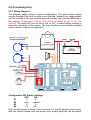
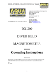
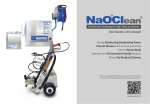
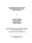
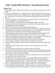
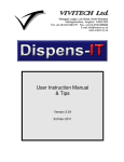
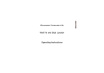
1
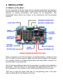
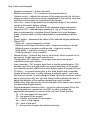
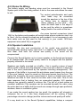
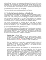
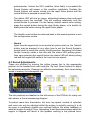
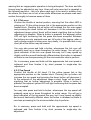
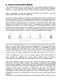
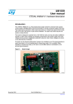
PROGRAMMABLE ENGINE
SOUND SYSTEM
designed by Alan Bond
Manual for
Potentiometer Control Option
Part Number 3803-221
the easy to program engine sound system, which allows
you to alter its character to suit your type of model
ABOUT THIS MANUAL
The user can choose to control this unit by either a standard radio control
receiver or by a throttle potentiometer and switches. Either mode of operation
may be selected by a configuration option switch.
Both options have differences in behaviour dictated by the control method
and require to be wired up differently. To avoid confusion, each option has a
dedicated manual. This manual covers the pot version only, if you also
require the RC version manual, then it can be downloaded from the product
page on the Technobots website.
This is the POTENTIOMETER CONTROL version of
the manual. Before proceeding further, check that
switch 4 of the configuration option switches is set to
the ON position to configure the unit for
POTENTIOMETER CONTROL.
INDEX
1. INTRODUCTION
2. OVERVIEW
3. SPECIFICATIONS
4. INSTALLATION
4.1 What’s In The Box
4.2 Connecting Up
4.2.1 Wiring Diagram
4.2.2 Provision of +5V Supply
4.2.3 Notes on Wiring
4.2.4 Speaker Installation
5. CONFIGURATION
5.1 DIP Switch Settings
5.1.1 Engine
5.1.2 Input
5.2 Battery Voltage
6. OPERATION
6.1 Guided Tour
6.2 The Neutral/Span/Neutral Zone Setting Button
6.3 Sound Adjustments
6.3.1 Tick Over
6.3.2 Top Speed
6.3.3 Number of Cylinders
6.3.4 Engine Voice
6.3.5 Horn
6.3.6 Idle Time Out
6.3.7 Volume Control
6.4 Engine Slow-Down/Stop
7. AUDIBLE WARNING SIGNALS
7.1 Voice Design
7.2 Warnings
7.3 Setting Confirmation
7.4 Error Conditions
8. VOICE DESIGNER MODE
9. SUPPORT
1. INTRODUCTION
This Sound System can synthesize a wide range of multi-cylinder
petrol/diesel engine sounds, all the major engine operating parameters (tick
over, top speed, number of cylinders, engine 'voice') being user adjustable by
a simple selector link and push-button interface. In all cases the engine sound
varies smoothly and proportionally with the throttle demand.
The engine has an adjustable idling time-out (typically set by the user to
around 20 seconds) after which it runs down and stops. Opening the throttle
again causes the engine to re-start following a short “cranking” sound.
Alternatively, the user may connect a toggle switch to start and stop the
engine at will. A push-button switch may also be connected to sound a built in
horn, whose pitch is adjustable.
Unusually, the Sound System also allows users to synthesize their own
engine sounds, full control of the pitch and duration of all the cylinders is
supported by a simple selector link and push-button interface.
The Sound System is simply controlled by connecting a potentiometer to its
input. The unit provides power to the potentiometer track and responds to the
voltage picked-off from the potentiometer wiper. This control potentiometer is
intended to be mechanically coupled to the potentiometer controlling the
motive power to the model. The Sound System WILL NOT accept a raw input
voltage from a potentiometer which is already connected to a speed
controller. Damage to one or both units is almost certain to occur!
'Neutral' (i.e. throttle closed) is expected to be set at one end of the
potentiometer, though the Sound System can cope with any neutral setting
within the entire range of the potentiometer. The neutral condition is indicated
by a case mounted status LED which assists in setting up the travel of
potentiometer. The range and the neutral zone of the throttle response may
also be set by a simple push-button procedure.
As the Sound System was originally designed for radio control installations,
the unit's electronics power supply was derived from the radio receiver. For
the pot version, the user must provide a separate source of 5V for the unit –
i.e. a 4AA cell NiMh battery pack or a 5V voltage regulator device coupled to
the main battery of the model. The loudspeaker derives its power from the
model's main propulsion battery, but a limit of 12v applies. Models using
higher voltages for traction will often use two or more 12v batteries in series
for that purpose and so 12V could be tapped off from the lower battery in the
chain, which is probably already utilised to power lights and indicators. See
the installation diagrams for examples of powering the unit.
The engine sound volume is adjustable by a PCB mounted rotary
potentiometer.
2. OVERVIEW
This Sound System carries on from where the original Technobots Petrol and
Diesel Sound units left off, and not so much replaces them as compliments
them, although the original units only featured radio control inputs. The
original Sound units continue to be small, affordable, entry-level products
whereas this Sound System in a slightly larger package scopes the sound
range of the two earlier Sound Systems and offers a whole host of additional
features as follows:•
•
•
•
Push button setting to match the neutral and span over the entire range
of the control potentiometer travel – this function also includes the
option to double the width of the neutral zone to make throttle setting
less critical for the engine's auto stop facility
Provision to connect a toggle switch for manual control of engine
start/stop
Provision to connect a push button to operate a horn - uses the engine
speaker, replacing the engine sound whilst operated - sounds at
maximum volume regardless of engine volume setting
Push button adjustment (during real-time operation) of
◦
Tick over
◦
Top speed
◦
Number of cylinders – from 2 to 6, though single cylinder operation is
simulated in voice #6 (see later)
◦
Engine 'voice' – 10 fixed, 10 custom (user defined) characters
◦
Pitch of the horn
◦
Idle timeout period (only valid for auto start/stop option) – 0 to 90
secs in 10 second increments, or continuous running
◦
Voice designer mode (for custom voices only)
▪
set pitch for each cylinder (128 possible values)
▪
set duration for each cylinder (5 possible values)
All settings are saved into non-volatile memory and are retrieved at
switch-on the next time the Sound System is powered up.
•
Volume control – controls engine sound volume only
3. SPECIFICATIONS
Speed demand sensing method
User connected throttle potentiometer. Impedance not critical, typically 1K to
10K values recommended, 20K maximum. Linear track required.
Neutral (idling) signal condition
May be set by push button anywhere within the potentiometer range
Throttle span adjustment
Ensures full throttle condition can be achieved for potentiometers producing
less than their full resistive range due to mounting/linkage considerations.
Receiver voltage (which powers the Sound System's electronics)
4.8V min to 6V max DO NOT USE A “6V” LEAD ACID BATTERY – a fully
charged one of these can output as much as 6.6V.
Speaker impedance
8 ohm minimum (Technobots part no. 2400-015 recommended)
Speaker supply voltage
From zero to '12V'. There is a 16V rated capacitor across this input, exceed
this voltage at your peril! A fully charged 12V lead acid battery will be in the
region of 13.5V and hence is ok, but 12 cells NiMH, a nominal '14.4V', will
exceed 16V when fully charged and is NOT ok.
Engine 'voices'
20 different voices (10 fixed, 10 user defined), encompassing 'petrol' and
'diesel' characters
Number of cylinders
Selectable from 2 to 6, though single cylinder operation is simulated in voice
#6 (see later)
Engine stop/start
Choice of automatic or manual – automatic is determined by the throttle
demand and the idling period, whereas manual responds directly to a user
fitted toggle switch.
Engine idle timeout
For the case of automatic start/stop, the idling period may be set from zero to
90 seconds in ten second increments or optionally continuous running may
be set.
Engine Slow Down/Stop
Choice of fast or slow stop to simulate engines with normal or large heavy
flywheels.
4. INSTALLATION
4.1 What's In The Box?
On the underside of the box there are four screws which allow the casing to
be removed from the bottom plate to reveal the Sound System inside for the
purpose of making connections and setting up its parameters. The
photograph below shows the location of the connections and the principal
controls.
Make connections to the Sound System (as described later), configure it and
try it out with the case removed. Make sure the Sound System is not placed
on a metallic surface or surface contaminated with metal debris, placing it on
the base plate is recommended.
Only fit the Sound System back into its case when it is ready to be installed in
the model. Note the case is for mechanical and splash protection only, it is
NOT waterproof, so its location in the model should take this into account.
Take care to align the status LED with its corresponding hole in the case
when re-fitting the Sound System into its box.
Key to above photograph
•
•
•
•
•
•
•
•
•
•
•
•
•
Speaker connection – 8 ohm minimum
Battery connection – '12v' maximum (see specifications)
Volume control – adjusts the volume of the engine sound, but the horn
always sounds at maximum volume regardless of this setting, note that
minimum volume does not yield silence (by design)
Hi/Lo link – used to best match the mechanical range of the volume
control to the user's battery voltage
'Up' button – increases the value of the selected engine parameter
Keypress LED – acknowledges pressing of ‘Up’ or ‘Down’ buttons –
also on permanently to indicate Sound System is in voice designer
mode, in which case it briefly extinguishes to acknowledge a button
press
'Down' button – decreases the value of the selected engine parameter
Status LED
Solid red – engine stopped in neutral
Blinking red at engine revolution rate – engine is running in neutral
Blinking green at engine revolution rate – engine is running
Solid green – engine is running at full speed
Flashing orange – error condition
Neutral button – press at any time to set neutral, press at switch-on to
set neutral, throttle span and neutral zone
Configuration DIP switches – set engine start auto/manual and
rc/potentiometer input options
Input channels - Ch1 accepts input from a throttle potentiometer. Ch2
accepts input from a toggle switch for manual start/stop of the engine.
Aux channel accepts input from a push button switch to sound the horn
'D' button – in normal running this is the 'data' button and via audible
'beeps' allows the user to verify settings of cylinder count, 'voice' and
idle time-out values. In voice designer mode, this is the 'duration' button
and in conjunction with the ‘Up’ and ‘Down’ buttons allows the user to
adjust the duration of the exhaust pulses from each cylinder.
Additionally, at power-up only, this button sets either fast or slow engine
run-down/stop (toggle action)
Engine parameter selection links – move the yellow jumper link to the
following positions, marked on the PCB, in order to adjust the
appropriate parameter by means of the 'Up' and 'Down' buttons
Tk – tick over speed of the engine
TS - top speed of the engine
Cy - number of cylinders in the engine
Vo – 'voice' of the engine
Hn – pitch of the horn
Ti – time period of engine idle before auto-stop
4.2 Connecting It Up
4.2.1 Wiring Diagram
The diagram below shows a typical configuration. The push button switch
may be omitted if the horn function is not required. Similarly, the toggle switch
may be omitted if the user prefers automatic rather than manual start/stop of
the engine. Configuration Options DIP switch #4 must be set to the ON
position. DIP switch #2 can be set to ON or OFF to select either manual or
automatic start/stop of the engine. The horn function is permanently enabled
and so does not require configuration.
Configuration DIP Switch Settings
OFF
ON
#1
X
X
#2
auto
manual
#3
X
X
#4
r/c
pot
If the throttle sense is found to be reversed (i.e. the full speed sound occurs
with the throttle closed and vice-versa) then simply swap the red and black
wires on the throttle potentiometer or invoke the neutral/span setting
procedure at power-up with the throttle in the desired tickover position.
4.2.2 Provision of +5V Supply
In RC (radio control) systems, for which the Sound System was originally
intended, this supply usually comes from a nominal 5V BEC (battery
eliminator circuit) which is already in place to supply the receiver and servos.
Thus for non-RC equipped systems the user must provide this supply
themselves, for which there are three options:•
•
•
A separate '5V' battery pack
A commercial BEC
A home-made 5V voltage regulator
A battery pack can be made up using 4 AA cells in a
suitable holder – preferably a type that is both enclosed
and switched, such as Technobots part 1063-063. Either
re-chargeable NiMh or primary (single use) cells may be
used – the former yielding a nominal 4.8V (1.2V per cell)
or the latter yielding 6v (1.5V per cell) due to the
different battery chemistries involved.
Note that 4 fresh primary cells cannot exceed the 6V maximum rating of the
Sound System but using a nominal '6V' lead acid battery certainly will - a fully
charged one of these can output as much as 6.6V.
A typical commercial 5V BEC is shown here, which
can drop the typical 12V speaker supply down to the
requisite 5V, thus avoiding the logistics of
accommodating and charging an extra set of
batteries with the benefit that the main power switch
will also switch off the 5V output from this unit. It also
benefits from being supplied with a standard RC
lead/plug which is directly compatible with the Sound
System. The unit shown is Technobots part 1062-017
The final option is to make your own 5V regulated
supply using a three terminal voltage regulator such
as the L7805 - Technobots #2230-110. Depending
on the main battery supply voltage you may need to
use a heatsink. This option is only suitable for those able to
design and construct such circuitry themselves.
4.2.3 Notes On Wiring
The battery supply and speaker wires must be connected to the Sound
System prior to the box being refitted. A slot in the case side allows the wires
to exit.
The control potentiometer and push
button leads may be connected
through the aperture in the top of the
box, taking care to observe the
polarity marking on the label – this
means the black lead to the edge of
the box and the white (or sometimes
orange) lead to the centre of the box.
The screw terminal connectors (rated
10A) for the battery and speaker will accept wires whose conductor size is up
to 1mm². As the currents involved are quite modest it is not necessary to use
thick cable such as that used for the motor(s) in your model. 16/0.2mm
equipment wire (rated 3A) is suggested.
4.2.4 Speaker Installation
Inevitably the size and construction of the model may preclude the
recommended speaker being used and if in addition its installation is less
than ideal, then both the volume and quality of the sound will be
compromised.
Connect the Sound System up to a loose speaker on the bench and prepare
to be disappointed! The sound quality needs to be judged with the speaker
properly mounted in the model.
Speakers are ideally mounted on a baffle – this is usually a piece of wood
whose width is about twice the diameter of the cone with a hole in it about the
size of the cone (determined by the speaker mounting arrangement). The
purpose of the baffle is to prevent the anti-phase sound waves from the rear
of the cone 'leaking' round to cancel out the sound waves from the front. The
higher the frequency the more sound tends to travel in straight lines and is
therefore less able to 'leak' round to the other side of the cone. Thus it's the
bass response that is lacking from an unmounted speaker. Hi-fi speaker
cabinets are generally sealed to achieve this. The hull of a boat makes an
excellent substitute if the speaker can be mounted beneath the cabin using
the entire deck as a baffle and the sound can escape through open portholes,
windows, doors or ventilation grilles.
If you make the sound sealing box too small, the speaker will struggle to
compress the air in it (the cone displacement will be making a large
percentage volumetric change) and the volume and sound quality will suffer.
If in any doubt as to the Sound System's capabilities, kidnap a compact
music-centre loudspeaker, connect it up and hear the result. Anything
sounding less rewarding than this represents the magnitude of your personal
battle to defy the laws of acoustics!
To appreciate the importance of the all the above and the dividends repaid by
a bit of effort, the following testimonial, for the original Technobots (Petrol)
Sound unit is published below (by courtesy of Peter Bone)
Just thought I’d let you know that I got the sound unit installed and up
and running for the Southend Model Power Boat club Annual Festival this
weekend. Our guest judge was Andy Coulson of the Southwater
Dabblers Club and he judged my boat ‘Best in Show’! I’m sure the sound
unit tipped the balance and helped me win.
The sound unit is terrific and attracted a lot of attention and several
people asked me where it came from.
As you quite rightly said, the really difficult bit is mounting the speaker
and getting the sound out. The model is Andy Griggs’ 1/12th scale
Cygnus 33 the one with the ‘bulbous’ bow. After quite a lot of
experimentation I’ve mounted the speaker on a relatively small wooden
baffle low down in the bow, facing upwards at an angle towards the
underside of the wheelhouse floor. I put a cardboard tube (from a reel of
tape) over the speaker, then I found that an empty container of Cadbury’s
cocoa powder just happened to be a nice sliding fit inside the cardboard
tube, by sliding the cocoa container in and out (and shortening it) with the
open end facing the speaker and the closed end upwards, I found I could
‘tune’ the note. The cocoa container is a cardboard tube with a metal
bottom and the thin metal bottom needed a bit of ‘damping’ which I did
with a disc of self adhesive felt, then I drilled a hole in the bottom of the
container and fitted a piece of plastic tube about 15mm dia, this
terminated just under the wheelhouse. I finally drilled a few holes in the
wheelhouse floor in places where they were not visible from the inside as
the wheelhouse is nicely fitted out and I didn’t want to spoil the look from
the inside.
5. CONFIGURATION
This section expands the information about the DIP switch settings given in
the installation instructions above, and also introduces the battery voltage
setting (Hi/Lo) link.
5.1 DIP Switch Settings
The following three options which relate to configuration of the radio control
input channel(s) are located on the red 4 way DIP switch (DIP=Dual In-line
Plastic). The switch positions for the various options are illustrated below.
OFF
ON
auto
manual
1 [unused]
2 ENGINE
3 [unused]
4 INPUT
radio control
potentiometer
5.1.1 ENGINE
•
Auto Start/Stop - the engine starts automatically when the throttle is
opened. The engine stops automatically after a period of idling in the
neutral condition (indicated by the status LED on the case showing
red). The user may set the idling period prior to the engine stopping
in the range 0 to 90 seconds in 10 second increments. A further
option is to have the engine running continuously.
•
Manual Start/Stop – the engine starts or stops in direct response to
the signal received on the Ch2 input connector. Simply opening the
throttle will not start the engine (though the boat/vehicle will move
accordingly) and likewise the idling time-out value set by the user is
ignored if this option is selected.
5.1.2 INPUT
•
•
Radio Control – the inputs are configured to accept signals from a
standard radio control receiver in the 1mSec to 2mSec range
Potentiometer – the inputs are configured to accept a potentiometer
and toggle/push-button switches
DIP Switch #4 is checked at power-up and the unit then assumes the
control method set by the switch position. Subsequent operation of DIP
Switch #4 will not change the mode of operation, the unit producing an
error buzz until the switch is returned to the position it occupied at
power-up.
5.2 Battery Voltage
The remaining option is in an isolated location and its header is served by a
blue jumper link (J7) whose options are marked 'Hi' and 'Lo'. This option best
matches the (mechanical) range of the volume control to the loudspeaker
voltage supply. For example, in the case of 6V and 12V systems, if only half
volume can be achieved or full volume occurs at half rotation of the volume
control then the jumper link needs to be altered to best match your battery
voltage. The 'Lo' setting is optimised for 6V and 7.2V batteries and the 'Hi' for
12V batteries. The setting for intermediate battery voltage conditions is best
determined by experiment.
6. OPERATION
6.1 Guided Tour
The Sound System may be operated immediately after installation and the
information below is for the user to effect a quick guided tour of the capability
of the Sound System. It is assumed that all the configuration links have been
set to match the connected input channels and the main battery voltage as
per the previous installation instructions. Thus, depending on the scope of the
installation, not all functions described in the tour will be available to all users.
It is also assumed that the user has familiarised themselves with the location
of the various selection links and push buttons.
With the model on a stand to allow the propeller(s), wheels or tracks to run
free, first zero the throttle potentiometer and power the model. The status
LED should light up a solid red, signifying the throttle channel is in the
'neutral' condition and the engine should be silent.
However, if your closed throttle does not match the factory default neutral
then at this point the status LED may be extinguished, or in the case of the
auto start option or the start/stop function assigned to a toggle switch, the
engine may have already started up on its own and the status LED be pulsing
green at the engine revolution rate.
If so, press the neutral button and the status LED will go red, indicating the
new neutral point has been set. If the engine was already running, the Sound
System will settle to a slow idle and the status LED will be pulsing red at the
tick over rate. If the engine was stopped the status LED will be showing a
solid red. The neutral point is saved to memory and will match that of the
throttle control the next time they are used.
If the Sound System is already running, then after approximately 20 seconds
(factory default setting) of idling in neutral it will slow down and stop.
Alternatively operate the toggle switch to stop the engine.
Depending on your installation, the engine may now be started in two
possible ways:•
opening the throttle
•
operating the toggle switch
The speaker should issue a short cranking sound and the 'engine' should
start and smoothly run up to full speed as the throttle is progressively opened,
the status LED now showing green and pulsing increasingly faster with
engine speed. At full excursion of the throttle potentiometer the LED should
go solid green, signifying the engine is in receipt of the maximum possible
speed demand. With the factory default 'span' setting this may occur slightly
prior to full excursion, or maybe not at all. Setting the full dynamic range of
the Sound System to match the 'span' of your control potentiometer is
covered in the next part of this manual and need not be done for the
purposes of the 'tour'.
With the throttle closed the engine should return to idling speed and the
status LED should be pulsing red. The engine may now be switched off by
operating the toggle switch,or waiting for (the factory default of) 20 seconds –
or as appropriate to your configuration. The status LED will show solid red
when the engine stops.
At some convenient point, the volume control can now be checked to operate.
Note that (by design) the lowest volume setting does not yield complete
silence, but is plenty quiet enough for the workshop or small exhibitions etc.
Assuming a suitable loudspeaker and a decent acoustic installation, running
on 12V at maximum volume the Sound System will be clearly heard right
across a large pond or in a large noisy exhibition. Note the installation section
gives information about best matching the range of the volume control to your
battery voltage.
Now for the fun! Start the engine and let it idle. Place the yellow jumper link in
the 'Tk' position and then set the tick over speed to your personal preference
by use of the ‘Up’ and ‘Down’ buttons. A short stab of the appropriate button
will effect a small change in tick over speed. The adjacent yellow LED will
light for the duration of the press to provide visual confirmation of the press.
Holding the button pressed will cause the speed to gradually ramp up or
down and the button can be released at the desired setting.
At the extremes of the setting range a short high-pitched beep will be heard
signifying that no further adjustment is possible. This scheme is used
throughout the Sound System to indicate the limits of adjustment have been
reached.
Now advance the throttle to full speed, move the yellow jumper link to 'TS'
and use the ‘Up’ and ‘Down’ buttons in the same manner as before to set the
desired top speed.
At a fairly low throttle setting (suggested condition to best hear the variations)
move the yellow jumper link to the 'Cy' position and use the ‘Up’ and ‘Down’
buttons to adjust the cylinder count to personal taste. Unlike the previous use
of the ‘Up’ and ‘Down’ buttons, holding a button pressed does not cause
repeated adjustment, the buttons must be released to take effect. This makes
for a far more positive selection 'feel'.
Depending on the number of cylinders chosen, the tick over and top speed
may now benefit from being re-adjusted to suit the character of the engine
afforded by its new cylinder count.
With a 4 cylinder engine set to a fairly low speed (suggested condition to best
hear the variations) move the yellow jumper link to the 'Vo' position and use
the ‘Up’ and ‘Down’ buttons to cycle through the different engine characters
available. The same positive selection style applies to operation of the
buttons. The first ten 'voices' are factory presets and are fixed for all time,
whereas the following ten voices (initially supplied with the corresponding
factory presets installed in all of them, as a departure point for
experimentation) are able to be adjusted by the user and their settings saved
in memory for future use. A short “deedle-dee” sound warns the user that a
custom voice capable of user adjustment has been selected. Development of
custom engine sounds is covered in SECTION 8.
Moving the yellow jumper link to the 'horn' position allows the user to alter the
pitch of the horn from a deep bass fog-horn to a high pitched air-horn sound,
by use of the ‘Up’ and ‘Down’ buttons. The horn increments or decrements in
pitch for each press of the ‘Up’ or ‘Down’ buttons and sounds at the current
volume level setting.
Note the horn sound can be previewed this way even if the horn option has
not been selected in the user configuration of the Sound System, though the
volume control would need to be increased to its maximum setting to properly
judge the final effect.
If configured, operating the horn switch will now sound the horn at full volume,
regardless of the volume control setting. This is in view of the importance of
the horn as a collision warning device.
If the Sound System has been configured for auto stop/start then the period
of idling before the engine stops can be set by moving the yellow jumper link
to the 'Ti' position. The ‘Up’ and ‘Down’ switches adjust the idling period in
approximately 10 second increments between 0 and 90 seconds. This link
setting is ignored of course if the Sound System has been configured for
manual start/stop of the engine. As the effect of this adjustment won't be
apparent for some period of time, the Sound System will issue a number of
medium pitched beeps to indicate the setting now selected. Each beep
represents 10 seconds of idling time (the resolution of adjustment). Silence of
course represents zero seconds. At what would be the 100 second option
position, the Sound System issues 10 beeps but continuous engine running is
now selected – i.e. the engine will only stop when the power to the Sound
System is removed.
A fourth pushbutton marked 'D' will later be used in the Voice 'D'esigner
mode, but during normal operation it doubles up as a 'D'ata button. If in doubt
as to the selected 'voice', number of cylinders or timeout values, pressing the
'D' button with the yellow jumper link in the corresponding position will cause
the Sound System to emit a series of medium pitched 'beeps' related to the
setting of the chosen parameter. These are distinctly different from the higher
pitched 'beeps' indicating the extremes of adjustment. In the case of the user
adjustable voices, the beeps are preceded by the “deedle-dee” sound as in
the normal voice selection. Pressing the ‘D' button with the jumper link in tick
over, top speed or horn positions will cause a low pitched buzz, indicating that
an inappropriate data request has been made.
That concludes the quick guided tour of the Sound System.
6.2 The Neutral/Span/Neutral Zone Setting Button
This button accesses two distinct procedures. The first procedure is really a
configuration issue and sets up the neutral and then the span parameters to
match those of the control potentiometer being used with the model and the
width of the neutral zone to best suit the user. This procedure is only available
at power-up time, and should not need to be repeated unless a different
control potentiometer is subsequently fitted or its linkage is changed.
The second procedure may be accessed at any time whilst the Sound
System is operating and sets up the neutral alone. This action does not affect
the 'span' or neutral zone of the Sound System, and so it should only be used
to correct minor deviations from neutral (i.e. 'drift').
The Sound System assumes a full range of control potentiometer movement,
occurs but mounting/linkage considerations may preclude this, in which case
without a span adjustment the user could not achieve the full speed range
that the Sound System is capable of. Thus some adjustment of span to match
the user's control potentiometer installation is desirable.
•
Neutral , Span & Neutral Zone
IMPORTANT – this configuration routine can only be entered at powerup. Prior to switching on the Sound System, the throttle potentiometer
should be set to its desired (physical) neutral position. Press and hold
the 'Neutral' push-button prior to powering up the Sound System.
After the Sound System is powered up, continue holding the button until
the status LED shows solid red, to signify the successful setting of
neutral. When, and only when, the status LED is red, release the push
button and proceed to set up the span.
Having released the button, the status LED will now slowly flash red,
inviting you to advance to the full throttle position. Once the throttle
control has exceeded 50% of the larger of the two potential spans (if
the neutral setting is asymmetric) the status LED will now rapidly flicker
red and when the user has completed moving the throttle to its
maximum excursion, the neutral button should be pressed a second
time. The gain of the Sound System's throttle channel is now set such
that full engine speed matches full movement of the control
potentiometer. Unless the 50% condition (slow flash) is exceeded the
Sound System will remain in this condition indefinitely. Similarly the
Sound System will remain locked into the rapid flicker phase until the
neutral button is pressed a second time.
The status LED will now go green, alternating between slow and rapid
flickering every few seconds. This will continue indefinitely until the
neutral button is pressed. For the factory default neutral zone setting,
press the neutral button during the slow flicker phase, or to double its
width press the button during the rapid flicker phase.
The throttle must be then be returned back to the neutral position to exit
this configuration routine.
•
Neutral
Apart from the opportunity to set neutral at system start-up, the ‘Neutral’
button may be pressed at any other time to set the Sound System's
neutral point to match the current throttle position. Assuming the closed
throttle currently yields a fast idle with the status LED pulsing green,
then upon pressing the neutral button the status LED will show pulsing
red and the engine will settle to the true tick over speed.
6.3 Sound Adjustments
These are effected by moving the yellow jumper link to the appropriate
position on the header block and using the ‘Up’ and ‘Down’ buttons to adjust
the selected parameter. Changes are effective immediately, their values being
saved in memory for subsequent use.
The link positions are labelled on the silk-screen of the PCB but for clarity are
also shown in the accompanying diagram.
To protect users from themselves, tick over, top speed, number of cylinders
and voice can only be adjusted whilst the engine is actually running (it is all
too easy to completely muddle your settings without the audio feedback of
what the engine is doing!) Thus, attempting to set these parameters whilst the
engine is stopped will result in the speaker emitting a low pitched buzz,
warning that an inappropriate operation is being attempted. The horn and idle
timeout may be adjusted at any time. Users will note some text is repeated in
the following sections – this is to allow each topic to be read in isolation from
the others, but there are in fact a few subtle differences so please read each
section thoroughly to become aware of them.
•
6.3.1 Tick over
Position the throttle at neutral position, ensuring that the status LED is
pulsing red. Fit the yellow jumper link in the appropriate position on the
header block. Pressing the up button will increase the tick over speed
and pressing the down button will decrease it. At the extremes of the
adjustment range a short 'beep' will be heard, signifying that no further
adjustment is possible. When a button is pressed, the adjacent yellow
LED will light confirming that the press has been accepted. Because
the buttons are only scanned once per full cycle of the engine, when a
multi-cylinder engine is ticking over very slowly, it is possible that a very
short jab of the button may be missed.
You may also press and hold a button, whereupon the tick over will
gradually ramp up or down throughout its entire range. You will get a
good indication of the tick over speed this way, but it may speed up
slightly and thus sound fractionally different when the button is released
as there is now less processing for the microcontroller chip to perform.
So, in summary, press and hold until the approximate tick over speed is
achieved and then finalise it by short presses to single-step the
adjustment.
•
6.3.2 Top Speed
Position the throttle at full travel. Fit the yellow jumper link in the
appropriate position on the header block. Pressing the up button will
increase the top speed and pressing the down button will decrease it.
At the extremes of the adjustment range a short 'beep' will be heard,
signifying that no further adjustment is possible. When a button is
pressed, the adjacent yellow LED will light confirming that the press has
been accepted.
You may also press and hold a button, whereupon the top speed will
gradually ramp up or down throughout its entire range. You will get a
good indication of the top speed this way, but it may speed up slightly
and sound fractionally different when the button is released as there is
now less processing for the microcontroller chip to perform.
So, in summary, press and hold until the approximate top speed is
achieved and then finalise it by short presses to single-step the
adjustment.
•
6.3.3 Number of cylinders
Be sure to move the throttle up and down during this procedure to best
appreciate the overall effect of this adjustment. Fit the yellow jumper
link in the appropriate position on the header block. Pressing the up
button will increase the number of cylinders and pressing the down
button will decrease it. At the extremes of the adjustment range a short
'beep' will be heard, signifying that no further adjustment is possible.
When a button is pressed, the adjacent yellow LED will light confirming
that the press has been accepted.
The press and hold function is not appropriate for this adjustment.
Holding the button down will actually stop the engine sound altogether.
The cylinder count is only altered when the button is released. Waiting
for the button to be released has the effect of 'debouncing' the switch
contacts so accidental skipping of a setting is avoided and the user
experiences a very positive selection 'feel'.
Note that in the factory preset 'voices', some cylinders have a zero
length exhaust pulse – this gap in the rhythm usually produces a very
satisfying 'throbbing' sound, so for example in voice #1, this gap is
introduced in cylinder 5, so there are 4 exhaust pulses but for reporting
purposes the engine considers itself to be a 5 cylinder engine. A single
exhaust pulse on its own does not sound very convincing, but in voice
#6, only cylinders 1 & 2 are used, the remaining cylinders staying quiet
– thus in 5 or 6 cylinder mode the two 'blats' close together followed by
a long gap *do* sound very much like a single cylinder engine. So
although the Sound System only nominally supports 2 to 6 cylinder
operation, a single cylinder sound can be simulated.
•
6.3.4 Engine 'Voice'
Be sure to adjust the throttle up and down and/or adjust the number of
cylinders during this procedure to best appreciate the overall effect of
this adjustment. Fit the yellow jumper link in the appropriate position on
the header block. Pressing the up or down buttons will step through the
different 'voices' available. At the extremes of the adjustment range a
short 'beep' will be heard, signifying that no further adjustment is
possible. When a button is pressed, the adjacent yellow LED will light
confirming that the press has been accepted. To identify the 'custom'
voices, capable of being adjusted by the user, a short 'deedle-dee'
sound is played prior to a custom voice being asserted.
The press and hold function is not appropriate for this adjustment.
Holding the button down will actually stop the engine sound altogether.
The 'voice' is only altered when the button is released. Waiting for the
button to be released has the effect of 'debouncing' the switch contacts
so accidental skipping of a setting is avoided and the user experiences
a very positive selection 'feel'.
•
6.3.5 Horn
This may be adjusted at any time whether the engine is running or not.
However, it cannot be adjusted whilst the horn is being asserted from
the user's horn switch. If the engine is running, it replaces the engine
sound each time an adjustment button is pressed. Users may prefer to
stop the engine before commencing adjustment – but this is not
essential. Fit the yellow jumper link in the appropriate position on the
header block. Pressing the up button will increase the pitch of the horn
and pressing the down button will decrease it. At the extremes of the
adjustment range a short 'beep' will be heard, signifying that no further
adjustment is possible. When a button is pressed, the adjacent yellow
LED will light confirming that the press has been accepted.
The horn will sound for the duration of the button press and the pitch
heard is saved when the button is released. Waiting for the button to be
released has the effect of 'debouncing' the switch contacts so
accidental skipping of a setting is avoided and the user experiences a
very positive selection 'feel'.
•
6.3.6 Idle Time-out
This may be adjusted at any time whether the engine is running or not.
Fit the yellow jumper link in the appropriate position on the header
block. Pressing the up button will increase the timeout value by
approximately 10 seconds and pressing the down button will decrease
it by the same amount. To indicate the setting achieved, a succession of
medium pitched 'beeps' will sound – each 'beep' indicating a unit of
approximately 10 seconds [e.g. 2 beeps=20 seconds, 3 beeps=30
seconds]. No beep=0 seconds delay of course. At what would be the
100 second option (10 'beeps') the engine enters a continuous running
mode and will only stop when power is removed. At the extremes of the
adjustment range a higher pitched 'beep' will be heard, signifying that
no further adjustment is possible. When a button is pressed, the
adjacent yellow LED will light confirming that the press has been
accepted.
The press and hold function is not appropriate for this adjustment.
Holding the button down will actually stop the engine sound altogether
(if running). The timeout value is only altered when the button is
released. Waiting for the button to be released has the effect of
'debouncing' the switch contacts so accidental skipping of a setting is
avoided and the user experiences a very positive selection 'feel'.
Note the time-out periods are approximate – don't expect stop-watch
precision here! There is no direct means of measuring time in the
microcontroller chip, so engine revolutions are counted instead,
appropriate compensation being applied at the different tick over
speeds. But this means that different durations of the cylinder sounds in
the various 'voices' can cause a small variation in the time-out value as
indeed can a fractionally offset throttle as the idling speed can have
some variation in the neutral zone, particularly if the larger of the two
neutral zone options has been selected.
•
6.3.7 Volume Control
If only partial volume can be achieved or full volume occurs at partial
rotation of the volume control then the separate blue link on the 3 pin
header JP7 whose insertion positions are marked 'Lo' and 'Hi' needs to
be altered to best match your battery voltage. The 'Lo' setting is
optimised for 6V and 7.2V batteries and the 'Hi' for 12V batteries. The
setting for intermediate battery voltages is best determined by
experiment.
6.4 Engine Slow Down/Stop
Two different rates of engine slow down/stop are available to simulate
engines with large heavy flywheels (typically marine) or standard flywheels
(typically road vehicles). To change between these variants hold the 'D' button
pressed at power-up. Either a short or long 'beep' will be heard signifying the
slow down rate now selected. Repeat the above process to swap back.
7. AUDIBLE WARNING SIGNALS
These provide feedback to the user in the categories of voice design,
warnings, setting confirmation, and error conditions. For consistency, each
category has a distinctive sound associated with it.
7.1 Voice Design
Characterised by a short tune (what else!)
7.2 Warnings
Characterised by a single high-pitched 'beep'. This occurs during
normal operation when pressing the ‘Up’ or ‘Down’ keys and indicates
that the attempted adjustment has reached the limit of its range.
7.3 Setting Confirmation
Characterised by a medium-pitched 'beep' or succession of 'beeps'.
•
•
•
Idle timeout - the effect of adjusting all the other parameters can be
heard immediately, whereas this setting could take up to 90 seconds to
make itself known. Thus, each time the idle timeout is adjusted (in 10
second increments) a succession of 'beeps' indicates the value just set.
Obviously at the extremes of the range the high pitched warning 'beep'
will be heard instead
Number of cylinders – pressing the 'D' button will cause a succession of
'beeps' corresponding to the current cylinder setting
Voice - pressing the 'D' button will cause a succession of 'beeps'
corresponding to the current voice setting
7.4 Error Conditions
Characterised by a low 'buzz'. This indicates that the attempted
adjustment is inappropriate in the current situation and lasts for the
duration of the button press or DIP switch change. They result in the
following situations:•
Attempting to adjust tick over, top speed, number of cylinders or voice
whilst the engine is in the stopped condition. It is all too easy to
completely muddle your settings without the audio feedback of what the
engine is doing!
•
Attempting to enter the voice designer mode to modify a factory preset
'voice'
•
Attempting to adjust the pitch / duration of a cylinder beyond the range
of the current setting i.e. adjusting cylinder 5 on a 4 cylinder engine
•
Attempting to request the setting status of tick over, top speed or horn
•
Attempting to change the input control method (radio control or
potentiometer) at any time other than power-up
8. VOICE DESIGNER MODE
This mode allows the user to develop their own custom engine sounds for
'voices' 11 to 20 inclusive. All settings are saved in the Sound System's
memory for subsequent recall the next time the Sound System is powered up.
First, a description of how the sound is produced, such that the user may
better appreciate what they are adjusting!
The engine sound synthesis is based on emitting a short pulse of 'white noise'
for each cylinder in turn, this representing the pulses of exhaust gas from
each cylinder emerging from the exhaust pipe. Each cylinder pulse lasts for a
preset 'duration' and the nature of the burst of transitions within that pulse
determines the 'pitch' of the 'white noise'. The pitches and durations for each
cylinder are stored in the 'voice' constants in the program. When, in the
example below, the sequence of 4 different exhaust gas pulses is repeated it
gives rise to a rhythmic beat. The equal length silent periods between pulses
are increased or decreased in unison to vary the apparent engine speed.
Note that strictly speaking 'white noise' is random and neither does it possess
'pitch', but to simulate 'while noise' the microcontroller chip in fact produces a
pseudo random data stream which by definition is repeatable so each
cylinder sounds the same each time it fires. The clock rate of the pseudo
random data stream can also be varied which gives tones ranging from a
growl to a hiss. For ease of explanation this has been referred to as its 'pitch'.
Thus, in designing a 'voice' the user simply assigns a pitch and duration to
each cylinder. As supplied, the custom 'voices' initially match the factory
preset ones, thereby providing a good departure point for experimentation.
The Voice Designer mode can only be entered at power-up by pressing
BOTH the ‘Up’ and ‘Down’ buttons. The buttons should both be pressed
before power is applied. A short tune will play to indicate the mode has been
entered successfully and the yellow keypress LED will be lit throughout the
duration of this mode to serve as a reminder to the user. The LED will
extinguish for the duration of a button press to acknowledge its operation.
Attempting to enter this mode when one of the ten factory preset voices is
selected will result in a low-pitched error buzz for as long as the keys remain
pressed.
The group of six headers associated with the single yellow jumper link now
relate to cylinders 1 to 6 and the ‘Up’ and ‘Down’ buttons now increase or
decrease the pitch of the sound for the selected cylinder. Each cylinder will
accept 128 different pitch values. As before, a single high pitched beep
signifies the limits of adjustment have been reached. Similarly, a low pitched
buzz signifies an inappropriate adjustment is being attempted (such as
adjusting cylinder 5 on a four cylinder engine).The higher pitches tend to give
the sharp clatter of tappets and the lower pitches give more 'body' to the
sound. A successful voice usually contains a range of pitches and durations
to give the engine its characteristic 'beat'.
If the 'D' button is pressed and held then the ‘Up’ and ‘Down’ buttons now
adjust the duration of the exhaust pulse from the selected cylinder. Each
cylinder will accept 5 different duration values. A single high pitched beep
signifies the limits of adjustment have been reached. Similarly, a low pitched
buzz signifies an inappropriate adjustment is being attempted (such as
adjusting cylinder 5 on a four cylinder engine). The lowest duration is zero
and setting one of the cylinders to this value will usually produce a 'throbbing'
sound. It then becomes a moot point as to how many cylinders the engine is
operating on but the cylinder setting confirmatory beep (only available in
normal mode) will report any zero duration cylinders as being present.
As the group of six headers no longer control the normal functions (ie tick
over, top speed etc) these parameters should be set – particularly the number
of cylinders – prior to entering this mode. However, the throttle channel does
remain active so may be swept up and down during the course of 'voice'
design to judge the overall effect.
To facilitate skipping through 128 pitch values, a held key is acted upon each
full cylinder cycle of the engine, so increase the engine speed to facilitate
more rapid progress. A six cylinder engine at top speed takes around 20 secs
to cover the range whereas a two cylinder engine takes around 6 secs.
The changes can be quite subtle so a short jab of the ‘Up’ or ‘Down’ key
which increments or decrements the pitch by one unit should be thoroughly
explored. To prevent a slow finger response causing the pitch to skip a value
the engine should be running at a slow tick over when fine-tuning the sound.
A good sound is a combination of various pitches and durations across ALL of
the cylinders, so adjusting one cylinder is unlikely to yield a result in itself.
Note that not all combinations of pitch and duration make for entirely sensible
sounds.
To exit the voice designer mode the 5V power must be switched off.
9. SUPPORT
Any problems or queries relating to the connection or operation of the Sound
System are best dealt with by first visiting technobotsonline.com to see if
others have experienced your problem and an answer has already been
posted there. If not, then you can submit your query with the benefit that the
answer you get will be available to future visitors.
To read/receive support, visit www.technobotsonline.com, type in ‘engine
sound’ in the Search box. This will list the entire range of engine sound units.
Select the Programmable Engine Sound System variant and then click on its
Q and A tab. This lists all the questions and answers relating to this product. It
may also be worth checking postings relating to the single sound petrol,
diesel and steam units which have already been in the field for several years
as generic problems may have been covered there. Note that the questions
and answers may well spill over to further pages.
Technobots Ltd
60, Rumbridge Street, Totton, Hants SO40 9DS
Telephone: +44 (0)23 8086 4891
www.technobotsonline.com
Visit our website to see our range of over 8,000 products for
the electronics, modelling and engineering enthusiast.