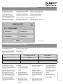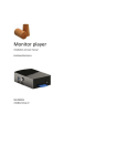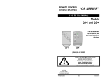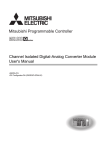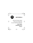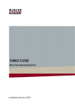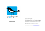
1
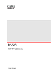
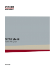
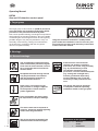
Operating Manual
KD780
Gas and CO detection control panel
1. Target group
The target group of this manual are qualified personnel
of the gas safety and regulating technology, skilled
personnel or the persons instructed by them.
Due to their specialist training, knowledge and experience
and knowledge of standard regulations, they are capable
of evaluating the work assigned to them and recognising
possible dangers. Only they are permitted to carry out
assembly, commissioning, settings and maintenance
on the devices in compliance with the recognised
rules for occupational safety.
Hang this instruction manual in a readily visible
place inside the installation room! Do not carry out
any work until you have read the safety instructions
of this instruction manual.
2. Warnings
2.1 General warnings
The recognised occupational safety
rules and accident prevention regulations must be observed and, if necessary, personal protective measures
must be taken.
All adjustments and settings should
only be performed in accordance
with the instruction manuals of
the connected machines.
Never carry out work as long as
gas pressure or voltage is applied.
Avoid open fire. Please observe
public regulations.
Protection from environmental
impacts and weather conditions
(corrosion, rain, snow, icing, humidity
(e.g. by condensation), mould,
UV radiation, harmful insects,
poisonous, corrosive solutions/liquids
(e.g. cutting and cooling fluids )),
must be guaranteed. Depending
on the installation site, it may be
necessary to take protective measures.
The device may only be operated
in compliance with the operating
conditions stated on the type plate.
M • Edition 09.14 • Nr. 266304
Prior to assembly, the device must
be inspected for transport damage.
1 … 24
The device must not be exposed to
open fire. Protection against lightning
strikes must be guaranteed.
The device must be protected from
vibrations and mechanical impact.
Explanation of the symbols
1, 2, 3,... = Order of
action
• = Instruction
2.2 Designated use
The device is used in accordance with its designated use
if the following instructions are observed:
• Use of the device in gas transport and gas distribution networks, commercial and industrial plants.
•
Use only in compliance with the operating conditions
stated on the type plate.
•
Use in perfect condition only.
•
Use in pressure regulator stations according to
EN 12186 and EN 12279.
•
Malfunctions and faults must be eliminated immediately.
•
Use with gases of the 1st and 2nd gas families
according to EN 437 only.
•
Use only in observance of the instructions given in
this instruction manual and of national regulations.
•
Use with dry and clean gases only,
no aggressive media.
•
Operator errors or misuse present risks to life
and limb of the operators and also to the
device and other material property.
•
If used in accordance with their designated use,
the devices are safe to operate.
•
Non-observance of the regulations may result
in personal injury or material damage, financial
damage or environmental damage.
M• Edition 09.14 • Nr. 266304
2.3 Risks in case of misuse
2 … 24
M • Edition 09.14 • Nr. 266304
4. Table of contents
3 … 24
1. Target group
1
2. Warnings
1
2.1 General warnings
1
2.2 Designated use
2
2.3 Risks in case of misuse
2
3. Table of Contents
3
4. For your safety
4
5. Installation prescriptions
4
5.1 The gas detector 5
5.1 KD780 Gas- & carbon monoxide detection control panel
4
5.2 The gas detector 5
5.3 The carbon monoxide detector
6
5.3.1 Detection principle of the carbon monoxide detector 6
5.4 The wiring
6
5.5 The connection to the mains 7
6. Start-Up of the KD780 control panel
7
7. Led indicators on the KD780 control panel 8
8. Maintenance instructions
8
8.1 Maintenance instructions gas detector
8
8.1.1 Maintenance of the explosion proof gas detector
8
8.1.2 Maintenance of the non-explosion proof gas detector 8
8.1.3 Maintenance of the sensor
9
8.1.4
Replacement
of
the
gas
detector
9
8.1.5 Replacement of the carbon filter
9
8.2 Maintenance instructions carbon monoxide detector
10
8.2.1 Maintenance instructions carbon monoxide detector
10
8.2.2 Replacement of the carbon monoxide detector
10
8.3 Maintenance instructions gas detection control panel
10
8.3.1 Replacement of the batteries 11
9. Additional display functions
11
9.1 Calibration of the touchscreen
11
9.2 Testing relay outputs through simulation of an alarm
12
9.3 Changing the alarm levels of a zone
12
9.4 Reset to factory set-up
13
9.5 Switching off zones by software
13
9.6 Calibration of a zone
13
9.7 Switching on/off the monitoring of the batteries
14
9.8 Detector test
14
10. Outputs15
11. External communication buses 16
11.1 PC-Bus (RS232)
16
11.1.1
Configuration
software
with
licence
16
11.2 i/O-Bus (RS485)
16
11.2.1 Wiring & construction of the RS485-network
16
11.2.1 The external relay printed circuit boards
17
12. Some values and additional information
18
13. Enclosure - factory adjustments
20
13.1 Factory adjustments for gas A2
20
13.2 Factory adjustments for gas A2 + 0/1
21
13.3 Factory adjustments for gas A2 + F
22
13.4 Factory adjustments for carbon monoxide + A1
23
4. For your safety
Each use of the DUNGS
KD780 gas- and carbon
monoxide detection control
panel assumes the knowledge and the consideration
of this operating manual.
Only qualified technicians
are authorised to startup, maintain and repair
DUNGS KD780 gas- and
carbon monoxide detection
control panels.
An electrical connection
with apparatus, which are
not mentioned in this operating manual or on the wiring diagrams, can only be
achieved after consultation
of the technical department
of the manufacturer.
The responsibility for
the correct functioning is
handed over to the owner
or to the user if the DUNGS
KD780 gas- and carbon
monoxide detection control
panel is started-up, maintained or repaired by an
unauthorised technician.
DUNGS cannot be held
responsible for damage
resulting from the nonobservance of the above
mentioned instructions.
5. Installation prescriptions
5.1 KD780 Gas- & carbon monoxide detection control panel
•
•
The DUNGS KD780
gas- and carbon monoxide detection control
panel must be fixed on
a wall free of vibrations
via the 4 wall fixing
points in the bottom of
the housing.
The correct functioning of the control panel
can be disturbed if the
printed circuit boards or
the wiring are installed
near switching, power
transporting conductors (do not incorporate
the control panel in a
switch-box).
The relays for alarm
level 1, alarm level 2,
alarm level 3 and ON/
OFF (alarm level 4 for
carbon monoxide detection) on the KD780
gas- and carbon monoxide detection control
panel are fit for the
connection of resistive
charges. The contact
ratings for the maximum resistive charges
are 230VAC/2A. the
connection of inductive
charges is only author-
ised with the necessary
restrictions. A solid
state relay, switching
the charge in case of
a zero-cross of the
230Vac mains voltage,
is used for the connection of valves. The solid
state relay switches
in case of alarm level
2 (gas detection) or
alarm level 1 (carbon
monoxide detection),
unless otherwise programmed.
•
An electrical connection with apparatus,
which are not mentioned in this operating manual or on the
wiring diagrams can
only be achieved after
consulting the technical department of the
manufacturer.
•
Due to the authorized wiring distances
between the control
panel and the detectors, it is possible to
install the KD780 gasand carbon monoxide
detection control panel
at any location in the
building. The control
panel must be installed
outside the explosion
proof room!
•
The DUNGS KD780
gas- and carbon monoxide detection control
panel is appropriate for
the connection of maximum 8 gas detectors.
The number of gas- or
carbon monoxide
detectors connected
to one zone is limited
to one detector. The
MD740 gas detectors
and the KD780 carbon
monoxide detectors
can be combined on
the same KD780 gasand carbon monoxide
detection control panel.
This means that the
detection of methane,
propane, butane and
carbon monoxide
is possible with one
control panel. The
combination of gasand carbon monoxide
detectors is only possible by changing the
default programming of
the control panel, using
the KD780 configuration software.
•
The detection zones,
which are actually not
used on the KD780
control panel, must be
closed off using the enclosed resistors (7 resistors). It is possible to
simulate a gas detector
by means of a 5K1
(5100 Ohm-1/4Watt)
resistor. The resistor is
connected between the
terminals “+” and “R” of
the concerning detection zone.
M• Edition 09.14 • Nr. 266304
•
4 … 24
5.2 The Gas Detector
•
•
M • Edition 09.14 • Nr. 266304
•
5 … 24
The gas detectors
LIM12A and LIM/
IR-I/M are only appropriate for the
detection of methane
(natural gas). The
LIM12A gas detector
is not suitable for use
in non-residential and
industrial applications.
The LIM12A gas detector is equipped with
a white label and the
letter ‘M’. The LIM/IRI/M is equipped with a
label “IR-I”. Methane is
lighter than air, consequently the LIM12A
and LIM/IR-I/M gas
detectors must be fitted
on the ceiling. If the
ceiling is higher than 3
meters, the gas detector should be installed
above the spot of risk.
The gas detectors
LIM15A and LIM/
IR-I/P are only appropriate for the detection of propane. The
LIM15A gas detector
is not suitable for use
in non-residential and
industrial applications. The LIM15A gas
detector is equipped
with a white label and
the letter ‘P’. The LIM/
IR-I/P is equipped with
a label “IR-P”. Propane
is heavier than air, consequently the LIM15A
and LIM/IR-I/P gas
detectors must be fitted
on the floor.
Depending on the
application, one or
more gas detectors
are installed. In case
of space or concentration detection, minimum one gas detector
per room should be
installed (number of
detectors is depending
on the surface). In case
of gas leak detection,
one gas detector for
each high-risk spot
should be installed
(e.g. burner, gas pipe,
gas meter, …). The gas
detectors, which are
installed immediately
above the high-risk
spot, should preferably
be equipped with a collector bin with a surface
of approximately 1 m²
and equipped with
edges with a minimum
height exceeding the
height of the detector
housing. Despite the
absence of standardisation concerning the
protected surface per
detector, generally
accepted is the installation of 1 detector per
50 m².
•
The gas detector is
available in 2 housings,
in particular an explosion proof housing and
a non-explosion proof
housing:
ü The explosion proof
gas detector is mounted in a black explosion
proof synthetic housing and is ISSeP12ATEX037 CE 0492 II 2
G / EEx d IIB T5 Gb
certified.
ü The non-explosion
proof gas detector
is mounted in a grey
nylon housing with the
same shape as the
explosion proof housing. The non-explosion
proof housing contains
no explosion proof filter
near the inlet.
•
The gas detector is fitted on the ceiling or on
the floor (depending on
the type of gas) free of
vibrations.
•
The gas detector
should not be installed
in a continuous airflow.
•
The gas detector is
used on locations with
a maximum relative humidity of 95% (without
condensation).
•
The explosion proof
gas detector must be
equipped with an explosion proof plug. This
plug is not included,
but separately available.
•
Always switch off the
KD780 control panel
before connecting the
wiring to the gas detector.
•
Connect the “+”, “-“ and
“R” terminals of the
gas detector according
to the KD780 wiring
diagrams. A faulty connection can damage
beyond repair the gas
detector.
•
Furthermore, ensure
that:
ü The air can circulate
freely around the gas
detector.
ü The gas detector is
easily accessible for
maintenance or repair.
ü The danger for
mechanical damage is
limited.
LIFE (ABERRATION
< 5%) : 5 YEAR :
Provided ideal environmental parameters.
Testing with a lighter
damages the gas sensor
and consequently limits
the ideal life of the sensor! Certain substances,
such as sulphur, chorine, phosphorous and
silicones can disturb the
good functioning of the
sensor and sometimes
lead to a defective detector!
DO NOT TEST WITH A
LIGHTER!
5.3 The Carbon Monoxide Detector
•
The KD780 carbon
monoxide detector is
appropriate for the detection of the dangerous carbon monoxide
gas. This type of gas
is produced by a poor
combustion of a gas-,
coal-, wood- or oil
heater or due to the
exhaust fumes produced by vehicles in
underground car parks.
The carbon monoxide
detector should be
installed on a draft-free
location on a height of
approximately 1,5 m.
•
one carbon monoxide
detector per room
should be installed
(number of detectors
depending on the surface). In case of leak
detection, one carbon
monoxide detector
for each spot of risk
should be installed.
The monitored surface
covered by one carbon
Depending on the application and location,
one or more carbon
monoxide detectors
are installed. In case of
space or concentration
detection, minimum
monoxide detector is
approximately 400 m².
•
The KD780 carbon
monoxide detector is
mounted in a polypropylene housing.
5.3.1 Detection principle of the carbon monoxide detector
The functioning of the
KD780 carbon monoxide
detector is based on the
principle of the electrochemical fuel cell . this
detection principle is distinguished from others by:
•
An important selectivity
for carbon monoxide
gas, which avoids the
use of an active carbon
monoxide filter and
which does not change
the sensitivity trough
air pollution.
•
A small aberration of
the sensitivity trough
obsolescence.
•
The insensitivity to
other gases, e.g. the
simultaneous presence
of nitrogen dioxide gas,
also produced due to
a poor combustion,
hardly influences the
measuring.
•
High stability in relation
to humidity- and temperature variations.
5.4 The Wiring
•
The wiring from the
DUNGS KD780 gasand carbon monoxide
detection control panel
to the gas- and carbon
monoxide detectors
must be executed
according to the valid
rules and regulations.
Pay also attention to
the installation prescriptions when the
wires traverse explosion proof areas.
The section of the
wires for the connection of the gas- and
carbon monoxide
detectors to the control
panel must be according the following
prescriptions:
Up to 500 meters:
min. 3x 0,8mm
ground potential. In
order to avoid contact
with the ground, the
shield should be cut
as close as possible
to the outer sheath of
the wire in the detector
base and, if necessary,
isolated with tape.
shielded wire.
Up to 1 k m: min. 3x
1 mm² shielded wire.
More than 1 km: contact DUNGS.
•
•
The wiring of the gas
detectors must be
physically separated
from current carrying
conductors and electromagnetic interference sources. The
minimum distance, as
described in the standard EN50174-2 (typical
value 30 centimetres)
must be respected.
The shield is connected to the ground
conductor in the
KD780 control panel.
Connect the shield
only at one side to the
•
The use of fire-resistant wires is, because
of the chance of damage of the gas sensor
due to disengaged
substances, strongly
discouraged.
M• Edition 09.14 • Nr. 266304
•
6 … 24
5.5 The connection to the mains
•
The supply cables
must be executed according to the applicable rules and regulations.
•
Type of cable for the
power supply:
XVB 3G1,5.
•
The supply cables is
connected to a bipolar fuse of maximum
10A available in the
neighbourhood of the
gas- and carbon monoxide detection control
panel. The fuse and
the supply cable are
reserved exclusively for
the power supply of the
DUNGS KD780 control
panel.
•
•
Use M20 plugs for entering the supply cable.
Before starting any
repair or maintenance
activities, disconnect
this fuse.
6. Start-Up of the KD780 control panel
•
Mounting of the KD780
control panel and of
the gas- and carbon
monoxide detectors.
•
Connection and verification of the wiring
according to the wiring
diagram:
ü 230Vac mains voltage.
ü Gas- and carbon
monoxide detectors.
ü Outputs.
M • Edition 09.14 • Nr. 266304
ATTENTION:
the gas and carbon
monoxide detectors
have a universal output
signal. As a result of this,
the detectors can be
exchanged mutually and
do not require an adjustment on a fixed zone of
the control panel. Only
if a carbon monoxide
detector is connected to
a zone, on which previously a gas detector was
connected, the programming of the control panel
should be adapted.
7 … 24
•
Zones, which are not
used, should be closed
off by means of the
resistors and can be
disconnected by software via the display of
the control panel.
•
Check the connections
of the gas detector
according to the wiring
diagrams. A faulty connection can cause a
technical failure of the
gas- or carbon monoxide detector and the
control panel.
relay switches at an
alarm level 2. Gas
detector faults are rearmed automatically.
ü CO + A1
Carbon monoxide
detection control panel.
The solid state relay
switches at an alarm
level 1. Carbon monoxide detector faults are
rearmed automatically.
1. Connect the KD780
control panel to the
mains voltage.
2. Select the language on
the display.
•
3. Next select the type of
control panel:
ü GAS: A2 + 0/1
Gas detection control
panel. The solid state
relay switches at an
alarm level 2 and when
inactivating one or
more gas detectors.
Gas detector faults are
rearmed automatically.
ü GAS: A2 +F
Gas detection control
panel. The solid state
relay switches at an
alarm level 2 and in
case of a gas detector fault. Gas detector
faults are not rearmed
automatically.
ü GAS: A2
Gas detection control
panel. The solid state
•
The KD780 gas and
carbon monoxide
detection control panel
is supplied with the
default factory set-up
for gas- or carbon
monoxide detection.
The default factory setup includes the configuration of the alarm
levels per detector and
the outputs in case of
alarm and fault and the
profile of the relay contacts and the transistor
outputs. It is possible to
adjust the factory setup by using the KD780
configuration software.
•
Each gas- and carbon
monoxide detector
is calibrated before
shipment. It is possible
to verify this calibration during the start-up
of the control panel.
The calibration of the
LIM12A gas detector
should be done with a
+/- 50% LFL mixture of
methane (2,5% methane and 97,5% air).
The calibration of the
LIM15A gas detector is
tested with a +/- 50%
LFL mixture of propane
(1,1% propane and
It is possible to program a combination
of gas- and carbon
monoxide detectors by
using the KD780 configuration software.
4. The control panel
will ask in batteries
are connected to the
KD780 control panel.
Confirm by making the
right choice.
5. Set date and time.
•
control panel switches
automatically on. The
green LED “in operation” is illuminated.
The gas- and carbon
monoxide detection
control panel now
starts a test routine
and activates the
warming-up of the
sensor. During these
30 seconds, the control
panel is disconnected.
The display indicates
the remaining time of
the test routine. After
the time delay, the
98,9% air). The carbon
monoxide detector can
be tested with a carbon
monoxide mixture of
200 PPM. The testing of a gas detector
with a lighter damages beyond repair
the gas sensor!
•
The outputs can be
tested via the menu
“The simulation of
an alarm on a zone”
(see user’s manual §
6.2.4.4).
•
By means of the
KD780 configuration
software, the monitoring of the 230Vac
•
mains voltage and the
batteries is switched
on or off. It is also possible to switch on or off
the monitoring of the
batteries via the menu
“Technician”. Test the
monitoring of the mains
voltage by disconnecting the 230Vac
(if the control panel is
equipped with batteries). The built-in buzzer
is activated and on the
display appears the
announcement “Fault
230V”.
been switched into the
test position and illuminates continuously if at
least 1 zone has been
switched off.
7. Led indicators on the KD780 control panel
•
L1: Green LED “In
operation” illuminates
continuously as soon
as the control panel is
switched on.
•
L3: Red LED “Alarm
level 2” illuminates if
at least 1 zone has
reached an alarm level
2.
•
L5: Red LED “Alarm
level 4” illuminates if
at least 1 zone has
reached an alarm level
4.
•
L2: Red LED “Alarm
level 1” illuminates if
at least 1 zone has
reached an alarm level
1.
•
L4: Red LED “Alarm
level 3” illuminates if
at least 1 zone has
reached an alarm level
3.
•
L6: Yellow LED “Common fault”.
•
L7: Yellow LED blinks
if at least 1 zone has
8. Maintenance instructions
8.1 Maintenance instructions gas detector
8.1.1 Maintenance of the explosion proof gas detector
proof filter. In areas with a
higher degree of pollution,
this filter can get filthy. The
cleaning of this filter can be
done by using a liquid that
removes fat or with compressed air. Pay attention
that the compressed air is
used from the inner side of
the cover on the filter. The
internal active carbon filter
must be replaced periodically.
8.1.2 Maintenance of the non-explosion proof gas detector
The non-explosion proof
housing also consists of
2 parts (base and cover).
The housing itself is free
of maintenance, but the
sensor inside the housing
is subject to pollution and
the internal active carbon
filter must be replaced
periodically. Dust and other
external pollution that could
prevent the penetration of
the surrounding air must be
removed on a regular base.
M• Edition 09.14 • Nr. 266304
The explosion proof housing consists of 2 parts
(base and cover). The cover contains an explosion
8 … 24
8.1.3 Maintenance of the sensor
The sensor is equipped
with a protection. This
protection contains very
small holes and can be
affected by pollution. A
pollution of the sensor
will cause a decreased
sensitivity of the sensor
compared to the detected
gas. The response time
and the sensitivity of the
sensor can be tested with a
calibrated gas. It is not possible to clean the sensors.
The gas detector must be
calibrated according to our
prescriptions and has a
normal lifetime of approximately 5 years (aberration
< 5% - see also technical
specifications).
The detection of high gas
concentrations is a destructive process for the
built-in gas sensor. Consequently, the calibration
of a gas detector after the
effective detection of gas
is strongly recommended.
The recalibration of a
LIM12A and LIM15A gas
detector can only be
performed by the manufacturer of the sensor.
8.1.4 Replacement of the gas detector
1. Switch off the relevant
zone by means of the
display.
2. Switch off the control
panel.
3. Remove the old gas
detector and install the
new one.
4. Switch on the control
panel.
5. Perform a reset of
the calibration of this
detection zone. This
reset can be done by
selecting in the menu
“Technician” the submenu “Sensor calibration”. Then the relevant
zone shall be selected.
When pressing on “Reset Cal”, the calibration
will return to the default
factory set-up.
Attention:
a reset of the calibration
will only be possible if this
sensor has experienced
in the past a software
recalibration on the control
panel via the menu “Sensor
calibration”.
8.1.5 Replacement of the carbon filter
M • Edition 09.14 • Nr. 266304
Each explosion proof
and non-explosion proof
detector housing contains
an active carbon filter. This
filter removes a part of the
particles having harmful
consequences on the correct functioning of the gas
9 … 24
sensor. The active carbon
filter absorbs only a limited
quantity of the harmful
particles. Consequently,
the replacement of the filter
during the maintenance of
the gas detection system is
required.
•
Switch on the relevant
zone.
•
Each gas detector is
calibrated before shipment. It is possible to
verify this calibration
during the start-up
of the control panel.
The calibration of the
LIM12A gas detector
should be done with a
+/- 50% LFL mixture of
methane (2,5% methane and 97,5% air).
The calibration of the
LIM15A gas detector is
tested with a +/- 50%
LFL mixture of propane
(1,1% propane and
98,9% air). The carbon
monoxide detector can
be tested with a carbon
monoxide mixture of
200 ppm.
The testing of a gas
detector with a lighter
damages beyond repair
the gas sensor!
8.2 Maintenance instructions carbon monoxide detector
8.2.1 Maintenance of the carbon monoxide detector
The carbon monoxide detector is mounted in a synthetic housing (65x105x55mm). This housing is free
of maintenance. Dust and
other external pollution that
could prevent the penetration of the surrounding
air must be removed on a
regular base.
Considering the character
of the installation, it concerns a detection system
to guarantee the safety of
persons, a yearly testing
and maintenance of the
installation by a competent technician is strongly
recommended.
8.2.2 Replacement of the carbon monoxide detector
1. Switch off the relevant
zone by means of the
display.
2. Switch off the control
panel.
3. Remove the old carbon
monoxide detector and
install the new one.
4. Switch on the control
panel.
5. Perform a reset of
the calibration of this
detection zone. This
reset can be done by
selecting in the menu
“Technician” the submenu “Sensor calibration”. Then the relevant
zone shall be selected.
When pressing on “Reset Cal”, the calibration
will return to the default
factory set-up.
Attention:
a reset of the calibration will only be possible
if this sensor has ex-
perienced in the past a
software recalibration
on the control panel
via the menu “Sensor
calibration”.
•
Switch on the relevant
zone.
•
Each carbon monoxide
detector is calibrated
before shipment. It is
possible to verify this
calibration during the
start-up of the control
panel. The calibration
of the KD780 carbon
monoxide detector
should be done with a
calibrated gas with a
concentration of 200
ppm.
8.3 Maintenance instructions gas detection control panel
1. Verification of the internal supply voltage.
2. Verification of the gas
and carbon monoxide
detectors with a calibrated gas.
3. Replacement of the
active carbon filter.
4. Verification of the respective relay outputs
at the differtent alarm
levels.
5. Testing of possible
valve.
6. Verification of the functions FAULT-ON/OFF.
7. Testing of the optional
batteries on their good
functioning.
M• Edition 09.14 • Nr. 266304
The DUNGS KD780 gasand carbon monoxide
detection control panel is
constructed with high-quality components that are
hardly submitted to obsolescence. The maintenance
of the control panel can be
limited to the verification
of the calibration and the
performance of a functional
test of the different parts of
the control panel:
10 … 24
8.3.1 Replacement of the batteries
The batteries of the KD780
gas- and carbon monoxide
detection control panel
should be replaced if one
of the announcements
below is indicated on the
display:
"Fault : Fatal Bat."
The batteries are subject
to a number of tests by the
control panel. The batteries
are defective and should
be replaced.
"Fault : Internal R."
The internal resistance of
the batteries is monitored
by the control panel. This
resistor raises due to obsolescence of the batteries.
If the control panel detects
an inadmissible value, the
control panel will generate a fault announcement.
The batteries are in a bad
condition and should be
replaced.
9. Additional display functions
9.1 Calibration of the touchscreen
The control panel is
equipped with an LCD
display with touchscreen
for the operation of the
system. If the touchscreen
does no longer respond
correctly, a calibration may
be required.
Follow the routine listed
below in order to calibrate
the touchscreen:
1. Switch off the control
panel
2. Open jumper JP3 on
the motherboard of the
control panel.
M • Edition 09.14 • Nr. 266304
3. Switch on the control
panel.
11 … 24
4. The menu to start the
calibration appears on
the display. Now, you
can close jumper JP3
again.
5. Follow the instructions
on the display. The
calibration is preferably
done by using a stylus
or with an object with a
rounded tip.
•
Only when exercising a light push on
the LCD display with
touchscreen, an
operation will only
be accepted by the
system.
•
An operation on the
touchscreen with
a sharp object can
damage beyond repair the display!
The batteries are tested
extensively every 3 hours
by means of a battery test.
After the replacement of
the defective batteries,
this battery test should be
performed manually:
1. Put the control panel
in access level 2. The
default pin code is
“1234”.
2. Use the navigation
buttons to select the
software button “Technician”.
3. Press this software
button and enter the
default technician code
“4321”.
4. Press the software
button “Battery test”.
The batteries are now
tested during +/- 1
minute.
9.2 Testing relay outputs through simulation of an alarm
Set the control panel in
access level 2 in order to
simulate an alarm on a
zone. Push on the software button “Alarm” in the
menu “Zone”. After having
pushed on the software
button “Alarm”, the zone
can be selected on which
an alarm level must be
simulated. The scroll buttons allow to select a zone.
done, the control panel will
execute an automatic reset
about four minutes after
having finished the test.
Rearm manually the control
panel after having simulated an alarm. If this is not
Attention:
All outputs will be activated
when testing!
à
Scroll buttons!
9.3 Changing the alarm levels of a zone
"Level 1"
"Level 2"
"Level 3"
"Level 4"
It is possible to change
these alarm levels via the
display. The alarm levels for
the detection of gas can be
adjusted between 10% and
90% LFL and for the detection of carbon monoxide
between 50 ppm and 400
ppm. When adjusting the
alarm levels, consider that
the value for alarm level
1 must be lower than the
value for alarm level 2 and
so forth.
The default setting of the
alarm levels is as mentioned below:
Gas detection
LowerFlammableLimit
Carbon monoxide detection
PartsPerMillion
20% LFL
100% PPM
40% LFL
200% PPM
10% LFL
30% LFL
ROUTINE:
1. Put the control panel
in access level 2. The
default pin code is
“1234”.
2. Use the navigation
buttons to select the
software button “Technician”.
3. Press this software
button and enter the
default technician code
“4321”.
4. Press the software button “Alarm levels”.
5. Select the zone on
which you want to
adjust the alarm levels.
Use the navigation buttons on the right side
to select the different
zones.
6. When using the navigation buttons on the
left side it is possible
50% PPM
150% PPM
to display the different
alarm levels. When
pushing on the cursor
keys on the left or on
the right of a level, the
values can be adjusted.
7. The “ESC” button allows to return to the
main screen.
M• Edition 09.14 • Nr. 266304
The KD780 gas- and
carbon monoxide detection
control panel is equipped
with 4 alarm levels.
12 … 24
9.4 Reset to factory set-up
The KD780 gas and carbon monoxide detection
control panel is supplied
with a standard factory
set-up. This factory set-up
determines the alarm levels
per detector, the outputs
and the settings of the
control panel. It is possible
to change the factory setup by means of the KD780
configuration software. If
necessary, it is possible to
reload the standard factory
set-up when following the
routine mentioned below:
ROUTINE:
1. Put the control panel
in access level 2. The
default pin code is
“1234”.
2. Use the navigation
buttons to select the
software button “Technician”.
relay switches at an
alarm level 2 and when
inactivating one or
more gas detectors.
Gas detector faults are
rearmed automatically.
3. Press this software
button and enter the
default technician code
“4321”.
relay switches at an
alarm level 2. Gas
detector faults are rearmed automatically.
ü CO + A1
Carbon monoxide
detection control panel.
The solid state relay
switches at an alarm
level 1. Carbon monoxide detector faults are
rearmed automatically.
ü GAS: A2 + F
Gas detection control
panel. The solid state
relay switches at an
alarm level 2 and in
case of a gas detector fault. Gas detector
faults are not rearmed
automatically.
4. Press the software button “Factory set-up”.
5. Next select the type of
control panel you want
to use:
ü GAS: A2 + 0/1
Gas detection control
panel. The solid state
ü GAS: A2
Gas detection control
panel. The solid state
9.5 Switching off zones by software
When switching off a zone
by software, the microcontroller of the control
panel does not monitor the
relevant zone anymore.
One or more zones can
be switched off by software. Closing off detection
zones, which are actually
not used on the control
panel, using the enclosed
resistors remains necessary even if the zone
has been switched off by
software.
ROUTINE:
1. Put the control panel
is access level 2. The
default pin code is
“1234”.
2. Use the navigation
buttons to select the
software button “Technician”.
3. Press this software
button and enter the
default technician code
“4321”.
4. Press the software button “Zones on/off”.
•
To the right side of the
zone name, there is a
button to switch on or
off the relevant zone.
•
When using the navigation button on the
right side it is possible
to select the other
zones.
•
The “ESC” button allows to return to the
main screen.
A zone, which has been
switched off, is completely deactivated and
will consequently no
longer produce alarm or
fault announcements!
M • Edition 09.14 • Nr. 266304
9.6 Calibration of a zone
13 … 24
The KD780 gas- and
carbon monoxide detection control panel allows to
calibrate a zone. With this
function, it is possible to
compensate to a limited extend a decreased response
of a detector. If case of
pollution, the detector does
not rise to its maximum
value any longer and, as a
result of this, not all alarm
levels will be reached. The
calibration functions only
in case of a current consumption between 8,8 mA
and 15,2 mA. When the
system has been switched
in the calibration mode, the
control panel will be in the
test position. The calibration is done at 50% LFL for
gas detectors and at 200
ppm for carbon monoxide
detectors. If necessary, the
displayed concentration
can be adjusted between
30-70% and 120-280ppm.
This might be necessary
when the testing is done
with a calibrated gas
slightly deviating from 50%
LFL or 200 ppm. It is possible to cancel the calibration
by returning to the menu
calibration and by pushing on the software button
“Reset cal” of the relevant
zone. This is required when
connecting a new sensor to
the zone.
ROUTINE:
1. Put the control panel
in access level 1. The
default pin code is
“1234”.
2. Use the navigation
buttons to select the
software button “Technician”.
3. Press this software
button and enter the
default technician code
“4321”.
4. Press the software
button “Sensor calibration”.
5. Select the detector you
wish to calibrate by us-
ing the cursor keys left
and right to the button
“Reset cal”.
•
6. Test the detector with
a calibrated gas (50%
LFL or 200 ppm) on
the zone you wish to
calibrate.
If the maximum current consumption is
between 8,8 mA and
15,2 mA, it is possible to calibrate this
detector by means of
the software button
“calibration”.
•
Set the concentration
with which the detector
has been tested and
confirm by pressing on
the button “OK”.
7. The “ESC” button allows to return to the
main screen.
9.7 Switching on/off the monitoring of the batteries
The monitoring of the batteries must be switched
off if there are no batteries
connected to the control
panel. This can be done
via the display of the
control panel or by using
the KD780 configuration
software.
ROUTINE:
1. Put the control panel
in access level 2. The
default pin code is
“1234”.
3. Press this software
button and enter the
default technician code
“4321”.
2. Use the navigation
buttons to select the
software button “Technician”.
4. By using the software
button “monitoring
batteries”, it is possible
to switch on or off the
monitoring of the batteries.
tor. This routine allows to
test each detector, one by
one, before returning to the
control panel for verification. The display is used for
putting the different zones
into the test mode. No relay
contacts will be switched in
case of an alarm or a detector fault during the test.
The condition of the zones
however will be announced
on the display.
•
Once the selected
zones are in the test
mode, you can start
the testing.
•
After having tested
all the detector, the
measured concentrations can be checked
by navigating between
the different zones.
•
After having finished
the testing, the relevant
zones must leave the
test mode.
A detector, which is
still in alarm at the
moment that the
zone is leaving the
test mode, will stay
in test until the alarm
on the detector has
disappeared.
During the start-up of the
gas- and carbon monoxide
control panel, it is possible
to check the calibration of
the gas detectors. In this
case you might have the
following practical problem:
if the gas detector you want
to test is outside the room
in which the KD780 control
panel is installed, you cannot see the maximum deviation of the sensor during
the test. When returning to
the control panel after having tested the gas detector,
the actual condition of the
sensor will be displayed.
Due to the natural air
ventilation near the detector, the actual value will be
lower than the maximum
value during the test. In
order to solve this practical
problem, the KD780 control
panel can be switched into
the position “detector test”.
During the detector test,
the control panel will memorise the highest measured
value of each gas detec-
ROUTINE:
1. Put the control panel
in access level 2. The
default pin code is
“1234”.
2. Press the software button “Zones”.
3. Press the software button “Zone test”.
•
Now you have the
choice to put all zones
at once in or out of test
or to put certain zones
in the test mode.
M• Edition 09.14 • Nr. 266304
9.8 Detector test
14 … 24
10. Outputs
The KD780 gas- and
carbon monoxide control
panel is equipped with 6
relay contacts, 2 transistor
outputs (or open collector
outputs) and 1 solid state
relay. It is still possible to
extend the number of relay
outputs by connecting an
external relay printed circuit
board trough the RS485
bus.
The description of the relay
contacts and the transistor
outputs mentioned below
is based on the default
settings of the system. By
using the KD780 configuration software, it is possible
to adapt the programming
as you wish.
4 double voltage free
changeover contacts
max 230Vac/2A resistive or 80W magnet
valve:
ü Relay 1 : Alarm level 1.
ü Relay 2 : Alarm level 2
ü Relay 3 : Alarm level 3.
ü Relay 4 : ON/OFF-relay
in case of gas detection
– Alarm level 4 in case of
carbon monoxide dete
tion.
• 2 single voltage free
changeover contacts
30Vdc/1A.
ü Relay 5 : Common fault.
ü Relay 6 : Buzzer.
•
TRANSISTOR OUTPUTS:
M • Edition 09.14 • Nr. 266304
•
1 Solid state relay for
the activation of a magnet valve max. 1A
Common fault:
This function is activated
in case of any fault announcement from a zone or
in case of a power supply
failure. A fault announcement from a detector is
caused by an interruption
or a short-circuit in the de-
position, the tension
on this terminal is “high
impedance” (= no positive ; no 0V signal) and
becomes 0Vdc if the
output is activated. This
output can be connected with the coil of an
external relay, of which
the other side is firmly
connected with the
positive. As soon as
the transistor output is
activated, the external
relay contact will switch
on. A fly-back diode is
installed on the coil of
the external relay.
On/Off:
This function is activated
as soon as a zone of the
KD780 gas- and carbon
monoxide control panel is
switched off. This function
is automatically rearmed
as soon as all zones of the
control panel are switched
on again.
Buzzer:
The internal buzzer of the
KD780 gas- and carbon
monoxide control panel is
switched on at each alarmand fault announcement
and is switched off after the
actuation of the software
button “alarm silence”. The
relay contact “buzzer” follows the functioning of the
internal buzzer and can be
used to activate an external
sounder or flash. The levels
1, 2 and 3 of a carbon
monoxide control panel are
interpreted as a pre-alarm.
Consequently, the internal
buzzer and the common
alarm relay of a carbon
monoxide control panel are
only activated when reaching alarm level 4.
However, this is adjustable
by means of the KD780
configuration software.
RELAY CONTACTS FOR
GAS DETECTION:
15 … 24
tector wiring or in case of
an electronic failure of the
gas detector.
Remark: Not all electronic
failures are effectively announced as a failure.
•
Max. 80mA resistive
(ohmic charge).
•
Max. 50mA inductive
(coils).
•
Transistor outputs or
open collector outputs
are available by means
of one connection terminal. In the quiescent
•
A fly-back diode is a diode of which the anode
is connected to the 0V
of the relay coil and the
cathode to the positive
of the relay coil.
A profile is set-up for each
relay output or transistor
output. The profile determines the behaviour of
the output in case that the
event, linked to this output,
is announced on the control panel.
•
Deactivated with
silence:
the selected outputs
return to the quiescent
position after the actuation of the software
button “alarm silence”.
The other outputs
return to the quiescent
position after the actuation of the software
button “system reset”.
•
Fail-safe:
a fail-safe relay
switches according to
a negative logic. In the
quiescent condition,
the coil of a fail-safe
relay is permanently
charged, so that the
contact is switched
on. The charge on the
coil of a fail-safe relay
drops as soon as the
event, linked to this
relay, is announced
on the control panel.
Attention, the contacts
of a fail-safe relay are
always mentioned on
the wiring diagrams
assuming that the coil
is voltage-free.
•
Latch:
a latched relay switches on as soon as the
event, linked on the
system to this relay, is
active and switches
off after the actuation
of the software buttons “system reset”
or “alarm silence”. A
non-latched relay follows the event to which
it has been linked. The
relay switches on as
soon as the event is
active on the control
panel and returns
automatically into the
quiescent position
when the conditions
for the announcement
of the event are not
fulfilled anymore. The
corresponding LEDindicators on the front
of the control panel are
rearmed. Non-latched
relays are interpreted
by the control panel
as a pre-alarm. Consequently, the internal
buzzer and the common alarm relay are
not activated. However,
this is adjustable by
means of the KD780
configuration software.
11. External communication buses
11.1 PC-Bus (RS232)
The DUNGS KD780 gasand carbon monoxide
control panel is equipped
with a RS232 output for the
connection of a computer
to the control panel by
means of a standard serial
wire. As soon as the KD780
configuration software is
initiated, the correct serial
port is selected and the
connection will be active.
11.1.1 Configuration software with licence
The KD780 configuration
software requires a licence.
Attention:
The KD780 configuration
software with licence is
only available for authorised customers of the
KD780 detection system.
Moreover, the KD780 configuration software will only
be available after having
followed a training concerning the wiring, the connections, the programming and
the servicing of the KD780
detection system.
11.2 I/O-Bus (RS485)
M• Edition 09.14 • Nr. 266304
The I/O-bus is an external bus containing all
peripheral modules. The
construction of the I/O-bus
is according to the RS485network. It is possible to
depart from CON2 on the
mother board by means
of an UTP-cable, but the
RS485 I/O-bus is also
available by means of the
terminal block.
16 … 24
11.2.1 Wiring & construction of the RS485-network
The I/O-bus corresponds
to the convention of a
RS485-network. The points
mentioned below must be
followed strictly for the construction of the I/O-bus.
M • Edition 09.14 • Nr. 266304
•
17 … 24
•
Maximum length:
the RS485 technology
specifies a maximum
length of 800 meters.
•
Loop wiring:
wire the periphery
always in loop. Wiring in
star is not allowed!
Control panel RxTx Relay PCB 1 TxRx Relay PCB 2 TxRx Loop wiring
RIGHT
Control panel RxTx Relay PCB 1 TxRx Relay PCB 2 TxRx Loop wiring
WRONG
Cable:
2 x twisted pairs cable
for the RS485 connection. 2x 1,5mm² for
the power supply of
the relay printed circuit
board (depending on
the length of the cable
of on the number of
sounders).
Remark: A shielded
cable is recommended
in industrial environments. The wiring must
be physically separated from current carrying conductors and
electromagnetic fields.
The minimum distance,
as described in the
standard EN50174-
2 (typical value 30
centimeters), must be
respected.
•
Closing the network:
Peripheral modules are
equipped with 2 jumpers to close off the « Tx
» (Transmit) and the «
Rx » (Receive) of the
communication bus.
Closing off the communication bus is no
need, but can provide
a solution in case of
problems caused by
external disturbances.
Only the last module
on the I/O-bus should
be closed. These jumpers are mentioned on
the wiring diagrams.
11.2.2 The external relay printed circuit boards
The KD780 gas- and
carbon monoxide control
panel is equipped with 6
relays contacts and with
one solid state relay. It is
possible to extend the control panel, by means of the
I/O-bus, with one or more
external relay printed circuit
boards. The addressing
of the relay printed circuit
boards is done hexadecimal by means of a HEX-
switch. A unique address,
within the range of 1 to 8,
is assigned to each printed
circuit board.
A relay printed circuit board
T240018 is equipped with
16 relay contacts. The first
2 relay contacts serve as
monitored outputs. Relay 16 on the first printed
circuit board (address 1) is
always a fail-safe relay. An
additional external power
supply will be required
depending on the number of relay printed circuit
boards and depending on
the number of sounders
connected.
Attention:
The monitoring of the
monitored outputs on the
relay printed circuit board
is always active. It is not
possible to switch on or off
the monitoring through the
parameters. Place always
the end-of-line resistor
on the monitored outputs
which are not used in order
to avoid fault error messages.
12. Some values and additional information
Tension after power
supply : +/- 27,6VDC
•
Battery load tension
(not loaded) : +/27VDC
•
Current values in milliampere in the detector
circuit. These current
values are measured
with a calibrated and
accurate measuring
apparatus, connected
in series with the
return line of the gas
or carbon monoxide
detector.
Voltage (DC) measured
between the “-” and the “R”
connection of the detector
(+/-10%).
Value in case of a carbon
monoxide detector
Value in case of a gas
detector
Value measured in
milli-ampere
Open circuit
Open circuit
2
40PPm
10%LFL
4,64
1,1
120PPM
30%LFL
8,8
1,9
0PPM
80PPM
160PPM
200PPM
400PPM
Short circuit
•
An incorrect connection can damage
beyond repair the gas
or carbon monoxide
detector. Check the
connections of the
detector before connecting the KD780
gas- and carbon
monoxide control panel
to the mains voltage.
Use for this purpose an
universal multi-meter
on the position ‘diode’
0%LFL
20%LFL
4
7,2
40%LFL
10,4
100%LFL
20
50%LFL
Short circuit
and follow the routine
mentioned below:
ü See that the red
measuring pin is connected to the positive
of the measuring apparatus.
ü See that the black
measuring pin is connected to the negative
of the measuring apparatus.
12
22
Lower than 0,4
1
1,6
2,2
2,5
4,1
4,9 and higher
ü Switch the measuring apparatus into the
position ‘diode’.
ü The drawing listed
below gives a survey
of the different measurements that can be
executed on the detector wiring:
M• Edition 09.14 • Nr. 266304
•
18 … 24
1,22
RedBlack
1,9
RedBlack
1,75
RedBlack
+
•
Remark: The values
above mentioned are
purely indicative and
can differ depending
on the type of wire
used, the length of the
wire and the type of
multi-meter.
M • Edition 09.14 • Nr. 266304
Resistor value in K Ω
2k2
3k3
4k7
5k6
6k8
8k2
10k
15k
19 … 24
R •
A gas detector or a carbon monoxide detector
can be simulated by
using a resistor of 5K1
(5100 Ohm-1/4Watt).
The resistor is connected between the “+”
and the “R” terminals
LFL-percentage
70
49
37
32
27
24
21
16
-
of the zone. When
connecting in parallel a
third resistor on the “+”
and the “R” terminals, it
will be possible to bring
the zone to a certain
LFL-percentage. The
LFL-percentage is
determined depending on the resistor
connected in parallel.
A survey of a number
of typical values is
listed below:
13. Enclosure - Factory adjustments
13.1 Factory adjustments for Gas A2
Zones in operation: All
zones are in operation.
Alarm levels:
"Level 1"
LowerFlammableLimit
10% LFL
"Level 2"
20% LFL
"Level 3"
30% LFL
"Level 4"
40% LFL
Outputs: (Identical outputs from zone 1 to zone 8)
1
2
Relay
3
4
5
6
Solid state
7
Open Collectors
1
2
Fault:
Alarm 1:
Alarm 2:
Alarm 3:
Alarm 4:
Common outputs:
monitoring 230V
monitoring batteries (Only if batteries are connected)
Relay
Solid state
Open Collectors
1
2
3
4
5
6
7
1
2
Common fault:
Monitoring:
Common alarm:
On/Off:
Fault power supply:
Reset:
Emergency stop:
Deactivated with
silence:
Fail-safe:
1
2
Relay
3
4
5
6
Solid state
7
Latch:
Delay time : The outputs are programmed without delays.
Open Collectors
1
2
M• Edition 09.14 • Nr. 266304
Output profiles:
20 … 24
13.2 Factory adjustments for Gas A2 + 0/1
Zones in operation: All
zones are in operation.
Alarm levels:
"Level 1"
LowerFlammableLimit
10% LFL
"Level 2"
20% LFL
"Level 3"
30% LFL
"Level 4"
40% LFL
Outputs: (Identical outputs from zone 1 to zone 8)
1
2
Relay
3
4
5
6
Solid state
7
Open Collectors
1
2
Fault:
Alarm 1:
Alarm 2:
Alarm 3:
Alarm 4:
Common outputs:
monitoring 230V
monitoring batteries (Only if batteries are connected)
Relay
Solid state
Open Collectors
1
2
3
4
5
6
7
1
2
Common fault:
Monitoring:
Common alarm:
On/Off:
Fault power supply:
Reset:
Emergency stop:
M • Edition 09.14 • Nr. 266304
Output profiles:
21 … 24
Deactivated with
silence:
Fail-safe:
1
2
Relay
3
4
5
6
Solid state
7
Latch:
Delay time : The outputs are programmed without delays.
Open Collectors
1
2
13.3 Factory adjustments for Gas A2 + F
Zones in operation: All
zones are in operation.
Alarm levels:
"Level 1"
LowerFlammableLimit
10% LFL
"Level 2"
20% LFL
"Level 3"
30% LFL
"Level 4"
40% LFL
Outputs: (Identical outputs from zone 1 to zone 8)
1
2
Relay
3
4
5
6
Solid state
7
Open Collectors
1
2
Fault:
Alarm 1:
Alarm 2:
Alarm 3:
Alarm 4:
Common outputs:
monitoring 230V
monitoring batteries (Only if batteries are connected)
Relay
Solid state
Open Collectors
1
2
3
4
5
6
7
1
2
Common fault:
Monitoring:
Common alarm:
On/Off:
Fault power supply:
Reset:
Emergency stop:
Deactivated with
silence:
Fail-safe:
1
2
Relay
3
4
5
6
Solid state
7
Latch:
Delay time : The outputs are programmed without delays.
Open Collectors
1
2
M• Edition 09.14 • Nr. 266304
Output profiles:
22 … 24
13.4 Factory adjustments for carbon monoxide + A1
Zones in operation: All
zones are in operation.
Alarm levels:
CO-detection
Part Per Million
"Level 1"
50% PPM
"Level 2"
1000% PPM
"Level 4"
200% PPM
"Level 3"
150% PPM
Outputs: (Identical outputs from zone 1 to zone 8)
1
2
Relay
3
4
5
6
Solid state
7
Open Collectors
1
2
Fault:
Alarm 1:
Alarm 2:
Alarm 3:
Alarm 4:
Common outputs:
monitoring 230V
monitoring batteries (Only if batteries are connected)
Relay
Solid state
Open Collectors
1
2
3
4
5
6
7
1
2
Common fault:
Monitoring:
Common alarm:
On/Off:
Fault power supply:
Reset:
Emergency stop:
M • Edition 09.14 • Nr. 266304
Output profiles:
23 … 24
Deactivated with
silence:
Fail-safe:
1
2
Relay
3
4
5
6
Solid state
7
Latch:
Delay time : The outputs are programmed without delays.
Open Collectors
1
2
M• Edition 09.14 • Nr. 266304
Postal address:
Karl Dungs B.V.
1221 JV Hilversum
The Netherlands
E-mail [email protected]
Internet http://www.dungs.com
24 … 24