1
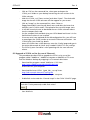
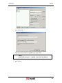
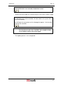
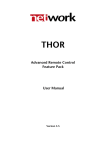
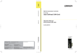
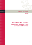
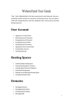
GYDA-SC
System Controller for flashlink®
Product Manual
Rev. 4
GYDA-SC
Rev. 4
Network Electronics ASA
Thorøya
P.O. Box 1020
Sandefjord, Norway
Phone: +47 33 48 99 99
Fax: +47 33 48 99 98
E-mail: [email protected]
www.network-electronics.com
Service Phone: +47 90 60 99 99
Revision history
Current revision of this document is the uppermost in the table below.
Revision Replaces
4
3
3
2
2
1
1
0
0
B
A
B
A
-
Date
Change description
19/12/05 NBS: Corrected Ethernet specification to half duplex.
12/05/05 NBS: Updated setup procedure + new layout.
AR: Info regarding icon for passive modules, new
21/05/04
procedure for update of sw.
AR: Added info regarding home tab & password
05/06/03
protection.
14/05/03 RS: Initial Revision; First official release.
14/04/03 RS: Added new info on GYDA interface.
09/03/03 RS: Preliminary Revision
2
GYDA-SC
Rev. 4
Contents
Revision history............................................................................... 2
1 Product overview......................................................................... 5
2 Specifications .............................................................................. 6
2.1 System.........................................................................................................6
2.2 Ethernet Port ...............................................................................................6
2.3 Web interface ..............................................................................................6
2.4 SNMP interface............................................................................................6
2.5 TCP/IP stack ................................................................................................6
2.6 Serial ports ..................................................................................................6
2.7 Number of cards monitored ........................................................................6
2.8 GPI inputs....................................................................................................6
2.9 GPI outputs .................................................................................................6
2.10 Connector module ....................................................................................7
3 Configuration .............................................................................. 8
3.1 Address setting on each sub-rack.................................................................8
3.2 Jumper settings ...........................................................................................9
4 Connections .............................................................................. 10
4.1 Connecting several sub-racks together ......................................................10
4.2 GPI connections ........................................................................................11
4.2.1 GYDA-SC GPI pinning
11
5 Connecting GYDA to your local area network ............................ 12
5.1 Ethernet connection ..................................................................................12
5.2 Assigning an IP address to GYDA ...............................................................12
6 GYDA Status Monitoring and external alarms ............................ 14
6.1 GPI I/O ......................................................................................................14
6.2 Front Panel - Module Status Monitoring ....................................................14
7 GYDA web interface .................................................................. 15
7.1 General......................................................................................................15
7.2 GYDA web interface – screen navigation ...................................................16
7.3 Home tab ..................................................................................................17
7.4 Password protection ..................................................................................18
7.5 Icon and labels for passive modules. ..........................................................19
8 GYDA – Simple Network Management Protocol interface ......... 21
8.1 SNMP setup ..............................................................................................21
8.2 Audible alarms...........................................................................................21
9 GYDA software upgrade ............................................................ 22
9.1 Upgrade of GYDA sw by use of PCMIA adapter .........................................22
3
GYDA-SC
Rev. 4
9.1.1 Tools needed
22
9.1.2 Procedure
22
9.2 Upgrade of GYDA sw live (by use of Ethernet). ..........................................23
®
General environmental requirements for flashlink equipment ...... 28
Certificate of Conformity .............................................................. 29
Product Warranty ......................................................................... 30
4
GYDA-SC
Rev. 4
1 Product overview
The GYDA System Controller is an advanced control and monitoring card for
®
®
the flashlink system. The card occupies a single slot in a flashlink frame and
can control and monitor up to 8 flashlink frames, each with up to 10 flashlink
modules, a total of 79 modules.
The controller connects to a standard 10BaseT twisted pair Ethernet with
TCP/IP protocol. The user uses a standard web browser to configure and
monitor the flashlink system (i.e. no special software
is needed on the PC, any PC with a web browser will do). All relevant manuals
are also available via the web interface in adobe PDF format.
For users with large heterogeneous systems, the controller supports SNMP
(Simple Network Management Protocol), a generic TCP/IP based protocol for
management of a wide variety of devices. The controller software is located on
a removable compact flash card (the same card type frequently used on
digital cam-eras), and can be easily upgraded by copying new files to the flash
card. New software can be downloaded from our web site.
The controller module has four GPI inputs and a GPI open collector output.
The output is a “catch all” error output. The inputs are general purpose,
intended for monitoring external equipment like battery backup systems,
®
climate control and power supplies. Note that all flashlink power supplies
have GPI outputs, which can be used as inputs to the controller.
5
GYDA-SC
Rev. 4
2 Specifications
2.1 System
Type:
CPU:
Memory:
Operating system:
Intel 80486 compatible.
100MHz.
32MB
Linux ver. 2.2.x.
2.2 Ethernet Port
Type:
Connector:
10BaseT, IEEE802.3, half duplex.
RJ-45, 100 W, UTP cable, EIA/TIA category 3 or better.
2.3 Web interface
-
HTTP version 1.1, HTML ver 4.01 Compatible with all major browsers.
2.4 SNMP interface
-
SNMP ver 1.0 over UDP over IP, following SMI version 2.0 according to relevant
RFC’s.
User defined community string.
User defined traps.
2.5 TCP/IP stack
Version:
V4.
Static IP address selection: Yes, by editing a configuration file on the compact flash
card.
2.6 Serial ports
-
1 x RS422 or RS485 internal to the flashlink frame, available on the power supply
backplane.
1 x RS422/RS485 to external equipment. (Not in use).
1 x RS232 to external equipment. Service use only.
2.7 Number of cards monitored
-
®
79 flashlink cards maximum.
2.8 GPI inputs
Number of inputs:
Pull-up resistors:
Trigger voltage:
4.
Internal 4.7kOhm resistor connected to +5V.
2.5V ±0.5V.
2.9 GPI outputs
Number of outputs:
1.
6
GYDA-SC
Rev. 4
Maximum voltage:
Maximum current:
50V.
0.25A.
2.10 Connector module
If the module is not purchased pre-mounted in a frame, you may find details
of how the connector module is mounted in the user manual for the frame,
FR-2RU-10-2.
The user manual for the frame is also available from our web site:
http://www.network-electronics.com/.
Figure 1: Example of fully equipped flashlink sub-rack.
The communication protocol is found in the user manual for the frame –
FR-2RU-10-2.
7
GYDA-SC
Rev. 4
3 Configuration
Each card has a unique identifier called card position, which is assigned
(trough hardware pinning) automatically when a card is inserted into a frame.
The card positions are numbered from 1 to 10 from a user point of view. From
a protocol (or software) point of view, the cards are addressed 0-9, but the
user should always see positions 1-10 in menus, etc.
Each frame (if you use more than one) should have a unique frame id,
numbered 0-7 (user and protocol/software wise).
3.1 Address setting on each sub-rack
Figure 2 shows the power connections of the frame as well as the RS-422
connections and the DIP-switches for address setting of the frame.
Figure 2: Connector module for the power supply.
Each sub-rack can be assigned an address through the DIP-switches on the
rear. Maximum 8 sub-rack addresses are available.
This address setting only applies when the sub-rack is used in combination
with a GYDA-SC Rack System Controller.
If you have more than 8 sub-racks together, you need several GYDA-SC Rack
System Controller cards.
Note!
In order to ensure proper operation of the system, it is
important that no sub-racks controlled by the same
GYDA-SC Rack System Controller card have the same
address set.
Reset the sub-rack after reconfiguring the sub-rack system,
by turning the power off and on again.
Remember to terminate the last frame with a 110Ω resistor.
8
GYDA-SC
Rev. 4
The setting of the address of a sub-rack is as follows:
1
0
Figure 3: Sub-rack address switch.
0 means switch to the right (OFF)
1 means switch to the left (ON)
SW 4
OFF
OFF
SW 2
OFF
OFF
Address
0
1
ON
SW 1
OFF
ON
OFF
OFF
OFF
ON
OFF
3
ON
ON
OFF
ON
OFF
ON
ON
ON
OFF
6
ON
ON
ON
7
2
4
5
Default address is 0.
The GYDA-SC Rack System Controller automatically detects the position of the
cards within each sub-rack.
3.2 Jumper settings
There are 8 jumpers on the GYDA-SC card:
Position #
Function
1
Boot the system according to
(or no jumpers at all) parameters stored on the flash card.
Force ping boot, this is useful if you
need to change the IP address, and
2
you can’t reach the board on its old
IP address.
3
Not in use; leave unconnected.
Use the static IP address stored on the
4
board.
5-8
Not in use; leave unconnected.
Figure 4: GPI pin-out.
9
GYDA-SC
Rev. 4
4 Connections
4.1 Connecting several sub-racks together
Several sub-racks can be connected to each other through the RS-422 ports
on the rear of each sub-rack.
One GYDA-SC controller can control maximum 8 sub-racks.
You start with the sub-rack containing the GYDA-SC Rack System Controller,
and use 1 RS-422 port to loop through to the next.
The last sub-rack connected must be terminated with 110Ω in order to ensure
proper operation. The other port of the rack containing the GYDA-SC
controller must be left open, and cannot be connected to other sub-racks.
Figure 5 shows an example of how to connect 8 sub-racks together as seen
from the rear end. By using the RS-422 interface at the GYDA-SC controller
card, we control 8 sub-racks via one RS-422 bus.
Figure 5: Control of 8 sub-racks with GYDA-SC.
The 110Ω termination plug used is a standard RJ45 plug with the following
internal wiring:
1236
Figure 6: RS-422 termination.
In the figure above, Pin 1 is connected to Pin 2 with a 110Ω resistor, and Pin 3
is connected to Pin 6 with a 110Ω resistor.
10
GYDA-SC
Rev. 4
4.2 GPI connections
The output can be used for wiring up alarms for third party control systems.
The GPI outputs are open collector outputs, sinking to ground when an alarm
is triggered. The GPI connector is shown in figure 7.
The GPI output will be active, if one or more alarms are active in the system.
This means that each GYDA System Controller can monitor the status of e.g. 4
different power supplies. To monitor more than 4 external devices, these must
be hardwired together as AND logic.
4.2.1 GYDA-SC GPI pinning
Pin #
1
2
3
4
5
6
7
8
Signal
GPI 1
GPI 2
GPI 3
GPI 4
Status
Name
External alarm 1.
External alarm 2.
External alarm 3.
External alarm 4.
General error status for the
system.
Not in use.
+5V
+5V pin
Ground 0V / GND pin.
Mode
Input
Input
Input
Input
Open
Collector
+5V
0V
Figure 7: GPI pin-out.
11
GYDA-SC
Rev. 4
5 Connecting GYDA to your local area network
Follow this guide to quickly install your GYDA controller to an Ethernet
network.
This quick guide assumes that you already have a computer connected to your
LAN and have TCP/IP running on that computer. If you are unfamiliar with
TCP/IP, it could be a good help to have assistance from your system administrator
while doing this.
5.1 Ethernet connection
The GYDA System Controller has a 10Base-T connection on RJ-45. This can be
connected to your local area network devices like a switch or a hub with
unshielded twisted pair cable of type cat 3 or higher.
To access the GYDA System Controller directly from a laptop PC you can use a
crossover cable.
5.2 Assigning an IP address to GYDA
Step 1:
Get an IP address for your unit. Your network administrator normally assigns
this. Remember that the IP address must be unique on your LAN. If you use
the same IP address as another device or machine on your network, you will
cause network problems for you and other users of the LAN. Please make sure
that you use a unique IP address.
Write down the IP address here:
The IP Address for the controller is:
Step 2:
Write down the controller MAC address (also called an "Ethernet address" or a
"hardware address") on the controller card. This is printed below the Compact
Flash Card on the GYDA controller, or on a printed sticker on the backside of
the controller.
A typical MAC address looks like: "00-01-C0-00-21-35"
A MAC address can contain the numbers (0-9) and the letters A to F.
Note that the MAC Address can never contain the letter O, only the number 0
(zero).
Write down the MAC address here:
The MAC Address for the controller is:
12
GYDA-SC
Rev. 4
Step 3:
Find a machine on the network that has Windows NT/95/98/W2K/XP or Unix
(Linux) installed. Start a command shell (DOS prompt) and type in (You may
have to be logged in as "Administrator" on your machine if you run Windows
NT, or "root" on Unix):
arp -s <ip_address> <mac_address> [ENTER]
ping -t <ip_address> [ENTER] (the -t option is only used on Windows)
The mac address separator is '-' (hyphen) under Windows and ':' (colon) under
Unix or Linux.
Let the ping command run…
Example, setting IP address to 10.10.10.199
arp -s 10.10.10.199 00-01-C0-00-21-35
ping -t 10.10.10.199
Step 4:
Connect the controller to the network, and turn the unit on. Wait until the
unit has booted (typ. 30 sec).
You should see that the ping command is starting to get replies, similar to the
sequence below:
64 bytes from 10.10.10.199: icmp_seq=0 ttl=255 time=1.205 msec
64 bytes from 10.10.10.199: icmp_seq=1 ttl=255 time=1.048 msec
...
Press Ctrl-C to stop the ping command.
Step 5:
Start your web browser. Type in the URL: http://ip_address/ (e.g.
http://10.10.10.199/), and you should see the GYDA start page.
- Go to the CONFIG tab, press IP address setup and log in as described in
Chapter 7.4. When you are granted access, select “STATIC IP ADDRESS”,
and set the IP address and other relevant parameters and press "Change IP
settings".
-
Go to the CONFIG tab again, press General setup and press “Restart
system”. You will loose the connection with the controller for ~60 sec,
while the unit is restarting with the static IP settings.
“Step 6”:
Congratulations, you have now successfully connected the GYDA controller to
your LAN.
13
GYDA-SC
Rev. 4
6 GYDA Status Monitoring and external alarms
6.1 GPI I/O
The output can be used for wiring up alarms for third party control systems.
The GPI outputs are open collector outputs, sinking to ground when an alarm
is triggered. The GPI connector is described in Chapter 4.2.1.
The GPI output will be active, if one or more alarms are active in the system.
This means that each GYDA System Controller can monitor the status of e.g. 4
different power supplies. To monitor more than 4 external devices, these must
be hardwired together as AND logic.
6.2 Front Panel - Module Status Monitoring
The status of the module can be easily monitored visually by the LEDs at the
front of the module. The LEDs are visible through the front panel as shown in
the figure hereunder.
Figure 8: The LEDs of GYDA-SC (text not printed on the front panel)
The GYDA-SC has 4 LEDs each showing a status corresponding to the GPI
pinning. The position of the different LEDs is shown in the figure above.
Diode
Red LED
Status
Module is faulty
IP address
No IP address
2
assigned
Disk access
Traffic
1
2
1
Green LED
Module is OK
Module power is OK
No LED
Module has no power
IP address assigned
Accessing disc
Traffic on Ethernet port
Not accessing disc
No traffic on Ethernet port
LED will be red for a short time during power-up.
The green LED will flash for about 30 seconds during the boot process of theGYDA-SC.
14
GYDA-SC
Rev. 4
7 GYDA web interface
7.1 General
GYDA System Controller can control and monitor up to 79 modules, in a total
of 8 frames. Each frame must be configured with a unique frame address, set
by DIP switches at the rear of the frame, as described in Chapter 3.1 of this
®
manual and in the user manual for the flashlink frame, FR-2RU-10-2.
Interconnection of several frames is also described in the user manual for the
frame itself, as well as in Chapter 4.1 of this manual.
There are six different + one optional views in the GYDA System Controller
web interface. Each has its own menu-tab at the top, and will be highlighted
when selected.
- HOME (Optional, see Chapter 7.3)
- SYSTEM (An overview of the system connected to GYDA)
- ALARMS (All alarms within the system.)
- LOG (All events after power up of the GYDA System Controller)
- CONFIG (TCP/IP and SNMP Configuration Settings)
- MANUALS (All user manuals in PDF-format)
- ABOUT
Figure 9: The menu-tabs of the GYDA web interface.
GYDA-SC has two different pages for each module (found under the
“SYSTEM” tab).
Module Information Page
Module Configuration Page
Open user manual
Figure 10: The icons for the different views in the "System" menu.
®
Each of the different modules in the modular flashlink range has a dedicated
icon, which will appear in the corresponding position of the frame.
The default user name and password for access to the sub menus under the
CONFIG tab is described in Chapter 7.4.
15
GYDA-SC
Rev. 4
7.2 GYDA web interface – screen navigation
The web interface with the information view of the GYDA System Controller is
shown in figure 11. To the left we see the detection and indication of the 1-8
frames that are connected to the system. In this case frame 0 is selected of the
3 frames that are connected to GYDA. On the frame itself, we see the
indication of the active card as a grey frame on the red front. By clicking the
different positions or icons of the frame, the different card modules can be
controlled.
Frame
inicator
Card indicator
Figure 11: Information view of the GYDA System Controller.
Figure 12: The icon for the GYDA System Controller.
As shown in figure 11, we can get a summary of the alarms in the system.
Each alarm can be in one of three different states:
- Active (Red colour). An alarm is present in the system, and is not
acknowledged.
- Acknowledged (Yellow colour). A present alarm that has been
acknowledged.
The alarm will disappear from the list as soon as the condition that set the
alarm no longer exists.
- Restored (Green colour). The condition that set the alarm does no longer
exist. The alarm must be acknowledged in order to disappear from the list.
The status for the GPI inputs of the GYDA System Controller is shown below
the alarm list. The status can be either active (triggered by an external device)
or inactive.
16
GYDA-SC
Rev. 4
The GPI output can also be in one of two states. The GPI output is a catch all
GPI output. If one or more alarms are active in the system, the GPI output will
be active, whereas if all alarms are either acknowledged, restored or there are
no alarms in the system, it will be inactive.
The CONFIG screen of the GYDA System Controller has settings for how
GYDA shall work.
- Search for new cards
Useful if the system configuration changes frequently.
This setting means that all 79 possible addresses are polled each time in
order to search for new modules.
- Collect info from known cards
Default setting, this setting is useful if the system doesn't change
frequently.
This setting will poll the status of known cards and one new empty slot at
a time. New cards will be detected at a rate determined by the number of
cards in the system, the more empty slots the longer it will take to detect
new modules. On the other hand, all cards are now polled once per
second so changes on the known modules will be reported much faster
than before.
Single scan of empty slots
Will scan all empty slots for new modules. Setting is only available when
the 'Collect info from known cards' is chosen. Useful to speed up the
detection of new modules. Will not affect the scanning mode of GYDA.
7.3 Home tab
Generic webserver for static html can now be enabled from the CONFIG
page, under "General setup". This will change the graphics on the tab-menu
(might need a forced reload of the browser to see it properly). This homepage
can also be set as start page if this is needed.
Figure 13. Home tab configuration
Figure 14. Home tab enabled
The static pages can be put on the CF (Compact flash) card in the directory
called "home". To access the “home” directory, you need to remove the
flashcard from the GYDA module and put into a PCMCIA/USB adapter for CF.
The file structure of the CF is shown in figure 15.
Note!
Make sure that you don’t modify files outside the “home”
directory; this may STOP GYDA from working.
17
GYDA-SC
Rev. 4
Figure 15. File structure of the CF
Note!
Make sure URLs are relative, or reference files on other WEB
servers. References to c:\\xxxxx or similar will not work.
7.4 Password protection
The built-in password protection uses the htpasswd mechanism of the Apache
web-server. In the default setup, GYDA allows anonymous / open access to
the card information Two extra levels of protection (observer and operator)
can be enabled for situations where anonymous access to the system-, alarmand log tabs are not wanted.
To enable “Strict password protection”, go to the CONFIG tab, select User
and access administration.
Figure 16. Default setup of User and access administration.
18
GYDA-SC
Rev. 4
The three access levels are defined as follows:
- Observer
Read only account, can’t acknowledge alarms and re-configure modules.
- Operator
Has access to acknowledging alarms and re-configuring modules.
- Administrator
Access to the CONFIG tab.
The levels are not inclusive, so a normal user account needs both observer and
operator access. The default admin account does not have observer and
operator access for security reasons. There is no limit to the number of users.
Note!
In factory setting, all passwords are: password with user
names as shown in figure 16.
Note!
Remember to change the admin password to prevent abuse
of GYDA.
7.5 Icon and labels for passive modules.
Passive optical modules like: WDM, CWDM, DWM and WOC don’t contain
any microcontroller which makes them able to communicate with GYDA.
However, through GYDA it’s possible to assign a graphical icon and a label for
the module to make it visible in the GYDA user interface. The procedure is as
follows:
- Click on the slot were the passive optical device is installed.
-
Press the “Tool” button below the frame.
-
Select the type of module from the “Card type” pull down menu.
-
If needed give the module a name in the “Card label” box.
Press Apply.
The graphical icon and the name of the module will appear when
returning to the SYSTEM tab, as shown in figure 17.
19
GYDA-SC
Rev. 4
Figure 17. Graphical icon for passive optical modules.
20
GYDA-SC
Rev. 4
8 GYDA – Simple Network Management Protocol interface
®
GYDA can be used as an SNMP agent. This means that all the flashlink
modules can be configured and monitored through a higher level third-party
management system.
8.1 SNMP setup
Setup is done through the web interface of GYDA (described in Chapter 7).
This is found under the CONFIG tab.
The following parameters must be set:
- sysContact
Contact person and contact details for the service person.
- sysLocation
Where is the system located.
- SNMP community
3
Password to access the GYDA SNMP agent .
- SNMP trap destination
IP-address of the SNMP manager.
- SNMP trap community
3
Password to access the SNMP manager .
8.2 Audible alarms
Using SNMP is the easiest way to implement audible alarms from GYDA to the
operator’s computer.
All alarms will generate SNMP traps that are fed to the operator’s computer as
configured in Chapter 8.1.
3
Corresponding community setup must be done at the SNMP manager.
21
GYDA-SC
Rev. 4
9 GYDA software upgrade
GYDA System Controller shall automatically detect all modules that are part of
®
the modular flashlink product ranges. As the product ranges are expanded
with additional modules, a new release of the GYDA software is made in order
to detect and monitor the new modules.
There are two procedures available for update of GYDA sw, one by use of
PCMIA adapter, and one for updating the GYDA sw live (Ethernet update).
9.1 Upgrade of GYDA sw by use of PCMIA adapter
This chapter describes how to upgrade the software on your GYDA System
Controller by downloading the new software version from our WEB page. You
can either follow the procedure below in order to replace the software on the
compact flash card on the controller itself, or you can upload the new
software version to another compact flash card and replace the card on the
controller with the new one.
9.1.1 Tools needed
-
Laptop or standalone PC with PCMCIA interface
PCMCIA adapter
Undisker software, can be downloaded here: http://www.undisker.com/.
9.1.2 Procedure
-
Access the GYDA from a web browser, go into the CONFIG page and
write down or print all network & SNMP (only needed if SNMP is in use)
settings.
-
Create 2 new folders on your desktop, e.g. “GYDA_new” and “old_GYDA”.
Download the latest GYDA software version from:
ftp://ftp.network-electronics.com/flashlink/gyda/
This is a compressed zip file archive containing a complete disk image of
the latest GYDA software release.
-
Extract this zip file into the “GYDA_new” folder.
Remove the compact flash card from the GYDA module and insert it into
the PCMCIA adapter.
Put the PCMCIA adapter into your computer.
Start the program Undisker.
Creating a back up of the old GYDA software:
-
Click on “Image” on the command line, select “Capture Floppy/
-
Removable” from the pull down menu.
Select the letter that indicates your PCMCIA station.
-
Type in the filename, i.e. “old_GYDA”. Make sure that the format is Generic
Disk Image (IMG) in the “Save as type” dialog box.
-
Save the file in the folder, which you named “old_GYDA” on your desktop.
Upload new GYDA software to the compact flash card:
22
GYDA-SC
-
Rev. 4
Click on “File” on the command line, select open and open the
“GYDA_new” folder on your desktop containing the new version of the
GYDA software.
-
Mark the “GYDA_x.xx” [latest version] and select “Open”. The whole disk
image for the new GYDA software will then appear on your screen.
-
Click on “Image” on the command line, select “Write to
-
-
Floppy/Removable” from the pull down menu and select the letter that
indicates your PCMCIA station. The upload of the new disk image starts.
It will take several minutes to download the new GYDA software release
into the compact flash card.
Put the compact flash card back into your GYDA board and insert it in the
flashlink frame where it was installed.
Since new ones have replaced all the old configuration files, you will have
to reconfigure the GYDA in order to restore the Ethernet connection. See
“GYDA Quick Start Guide” for details.
Access the GYDA from a WEB browser; enter the 'Config' page and type in
the entire old network & SNMP (only needed if SNMP is in use) settings.
The GYDA System Controller is now operating with the new software
release.
9.2 Upgrade of GYDA sw live (by use of Ethernet).
This procedure describes how to upgrade the GYDA s.w by use of the
program called “WebDrive”. WebDrive integrates a WebDAV or FTP server
into the Windows desktop by mapping it to a network drive letter.
-
Download the program named “WebDrive v5.32” from:
http://www.webdrive.com/download/index.html
and install it on your computer.
-
Download the latest GYDA: “gyda_files_x.xx.zip” from:
http://labs.network-electronics.com/gyda/
and extract the files to a local folder on your computer.
-
Enable flash write under the “General Setup” in the GYDA “CONFIG” page.
Software update
Flash disk is write protected, enable flash writes?
Enable
-
Start WebDrive:
23
GYDA-SC
Rev. 4
-
Press “New Site”
-
Type in a name and the http address for your GYDA
Note!
Remember to type in “/upload” after the http address.
-
Press “Finish”
24
GYDA-SC
-
Rev. 4
Select “WebDAV” as Server Type.
Do as follows when upgrading from GYDA versions older than 1.07:
-
Use “Anonymous” logon.
-
Press “Connect”.
Do as follows when upgrading from GYDA 1.07 or newer:
-
Remove the hook from the “Anonymous/Public Logon” selection.
-
Type in the “Username” & “Password” for your GYDA.
You must have admin rights in order to do this. See Chapter 7.4 for correct
login.
-
Press “Connect”
GYDA will now appear as a standard drive on your computer.
25
GYDA-SC
Rev. 4
This is the complete image of the flash disk
on your GYDA card.
-
Replace/ add the following files and folders which you have downloaded
from our http://labs.network-electronics.com/gyda/ :
- cards
This folder must only be added if it doesn’t exist in the version you are
upgrading from.
- home
This folder must only be added if it doesn’t exist in the version you are
upgrading from.
- manuals
Delete this folder and copy over the new one.
- htgroup
This file must only be added if it don’t exist in the version you are
upgrading from.
- htpasswd
This file must only be added if it don’t exist in the version you are
upgrading from.
- root
Replace this file with the new one.
- zImage
Replace this file with the new one.
Note!
Do not try to access any of the other files and folders on
your GYDA drive. Doing so might lead to loss of
communication with the GYDA drive.
-
Disable the flash write under the “General Setup” in the GYDA “CONFIG”
page.
26
GYDA-SC
Rev. 4
Software update
Warning! flash disk is now writeable, disable flash writes?
Disable
-
Restart the GYDA under the “General Setup” in the GYDA “CONFIG” page.
Restart system controller
This will restart this system controller. All other cards in the system will
run uninterruptedly.
You will loose the connection to this web page for approx. 1 minute after
restarting the controller.
Restart
Note!
You may have to press the “SYSTEM” tab a couple of times
to re-establish contact with GYDA again.
-
The update process is now completed!
27
GYDA-SC
Rev. 4
®
General environmental requirements for flashlink equipment
1. The equipment will meet the guaranteed performance specification under the
following environmental conditions:
- Operating room temperature range:
0°C to 50°C
- Operating relative humidity range:
< 90% (non-condensing)
2. The equipment will operate without damage under the following environmental
conditions:
- Temperature range:
-10°C to 55°C
- Relative humidity range:
< 95% (non-condensing)
3. Electromagnetic compatibility conditions:
- Emissions:
EN 55103-1 (Directive 89/336/EEC)
- Immunity:
EN 55103-2 (Directive 89/336/EEC)
28
GYDA-SC
Rev. 4
Certificate of Conformity
Network Electronics ASA
N-3204 Sandefjord
Norway
Company Registration Number:
NO 976 584 201 MVA
Declares under sole responsibility that the product:
Product Name:
GYDA-SC
Product Description:
flashlink System Controller
®
To which this declaration relates are of Norwegian origin and are in conformity with
the following standards:
EN 55103-1: 1996
Generic Emissions Standard
EN 55103-2: 1996
Generic Immunity Standard
29
GYDA-SC
Rev. 4
Product Warranty
The warranty terms and conditions for the GYDA-SC follow the General Sales
Conditions by Network Electronics ASA. These conditions are available on the
company web site of Network Electronics ASA:
www.network-electronics.com
30