1
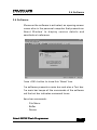
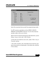
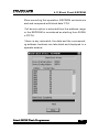
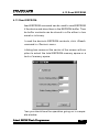
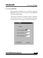
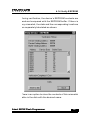
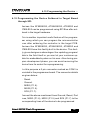
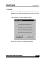
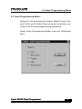
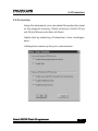
Topview Programmer
User Manual
Atmel 89CXX Flash Programmer
75
Contents
Chapter 1 - Introduction
1.1 Welcome ........................................................................ 1
1.2 Hardware ........................................................................ 3
1.3 For Technical or Customer Support ................................. 5
1.4 Packaging .......................................................................6
Chapter 2 - Getting Started
2.1 System Requirements .................................................... 7
2.2 Installing Software ...........................................................8
2.3 Installing Hardware .......................................................... 9
2.4 Software ........................................................................ 10
2.5 Uninstalling Software ..................................................... 12
Chapter 3 - Buffer Operations
3.1 Flash/ EEPROM Buffer ................................................. 13
3.2 Flash Buffer
3.2.1 Load Flash Buffer ............................................... 15
3.2.1 Load Flash Buffer ............................................... 16
3.2.2 Save Flash Buffer ............................................... 17
3.2.3 Edit Flash Buffer ................................................ 19
3.2.3 Edit Flash Buffer ................................................ 20
3.2.4 Locate Flash Buffer ............................................ 21
3.2.5. Clear Flash Buffer .............................................. 22
3.2.6 Fill Flash Buffer .................................................. 23
3.2.7 Copy Flash Buffer .............................................. 24
3.2.8 Check sum Flash Buffer ..................................... 25
3.2.9 Flash Buffer - Disassembly ................................ 26
Atmel 89CXX Flash Programmer
77
3.2.10 Flash Buffer - Enter Program .............................. 28
3.3 - EEPROM Buffer ............................................................. 30
3.3.1 Load EEPROM Buffer ........................................ 31
3.3.2 Save EEPROM Buffer ........................................ 33
3.3.3 Edit EEPROM Buffer ......................................... 35
3.3.4 Locate EEPROM Buffer ..................................... 36
3.3.5 Clear EEPROM Buffer ........................................ 37
3.3.6 Fill EEPROM Buffer ........................................... 38
3.3.7 Copy EEPROM Buffer ........................................ 39
3.3.8 Checksum EEPROM Buffer ............................... 40
Chapter 4 - Device Operations
4.1 Device Selection ........................................................... 41
4.2 Auto Programming Mode .............................................. 43
4.4 Blank Check Device ...................................................... 46
4.5 Program Device ............................................................. 48
4.6 Read Device .................................................................. 51
4.7 Verify Device ................................................................. 53
4.8 Protect Device .............................................................. 55
4.9 Enable Serial Program .................................................. 57
4.10 Disable Serial Program ................................................. 58
4.11 Blank Check EEPROM ................................................. 59
4.12 Program EEPROM ....................................................... 61
4.13 Read EEPROM ............................................................. 63
4.14 Verify EEPROM ............................................................ 64
4.15 Programming the Device Soldered in Target Board
through SPI ................................................................... 66
Atmel 89CXX Flash Programmer
8
Chapter 5 - Setting
5.1 Serial Port Setting ......................................................... 6 8
5.2 Options ......................................................................... 6 9
5.3 Auto Programming Mode .............................................. 70
5.4 Protection ..................................................................... 71
Atmel 89CXX Flash Programmer
79
1.1 Welcome
Chapter 1 - Introduction:
1.1 Welcome:
Thankyou for purchasing Topview Programmer.
The Device Programmer is meant for programming all
the Atmel’s 89CXX Family devices using any standard
personal computer. In fact, the programmer is an external addon card that can be connected to the host computer at the serial port..
The programmer supports entire family of Atmel’s 89CXX
devices:
·
·
·
·
·
·
·
AT89C1051
AT89C2051
AT89C4051
AT89C51
AT89LV51
AT89C52
AT89LV52
·
·
·
·
·
·
AT89S53
AT89LS53
AT89C55
AT89LV55
AT89S8252
AT89LS8252
Atmel 89CXX Flash Programmer
1
1.1 Welcome
Programming Operations:
The programmer maintains a separate buffer area for the
device’s flash memory and also for EEPROM memory
(in 89S8252) space in the personal computer. Initially
the programming data (Hex/Binary Files) has to be loaded
into this buffer area and then transferred into the device.
When the buffer holds the relevant data, using proper
commands, the data can be manipulated, disassembled
and then also be viewed as the assembly program.
The programmer also supports programming the flash
memory space using SPI bus in devices, 89S8252,
89LS8252, 89S53 and 89LS53. For this purpose, a separate 5 pin connector is provided onboard. Using this facility, the flash memory area of the device can be programmed using SPI bus even after the device has been
soldered in the target hardware.
Atmel 89CXX Flash Programmer
2
1.2 Hardware
1.2 Hardware:
The Programmer consists of a board, a separate power supply
unit and a serial port cable.
The power supply provides a set of DC voltages like 9V, 500mA
and 18V, 100mA . The programmer board has on board regulators
for generating 5V and 12V required for the normal operation and
programming purposes.
The Programmer board sports a single 40 pin ZIF socket for programming both 40 and 20 pin devices.
A DIN connector marked as ‘POWER’ is used for connecting the
power supply unit to the programmer board The terminations of
the connector is given below:
· Pin 1 & 2 - 9V
· Pin 3 & 4 - Ground
· Pin 6 & 7 - 18V
Similarly the connecter named as ‘SERIAL PORT’ helps to connect the host computer to the programmer board. The serial port
connector details are given below:
·
·
·
·
·
·
·
Pin 1 - NC
Pin 2 - RXD
Pin 3 - TXD
Pin 4 - NC
Pin 5 - Ground
Pin 6 - NC
Pin 7 - NC
Atmel 89CXX Flash Programmer
3
1.2 Hardware
· Pin 8 - NC
· Pin 9 - NC
A switch marked as ‘RESET’ is used for resetting the programmer.
A 5 pin connector with the name ‘CON3’ is used to connect the
target board for programming through SPI. For more details refer
to the topic Programming the device Soldered in the Target
board.
Atmel 89CXX Flash Programmer
4
1.3 For Technical or Customer...
1.3 For Technical or Customer Support:
You can reach Frontline Electronics Pvt Ltd for the technical support and application assistance in the following
ways:
Email questions to [email protected]
Send questions by mail to:
Frontline Electronics Pvt Ltd,
1/255C - Thatha Gounder St,
Kumaran Nagar, Alagapuram,
Salem - 636 016.
India.
Phone : 0427 449238/431312.
Fax
: 0427 449010.
For additional information and etc, please refer our
website, www.Frontline-Electronics.com
Atmel 89CXX Flash Programmer
5
1.4 Packaging
1.4 Packaging:
Your package contains the following:
1.
2.
3.
4.
5.
Programmer board.
Power supply unit.
Serial port cable.
User Manual.
CD Containing software.
Atmel 89CXX Flash Programmer
6
2.1 System Requirements
Chapter 2 - Getting Started.
2.1 System Requirements:
The minimum requirements are as follows:
·
·
·
·
Personal Computer with Windows 95 or above.
A serial port.
Free hard disk space of 2MB.
Internet Explorer of version 4.0 or above.
Atmel 89CXX Flash Programmer
7
2.2 Installing Software
2.2 Installing Software:
Insert the CD supplied with the programmer pack and run the
installer file “Topview Programmer.msi” (This is a windows installer program, which installs all the files in the directory selected by the user) found in the Folder <Topview Programmer>. You may select the destination directory during installation.
The installer package will guide you through the installation
process.
Atmel 89CXX Flash Programmer
8
2.3 Installing Hardware
2.3 Installing Hardware:
Connect the power supply unit to the programmer board using
the 9 pin DIN connector(CON1) marked as ‘POWER’.
Connect the programmer to the host computer using serial
port cable.
Switch on the power supply to the programmer board.
Execute the application (Atmel Flash Programmer) from the
Start -> Programs menu. An opening screen comes up with
an ‘About’ dialog box. If the PC is not able to establish communication via serial port (COM2 - default), it will give an error
message “Cannot establish communication”. This indicates
that the assigned COM port is not available for this application.
At this juncture select the <settings> option and use serial
port settings to change the COM port to establish communication. If the selected COM port is free, the communication is
established and the device programming can be started.
Atmel 89CXX Flash Programmer
9
2.4 Software
2.4 Software:
Whenever the software is activated, an opening screen
comes alive in the personal computer that presents an
‘About Window’ to display version details and
manufacture’s reference.
Press <OK> button to close this ‘About’ box.
The software presents a main bar and also a Tool bar.
The main bar keeps all the commands of the software
and the tool bar indicates command Icons.
Menu bar commands:
· File Menu.
· Buffer.
· Device.
Atmel 89CXX Flash Programmer
10
2.4 Software
· Settings.
· Help.
Like any other Win 95 software, when the cursor is placed
over the menu, the relevant explanation is displayed in
the status bar of the Window. The status bar also gives
appropriate messages when any operation is carried out.
The status bar gives details of current selected device,
COM port status, mode operation and also the status of
the selected protection mode of the device. These details are updated each time when there is a change in
the selection.
Atmel 89CXX Flash Programmer
11
2.5 Uninstalling Software
2.5 Uninstalling Software:
For uninstalling the software execute the ‘Topview
Programmer.msi’ from the CD found in the folder <Topview
Programmer>.
Select ‘Remove’ option to remove the application from
hard disk.
Atmel 89CXX Flash Programmer
12
3.1 Flash/EEPROM Buffer
Chapter 3 - Buffer Operations:
3.1 Flash/ EEPROM Buffer:
The programming environment sports a buffer space that
plays an important role during programming. Normally,
the buffer space will be made equal to the size of the
selected device’s flash area.
For an example, for the device, AT89C51 the buffer space
goes up to 4K (0FFFH). If the target file exceeds this
space (for that device), an error message will be duly
displayed for your convenience.
During programming, you may want to load your target
program file into this buffer space and then you may
modify/ correct the contents as per your need.
For your convenience, the buffer provides a ‘Single line
Assembler’ to carry out these modifications with ease.
Another utility is, the buffer, helps you keep programming data from many files in order. You can load these
files into the buffer and verify the whole lot and then program the target device in a single shot.
Buffer supports editing (both in hex and ASCII), locating
a byte, Clearing, Filling, Copying operations and also
generates the check sum. All these operations are explained in detail in subsequent pages.
Atmel 89CXX Flash Programmer
13
3.1 Flash/EEPROM Buffer
Another interesting facility is made available using different colors for the buffer contents to indicate certain
operations.
Normally the buffer contents are displayed in the black
color. When a file is loaded into the buffer, the color
changes to blue.
When you carry out editing on contents of the buffer, the
edited portion is displayed in red color. When you load
the buffer from the flash area of the selected device, that
portion is displayed in green.
So with a little experience on the usage of buffer functions, the coloring will assist you very much during program development/ debugging.
The buffer also sports a disassembly facility. When you
activate this, the contents of the buffer will be displayed
as program rather than as data and you can see the
actual program code in mnemonics. At this stage, you
can edit your program code or insert new program lines
using built in single line assembler.
In few of the Atmel’s 89CXX devices an EEPROM is also
present along with the flash memory. Hence, a separate
buffer is made available for this memory.
Just like Flash buffer, this buffer also has all the features except the disassembly facility since it contains
only data.
Atmel 89CXX Flash Programmer
14
3.2.1 Load Flash Buffer
3.2 Flash Buffer:
3.2.1 Load Flash Buffer:
To load a file into the Flash Buffer, click menu, <File>
and then click <Flash Buffer> from <Load File> command.
You can see a dialog box opens up for selecting the
target file. Either a hex/binary file can be loaded. The
buffer size will be equal to the flash memory space of
the selected device.
Select the file name using the load file menu and then
click open.
If the selected file is a binary file, the control will prompt
for the starting address.
Enter the starting address.
The dialog box closes and the file gets loaded into the
buffer. A progress bar indicates the progress of loading.
If the file exceeds the buffer capacity, it is indicated by
an error message as shown below:
Atmel 89CXX Flash Programmer
15
3.2.1 Load Flash Buffer
Otherwise, the details of the file loaded area will be displayed for the Hex file format. The starting and ending
address of the blocks will also be displayed in the dialog box.
For the binary file, a message, “Operation completed successfully “ will be displayed.
Atmel 89CXX Flash Programmer
16
3.2.2 Save Flash Buffer
3.2.2 Save Flash Buffer:
This command is used to save the contents of the flash
buffer in a file in the disk.
To activate this command, click <File> and then <Save
As> and <Flash Buffer>.
You can see a dialog box opens up and prompts you to
enter the starting address and the ending address of the
buffer and also prompts for the type of the file: hex or
binary.
Then click the <Save> button to start the save process.
Now the dialog box waits for the name of the file. Select/
Enter the name and click <Save> button.
Atmel 89CXX Flash Programmer
17
3.2.2 Save Flash Buffer
Another small window opens up and indicates the successful completion of the save operation.
Atmel 89CXX Flash Programmer
18
3.2.3 Edit Flash Buffer
3.2.3 Edit Flash Buffer:
This Edit command is activated as shown below:
The flash Buffer window may open in binary format for
editing/ viewing if the buffer is not opened already. If it is
already opened, then it becomes current active window.
The contents are displayed in both Hex and ASCII format as shown here:
Atmel 89CXX Flash Programmer
19
3.2.3 Edit Flash Buffer
The status bar gives current editing address. You can
use arrow keys, <Page Up> and <Page down> keys to
move the cursor to any position in the screen.
<Home> and <End> keys take you to the first and last
addresses displayed on the screen.
To edit in ASCII part of the display, click your mouse
over any place on the right side of the buffer window. The
current address for that location also gets displayed in
the status bar.
When you change anything in the ASCII side, the corresponding hex code also gets modified in the left side.
The locations you edit are displayed in red color.
When you load the buffer from a file then you can see
the contents in blue color.
When you read the flash content of the target, the same
will be displayed in the buffer window in green color.
When you clear the buffer using <Clear> command, the
contents will become black.
Atmel 89CXX Flash Programmer
20
3.2.4 Locate Flash Buffer
3.2.4 Locate Flash Buffer:
Use this command to set the starting address for the
flash buffer. When you activate this command, a small
dialog box opens up on the screen to get the address.
This <Locate> command can also be activated by double
clicking over the address displayed in the window.
Atmel 89CXX Flash Programmer
21
3.2.5. Clear Flash Buffer
3.2.5. Clear Flash Buffer:
This command can clear the total flash buffer area to
FFH. When you activate this command, you can see all
the contents of the flash buffer getting ‘FFH’ and change
the color to black to indicate the completion of the operation.
Atmel 89CXX Flash Programmer
22
3.2.6 Fill Flash Buffer
3.2.6 Fill Flash Buffer:
You can use this command to fill block of flash buffer
with a fixed data.
When you get into this operation, you should see a dialog coming up to prompt you for Starting, Ending addresses along with the fill data as shown here:
Successful operation is indicated by another window.
Atmel 89CXX Flash Programmer
23
3.2.7 Copy Flash Buffer
3.2.7 Copy Flash Buffer:
This command copies the contents from one block of
data to another area of the flash buffer.
When getting into this operation, a dialog box comes up
to get addresses of Starting, Ending and the Destination.
Successful completion is indicated by another small window.
Atmel 89CXX Flash Programmer
24
3.2.8 Check sum Flash Buffer
3.2.8 Check sum Flash Buffer:
You can get the check sum of the flash buffer giving starting and ending addresses of the buffer.
You need to key in these addresses in the dialog box
that comes up.
The calculated check sum is displayed in another window.
Atmel 89CXX Flash Programmer
25
3.2.9 Flash Buffer - Disassembly
3.2.9 Flash Buffer - Disassembly:
This command is meant for viewing the contents of the
flash buffer as program rather than as data. You can use
this to modify the data at the given address, or change/
modify the program lines.
When you select this command, a window with the name,”
Flash Buffer - Disassembly View” will be opened up and
the contents are displayed as program lines as shown
here:
When you see this window then you can modify any instruction by double clicking over the instruction in the
window.
Now, you should see a dialog box appearing with the
Atmel 89CXX Flash Programmer
26
3.2.9 Flash Buffer - Disassembly
current instruction at that address as shown here:
You can enter a new instruction or change the data or
address and press <Enter > key or click over <Store>
button to record the changes in the buffer.
Note that you cannot change a one-byte instruction into
a two or three byte instruction for obvious reasons. An
error message may indicate this state. A three byte instruction can be converted into 1/2 byte instruction with
NOPs filling up remaining bytes of the instruction.
You can change the address field of the window by double
clicking over that specific location. A small window pops
up to get the correct address.
You can get into any of these commands by right clicking anywhere in the window and then select the required
command from the floating window.
Atmel 89CXX Flash Programmer
27
3.2.10 Flash Buffer - Enter Program
3.2.10 Flash Buffer - Enter Program:
This command is meant for entering your program in mnemonics line by line in the flash buffer. At the end of each
line the instructions are converted into opcodes thanks
to the built-in single line assembler and everything is
recorded in the flash buffer.
When you activate this command, you should see a window prompting you to enter the starting address of the
program.
If the program window is already opened, then the starting address of the program window will be set to the new
value and then the window gets cleared and you can note
a new dialog box coming up at the center to get your
program in mnemonics as shown here:
Atmel 89CXX Flash Programmer
28
3.2.10 Flash Buffer - Enter Program
Enter your program line by line and at the end of each
line press <Enter> key or click over <Store> button to
convert the mnemonics into opcodes and store them in
the flash buffer.
During program entry, for error conditions, a separate
error window displays the nature of the error.
At the end of the program entry, press <Esc>key or click
over <Cancel> button to quit this command.
Atmel 89CXX Flash Programmer
29
3.3 - EEPROM Buffer
3.3 - EEPROM Buffer:
A buffer in PC memory is maintained for programming
on-chip EEPROM available in Atmel devices, AT
89S8252,AT89LS8252. This buffer will be activated only
when these two devices are selected. For all other devices, this buffer will not be activated.
The on-chip EEPROM of capacity 2K bytes can be programmed or verified with the contents of this buffer.
Both hex format and binary format data files can be loaded
into this buffer from the disk. The contents of the buffer
can also be saved in the disk.
The following commands enable you to interact with this
buffer during the device programming operations.
·
·
·
·
·
·
Edit.
Locate.
Clear.
Fill.
Copy.
Check sum.
Atmel 89CXX Flash Programmer
30
3.3.1 Load EEPROM Buffer
3.3.1 Load EEPROM Buffer:
To load a file into EEPROM Buffer, click <File> command and then select <EEPROM Buffer> at <Load File>.
A dialog box comes up to ease the selection.
Select either a hex or binary file. The buffer size will be
automatically equal to the EEPROM size of the selected
device.
Select the file name and click open. If the selected file
is a binary file, then the control prompts for a starting
address.
Enter the starting address.
The dialog box goes off and an indicator shows the progressive file loading.
If the file exceeds the buffer capacity, an error will be
flashed across the monitor as Shown below:
Otherwise, the details of the loaded file will be displayed
Atmel 89CXX Flash Programmer
31
3.3.1 Load EEPROM Buffer
in the hex format.
The starting and ending addresses of the blocks will also
be displayed in the box.
For the binary file format, the message, “Operation completed successfully” will be displayed.
Atmel 89CXX Flash Programmer
32
3.3.2 Save EEPROM Buffer
3.3.2 Save EEPROM Buffer:
This command can be used to save the contents of the
EEPROM Buffer as a file in the disk.
Start clicking <File> and <Save As> and then <EEPROM
Buffer>.
A dialog box opens up to prompt you to enter the starting and the ending addresses of the buffer and also
prompts you to select the file type: hex or binary.
Then you should click <save> button to start the save
process.
Now you need to enter the file name in the dialog box
and click the <Save> button to start the saving operation.
Atmel 89CXX Flash Programmer
33
3.3.2 Save EEPROM Buffer
After completion, you should see the following message
as a mark of successful operation.
Atmel 89CXX Flash Programmer
34
3.3.3 Edit EEPROM Buffer
3.3.3 Edit EEPROM Buffer:
EEPROM Buffer contents can be viewed using this command.
You can see a window coming up indicating the contents of the buffer. You can also see the contents displayed both in binary and ASCII formats. These contents
can also be edited for any modification.
Atmel 89CXX Flash Programmer
35
3.3.4 Locate EEPROM Buffer
3.3.4 Locate EEPROM Buffer:
This command enables you to set the starting address
of the EEPROM window for viewing/editing. This can also
be done by moving the scroll bar at the right side of the
window.
When you activate this command using your tool bar,
you may notice a window popping up asking you for the
starting address.
Key in the required address and complete the window to
get the buffer window with the correct address.
Atmel 89CXX Flash Programmer
36
3.3.5 Clear EEPROM Buffer
3.3.5 Clear EEPROM Buffer:
By using this command, you can clear the contents of
the EEPROM buffer to FFH and the color of the contents
will become black.
Atmel 89CXX Flash Programmer
37
3.3.6 Fill EEPROM Buffer
3.3.6 Fill EEPROM Buffer:
This command is meant for filling a block of memory
space with a fixed data.
When you activate this, you can see a dialog box coming up to prompt you for the Starting, Ending addresses
and also the Fill data as shown below:
Note the color difference in the buffer window.
Atmel 89CXX Flash Programmer
38
3.3.7 Copy EEPROM Buffer
3.3.7 Copy EEPROM Buffer:
This command copies the contents from one block of
data to another area of the EEPROM buffer.
When getting into this operation, a dialog box comes up
to get addresses of Starting, Ending and the Destination.
Successful completion is indicated by another small window.
Atmel 89CXX Flash Programmer
39
3.3.8 Check sum EEPROM Buffer
3.3.8 Check sum EEPROM Buffer:
This command may be used to find out the check sum
of the EEPROM Buffer contents.
When this command is selected, you get a dialog box
prompting for the starting, ending addresses.
Then a separate window comes up giving you the calculated check sum.
Atmel 89CXX Flash Programmer
40
4.1 Device Selection
Chapter 4 - Device Operations:
4.1 Device Selection:
The Atmel Device programmer can program all the devices of 8031 family including both 5V and 12V versions
and using either parallel or SPI mode. The programmer
supports following Atmel devices:
·
·
·
·
·
·
·
·
·
·
·
·
·
AT89C1051.
AT89C2051.
AT89C4051.
AT89C51.
AT89LV51.
AT89C52.
AT89LV52.
AT89S53.
AT89LS53.
AT89C55.
AT89LV55
AT89S8252.
AT89LS8252.
To select the device and also the programming mode
select <Selection> from the Device menu. A dialog box
comes up for your convenience.
Atmel 89CXX Flash Programmer
41
4.1 Device Selection
Select the required device and the programming mode.
The SPI mode is available only for 89S53, 89LS53,
89S8252 and 89LS8252 devices. For all other devices
parallel mode is the only choice.
After the device and programming mode selection, press
<Enter> key or click over <OK> button.
To keep the old selection as such, press <Esc> key or
<Cancel> button.
In the main window, the selected device and the programming mode are displayed in the status bar (bottom
of the screen).
Atmel 89CXX Flash Programmer
42
4.2 Auto Programming Mode
4.2 Auto Programming Mode:
You may opt for this auto programming option to carry
out more operations in a single command. In this auto
programming mode, the following functions are carried
out one by one:
· Chip Erase.
· Blank check.
· Program Device.
· Verify the Device with Buffer Contents.
· Protect the device as per protection enabled using Setting menu.
All the above mentioned functions are carried out with
reference to the full device.
You can include or exclude any of the above functions in
auto programming sequence. For this, select <Auto Programming Mode> from the <Setting> menu.
You can also start this command by clicking over <Device> menu item and then click over sub menu <Auto>.
Now a dialog box opens up indicating all the functions
with individual check boxes.
During program operation, all these functions are sequentially completed and are indicated in a separate
Atmel 89CXX Flash Programmer
43
4.2 Auto Programming Mode
window for your convenience. The window also sports a
program bar.
Atmel 89CXX Flash Programmer
44
4.3 Erase Device
4.3 Erase Device:
This Erase command can be used to erase whole flash
memory area of the selected device. In case of
AT89S8252 or AT89LS8252, the command erases both
flash and EEPROM memory spaces. You are informed
of the completion of this command by a window shown
here:
Atmel 89CXX Flash Programmer
45
4.4 Blank Check Device
4.4 Blank Check Device:
When using this command, the device contents are read
and compared with the blank data ‘FFH’.
You can make the programmer to check the full device
or a block of flash area for the blank data. A dialog window enables you to key in the address for the block.
If the full device option is selected, then the starting
address is taken as 0 and the ending address is considered as last flash memory location of the device.
During this blank check operation, if the flash memory
contains anything other than ‘FFH’, then these failed
Atmel 89CXX Flash Programmer
46
4.4 Blank Check Device
locations are listed separately in the Blank Check History Window as shown here:
Atmel 89CXX Flash Programmer
47
4.5 Program Device
4.5 Program Device:
This is the main command that enables the programming operation in the selected device. Basically it programs the flash memory space of the selected
microcontroller with the contents of the flash buffer.
There are two options available for the programming. First
is erasing the device before programming the device and
other option is verifying flash memory contents after programming. You can set these options in <Setting> —>
<Options>.
Atmel 89CXX Flash Programmer
48
1.3 Hardware4.5 Program Device
When the programming command is activated, a dialog
box mentioned above will appear.
If full device option is selected, then the flash buffer’s
contents (starting from 0000H) are programmed into
device’s flash memory (from 0000H onwards).
After selection, click over <OK> button to start programming operation. You can see how this operation is carried out in a dialog box shown here:
To quit this programming, press <Esc> key or <Close>
button.
If erase before programming option is enabled then the
device is erased before starting of programming.
Atmel 89CXX Flash Programmer
49
Otherwise, programming begins without erasing the device.
If verify after programming is selected, then the flash contents of the device is read back after programming and
compared against the flash buffer contents.
Atmel 89CXX Flash Programmer
50
4.6 Read Device
4.6 Read Device:
Read command can be used to read the flash contents
of the selected device and store them in the flash buffer
in the personal computer. After reading from the flash
memory of the device, the contents can be stored in either in Intel Hex format or in Binary.
To activate this command, first click <Device> in menu
bar and then <Read>.
A dialog box comes at the center of the screen to prompt
you for the selection of reading whole flash memory or a
block of flash memory.
Atmel 89CXX Flash Programmer
51
4.6 Read Device
Press <Enter> key or <OK> button to initiate read operation and you can watch this operation:
Atmel 89CXX Flash Programmer
52
4.7 Verify Device
4.7 Verify Device:
Verify command enables you to verify device’s flash
memory contents with flash buffer for confirmation.
Select <Verify> command from <Device> menu.
You can see a Window popping up to prompt you to select either the complete device for verification or a block
of flash memory.
Click <OK> button or <Enter> key to start the operation.
The device contents are read and compared with the flash
buffer. If there is any mismatch, the details are made
available in a separate window:
Atmel 89CXX Flash Programmer
53
4.7 Verify Device
This window also sports a facility to store all this mismatch information in a file.
Atmel 89CXX Flash Programmer
54
4.8 Protect Device
4.8 Protect Device:
This protection command helps you to secure the flash
memory content of the selected device against unauthorized reading.
All 20 pin Atmel Microcontrollers have two levels of program memory lock and 40 pin devices have three level
program memory security.
For 20 pin devices:
Lock bit 1:
If it is set, then no further programming can be done.
Lock bits 1 & 2:
If both the bits are enabled, then further programming
and verify (read back) facility is disabled. If you read the
device, you will only get ‘FFH’ from all the locations.
For 40 pin devices:
Lock bit 1:
If this bit is set, then accessing the internal flash memory
area from external program memory using MOVC instruction is disabled and also further programming disabled.
Atmel 89CXX Flash Programmer
55
4.8 Protect Device
Lock bits 1 & 2:
If these bits are set, following functions are disabled.
1. Accessing the internal flash memory area from external program memory using MOVC instruction.
2. Further programming.
3. Reading from the device (Verify operation).
Lock bits 1, 2 & 3:
If these bits are set, following functions are disabled.
1. Accessing the internal flash memory area from external program memory using MOVC instruction.
2. Further programming.
3. Reading from the device (Verify operation).
4. External execution.
These protection levels can be selected by <Protection>
command in <Setting> menu.
To protect the contents of flash memory, click <Protect>
from the <Device> menu. The lock bits are properly programmed as per your requirement and the status is displayed in a small window.
Atmel 89CXX Flash Programmer
56
4.9 Enable Serial Program
4.9 Enable Serial Program:
This command applies only for the devices that have
Serial Peripheral Interface(SPI) facility. (AT89S53,
AT89LS53, AT89S8252 and AT89LS8252).
A programmable fuse is available in the controller device
to disable serial programming if the user needs maximum system security. The serial programming fuse can
only be programmed or erased in the parallel programming mode.
This command is used to enable the serial programming
to a device. The device can be programmed serially only
if serial programming is enabled.
Note: The devices AT89S53, AT89LS53, AT89S8252
and AT89LS8252 are shipped with serial programming mode enabled.
Atmel 89CXX Flash Programmer
57
4.10 Disable Serial Program
4.10 Disable Serial Program:
This command applies only for the devices that have
Serial Peripheral Interface(SPI) facility. (AT89S53,
AT89LS53, AT89S8252 and AT89LS8252).
A programmable fuse is available in the controller device
to disable serial programming if the user needs maximum system security. The serial programming fuse can
only be programmed or erased in the parallel programming mode.
By using this command user can disable the programming of the device through SPI.
Atmel 89CXX Flash Programmer
58
4.11 Blank Check EEPROM
4.11 Blank Check EEPROM:
This command can be used only with either AT89S8252
or AT89LS8252 device. These devices have on-chip
EEPROM of size 2K X 8 configured as data memory from
address 0000H to 07FFH.
This command is activated by <Blank Check EEPROM>
command in <Device> menu.
Now you should see a dialog box coming up to ask you
the address range in the EEPROM space for blank check
operation or you can check the complete EEPROM
space.
Atmel 89CXX Flash Programmer
59
4.11 Blank Check EEPROM
When executing this operation, EEPROM contents are
read and compared with blank data ‘FFH’.
If full device option is selected then the address range
for the EEPROM is considered as starting from 0000H
to 07FFH.
If there is any mismatch, the data and the corresponding address locations are tabulated and displayed in a
separate window.
Atmel 89CXX Flash Programmer
60
4.12 Program EEPROM
4.12 Program EEPROM:
EEPROM memory space of the selected microcontroller
can be programmed with the contents of the EEPROM
buffer. Also there is a facility to erase this EEPROM
space before programming and also the facility to verify
the contents after programming. These options can be
set using <Options> command in <Setting> menu.
When you click <Program> command in <Device> menu,
the programming operation is activated.
Then you should enter proper addressing to assign the
memory block for programming.
Atmel 89CXX Flash Programmer
61
4.12 Program EEPROM
To quit from this programming operation, press <Esc>
key or <Close> button when you see the programming
operation indicated in a separate window.
Atmel 89CXX Flash Programmer
62
4.13 Read EEPROM
4.13 Read EEPROM:
Read EEPROM command can be used to read EEPROM
of the device and store them in the EEPROM buffer. Then
the buffer contents can be stored in a file either in hex
format or in binary.
To read the device’s EEPROM contents, click <Read>
command in <Device> menu.
A dialog box comes at the center of the screen with an
option to select the total EEPROM memory space or a
block of memory space.
Then you should see the operation going on in a separate window.
Atmel 89CXX Flash Programmer
63
4.14 Verify EEPROM
4.14 Verify EEPROM:
Verify command enables you to verify the device’s
EEPROM contents with the contents of the EEPROM
buffer after programming.
Activate this command by clicking <Verify> command
in the <Device> menu. Fill up the dialog box that pops
up at the center of the screen to start this verification.
Atmel 89CXX Flash Programmer
64
4.14 Verify EEPROM
During verification, the device’s EEPROM contents are
read and compared with the EEPROM buffer. If there is
any mismatch, the data and the corresponding locations
are separately tabulated as shown:
There is an option to store the contents of this mismatch
table in the disk with the desired name.
Atmel 89CXX Flash Programmer
65
4.15 Programming the Device ...
4.15 Programming the Device Soldered in Target Board
through SPI:
Devices like AT89S8252, AT89LS8252, AT89S53 and
AT89LS53 can be programmed using SPI Bus after soldered in the target hardware.
This is another important useful feature of the programmer using which you can program the microcontroller
even after soldering the controller in the target PCB.
Devices like AT89S8252, AT89LS8252, AT89S53 and
AT89LS53 have this facility built in the device. This facility gives designers advantages like updating program/
data in the field itself or you can let your customer update his embedded system on his own. Also during program development phase, you can avoid removing the
device from its socket for reprogramming.
For this purpose a 5 pin connector marked as CON3 is
provided in the programmer board. The connector details
are given below:
·
·
·
·
·
Reset.
Ground.
MISO (P1.6).
MOSI (P1.5).
SCK (P1.7).
Connect the above mentioned lines Ground, Reset, Port
lines, MISO (P1.6), MOSI (P1.5) and SCK (P1.7) to the
corresponding lines of the device to be programmed
Atmel 89CXX Flash Programmer
66
4.15 Programming the Device ...
in the target board.
Apart from the above connections, provide supply(+5V)
and necessary clock circuit to the controller in target
board.
Connect the target board with the programmer using the
connector(CON3). In the software, select the SPI programming option in the <Select Device> function and
proceed with the programming process.
Take care while designing the target board, and see that
the signals from the target board does not affect the levels at the following pins during programming of the device through SPI.
·
·
·
·
Reset
MISO (P1.6)
MOSI (P1.5)
SCK (P1.7)
Atmel 89CXX Flash Programmer
67
5.1 Serial Port Setting
Chapter 5 - Setting:
5.1 Serial Port Setting:
This command is meant for selecting a COM port from
the possible options; COM1 to COM4 to establish the
required communication link with the device programmer.
Click the <Serial Port> command from the <Setting>
menu.
A dialog box opens up on the screen to invite you to
select the COM port.
Now selected COM port is configured for the communication link and the same is indicated in the status bar.
Atmel 89CXX Flash Programmer
69
68
5.2 Options
5.2 Options:
You can select different options for the buffer and programming the target microcontrollers using this command.
Click <Options> in the <Settings> menu.
Define your choice in the upcoming window.
Atmel 89CXX Flash Programmer
70
69
5.3 Auto Programming Mode
5.3 Auto Programming Mode:
Using this, the functions like, Erase, Blank Check, Program Verify and Protect Device can be included or excluded from the auto programming sequence.
Select <Auto Programming Mode> from the <Settings>
menu.
Atmel 89CXX Flash Programmer
71
70
5.4 Protection
5.4 Protection:
Using this command, you can select the protection level
for the program memory (flash memory) of both 20 pin
and 40 pin Microcontrollers of Atmel.
Enable this by selecting <Protection> from <settings>
menu.
A dialog box comes up for your convenience.
Atmel 89CXX Flash Programmer
72
71
5.4 Protection
For 20 pin devices:
Lock bit 1:
If it is set, then no further programming can be done.
Lock bits 1 & 2:
If both the bits are enabled, then further programming
and verify (read back) facility is disabled. If you read the
device, you will only get ‘FFH’ from all the locations.
For 40 pin devices:
Lock bit 1:
If this bit is set, then accessing the internal flash memory
area from external program memory using MOVC instruction is disabled and also further programming disabled.
Lock bits 1 & 2:
If these bits are set, following functions are disabled.
1. Accessing the internal flash memory area from external program memory using MOVC instruction.
2. Further programming.
3. Reading from the device (Verify operation).
Atmel 89CXX Flash Programmer
73
72
5.4 Protection
Lock bits 1, 2 & 3:
If these bits are set, following functions are disabled.
1. Accessing the internal flash memory area from external program memory using MOVC instruction.
2. Further programming.
3. Reading from the device (Verify operation).
4. External execution.
Atmel 89CXX Flash Programmer
74
73