1
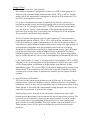
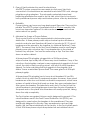
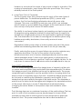
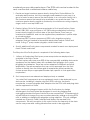
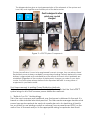
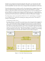
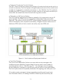
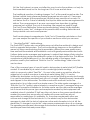
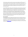
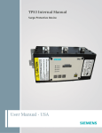
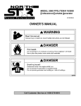
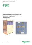
Solution Guide Turnkey Data Center Power Distribution Zonit Structured Solutions redefines the data center power distribution market with the Zonit Power Distribution System (zPDS™) which has unique patented functionality, high power density, complete power redundancy and unmatched reliability backed by a 25 year warranty. Figure 1 – Zonit Power Distribution Unit (ZPDU) Front View Change is a constant in data centers. It is part of the lifecycle. You have to deal with it. The Zonit Power System is designed to allow needed power configuration changes to be done at the rack easily and quickly. Zonit’s technology and methodology was designed to allow data center managers to take control of the data center lifecycle and effectively manage change. The Zonit Power System acts as a layer that is easily reconfigured to allow changes in power type or plug type to be done at the rack, without electricians. All that is needed is to move around the Zonit Power Distribution Unit(s) “ZPDU”, plugstrips (Zonit or 3rd party) and Zonit plug adapters as needed. Any changes in power distribution requirements are accomplished by simply plugging and unplugging system components at the rack using foolproof twistlock connectors. No changes are made to the other parts of the power distribution topology such as panel-boards and power whips or overhead busbar system power taps. The zPDS™ system reduces the total cost of ownership (TCO) for all of the common power distribution methods such as standard power whips from panel-boards (regardless of conduit type used) or overhead busbar systems using proprietary power taps. It also adds key benefits such as patented power phase load balancing for three-phase power and reduces the number of power receptacles that are affected by branch circuit power overloads or shorts by up to 66% and moves the point of branch circuit control to the rack Zonit Structured Solutions 1790 30th Street, Suite 140, Boulder, CO 80301 Phone: 720-266-0050 www.zonit.com [email protected] where it is easily accessible. The Zonit zPDS™ system can be easily deployed in both new build and retrofit scenarios to deliver these benefits. Figure 2 shows a typical data center power infrastructure. The left side of the diagram shows the core power infrastructure, utility feeds, transfer switches, Figure 2 – Typical Data Center Power Infrastructure generator, UPS units and panelboard(s) (or PDU). We call this the “core” part of the power infrastructure. There are only a few methods used to deliver power from the core data center power infrastructure to the rack. The zPDS™ system improves the functionality of and reduces the cost of all of these power distribution schemes. Here is how we do it. Zonit zPDS™ Goals & Methodology The zPDS™ system is the easiest power distribution system to use and live with, by design. It was designed to meet the following goals and meets them using the Zonit methodology. 2 Design Goals 1. Efficiently Power the Vast Majority The reality of modern IT equipment is that over 95% of all equipment in data centers requires single phase power either 120V or 200V+. Further, almost all of this equipment is designed to plug into 20A maximum (10A for 200V+) max branch circuits. If you try to anticipate a range of needs at the rack by choosing a particular model of rack mounted plugstrip with a mix of power types, such as C14 120V single phase and C19 208V split-phase receptacles, you will end up “losing” a percentage of the plugstrips receptacles, because you mostly won’t use them over the lifecycle of the plugstrip. This is wasteful, inefficient and inflexible. The Zonit system recognizes that the vast majority of IT devices need single phase power either in 120 or 200+ volts and the exceptions to this rule have harder to predict requirements. So, the Zonit system makes it very easy to supply reliable single phase power using very high quality 25 year warranty plugstrips and using reliable twist-lock low-cost plug adapters to supply the exceptions to single phase power. Also, all major plugstrip manufacturers make intelligent plug compatible 20A threephase plugstrips that work with the Zonit system. The choice of plugstrip type is usually driven by cost or what management software will be used. In the Zonit system, it is easy to change either the plugstrips (120V or 208V offered) or to use an inexpensive plug adapter to supply any type of 20A or 30A three-phase, split-phase or single phase requirement in any desired plug type. This covers 98%+ of all power deployment needs in the data center. The exceptions can cost-effectively be covered by either custom spec power whips or application specific power taps in busbar systems. 2. High Efficiency & Flexibility The Zonit system takes three-phase power all the way to the rack. Threephase power is the most efficient way to distribute power, it is naturally balanced, which is why utility companies use it in their power grids. Using three-phase to the rack with appropriate wiring gauges can save up to one-half of a percent of your power usage. Another key point is that all other commonly used power types (splitphase and single phase) can be derived from a three-phase source. This Is exactly what is done in a three phase panel-board or busbar system. This is a key part of why bringing three-phase to the rack makes such good sense and adds flexibility. The Zonit system uses the flexibility of a three-phase source in the most cost-effective and innovative ways possible. 3 3. Ease of Use& minimize the need for electricians All zPDS™ system connections are made via fool-proof twist-lock connections. No electricians are needed to relocate ZPDU units, change plugstrips or plug adapters. The automatic patented phase load balancing eliminates the need to do this task, which has to be done in both panelboard+power whip and busbar systems, often by electricians. 4. Reliability Power systems can have very long deployment lifecycles. They must be reliable. The zPDS™ system is guaranteed with a 25 year warranty! We know how important uptime is to data center managers and we are serious about our quality. 5. Minimize the Scope of Power Failures This is a point that is not often appreciated in data center power distribution. A three phase power whip or busbar tap box all share a neutral conductor and therefore all three hot conductor (X,Y,Z) circuit breakers must be pinned to trip together, by National Electrical Code (NEC). The same is true for the two circuit breakers used in a split-single phase power whip or busbar tap. If one breaker trips in the panel or busbar, they all open. You lose the entire whip or tap. That can take down an entire cabinet. A three phase 20A plugstrip, plugged into a 20A three phase whip or busbar tap usually will not have any circuit breakers. If any of the circuits on that plugstrip overload or any equipment plugged into it shortcircuit, the whip or tap box will go down, with all of its circuit breakers tripped. You lose everything that is plugged into the plugstrip, that doesn’t have a redundant power feed. The same goes for a 20A splitphase plugstrip. A three phase 30A plugstrip has to have circuit breakers if it has 20A outlets, which is what most IT equipment requires. However, those circuit breakers are often low cost thermo-activated components, which have a piece of metal in them that heats up when they are overloaded and then opens the breaker. This takes time and is slow. The fact is that the circuit breakers in most plugstrips are slower than the circuit breakers in the panel and so the panel circuit breakers will usually open first, taking down the whip completely. The Zonit system recognizes this issue and is designed to prevent it. The circuit breakers used in the Zonit Power Distribution Unit (ZPDU), are designed to open before the breakers in the panelboard. They are specifically designed for this role. They are expensive and very high quality. We test them individually at the factory. In the Zonit system each of four 20A three phase output receptacles has an individual circuit 4 breaker, so we reduce the scope of any power outage to one sixth of the number of receptacles, versus losing the entire power whip. This is a key reliability feature of the Zonit system. 6. Lower Total Cost of Ownership The Zonit system does this in several ways for each of the main types of power distribution. For traditional panelboard (PDU) + power whip systems, the Zonit methodology eliminates almost all power whip changes. This saves over $200 per rack per year which is an average amount spent on power distribution changes at the rack based on data from a study of forty-nine Fortune 500 data centers. The ability to use fewer busbar taps by not requiring one tap box per rack & inexpensive plug adapters instead of busbar tap boxes to supply the exceptions to single phase power in the rack leads to significant savings. Also, the elimination of the need to reconfigure the busbar system using ladders and possibly electricians, is less costly and much more convenient. Regardless if either power whips or busbar systems are used, the power phase load balancing eliminates the need to do this job manually. Finally, reducing the scope of power failures can avoid or minimize very expensive downtime. The fact of the matter is that modern IT infrastructures have a lot of service interdependencies and the data center manager doesn’t often know what system or critical service is dependant on what devices, and the IT staff can’t reliably tell him. So, he may have to assume that it is all mission-critical and all needs to stay up. Zonit zPDS™ Methodology The Zonit methodology separates the design issues of capacity at the rack vs. power and receptacle type and isolates their dependencies. This allows the design process to be simplified yet insure the desired results. The power receptacle grid configuration can be specified without worrying about the exact power or receptacle type in the rack. Instead the design process can be focused on matching the distribution capacity and location to the desired rack power capacity throughout the data center. This eliminates a painful issue for data center managers and designers, the repeated revisions of the power whip layout, as new IT department requirements keep changing the exact details of what power whips are needed in which location. The following steps are a condensed overview of the methodology. The key point to note is that a maximum power density target is chosen (watts needed per rack) and a uniform grid of power receptacles is deployed based on that. The power receptacles can be located underfloor or 5 overhead, per your data center layout. The ZPDU units can be located in the rack, over the rack or attached under a cable tray. 1. Decide on target maximum power density during Data Center lifetime. For enterprise data centers, this is the average power needed in each rack in a group of racks for each area of the data center. In a co-location facility this is the maximum power that needs to be available in any particular rack. The maximum power density possible is dictated by the maximum cooling capacity target, watts in must equal BTU out! 2. Deploy Uniform Grid of A-B power receptacles to Zonit specifications (threephase, 208V 30A, wye-configure w/ L21-30R locking receptacles) matching power density target(s) for each area of the data center. These can go overhead or underfloor, and can be supplied from panelboard + power whips or a busbar system. 3. Determine zPDS™ system components (ZPDU units, plugstrips and plug adapters) that are needed for immediate deployment needs. Obtain and install. If using 3rd partyr vendor plugstrips, obtain and install. 4. Specify additional Zonit system components needed for each new deployment need. Obtain and install. The lifecycle of the Zonit system is comprised of the following basic steps; 1. Uniform, A-B redundant Zonit-spec power receptacles are deployed and available in the Data Center The Zonit system will power over 98% of the commercially available data center equipment on the market today with available Zonit plugstrips (or 3rd party plugstrips) and adaptors. There are custom adaptors for MilSpec and other applications. The rare exceptions that can not be powered from the Zonit system or directly from the uniform grid of receptacles will be handled by custom power whips or appropriate busbar taps, specific to that application requirement. 2. Zonit components are ordered and deployed only as needed You order Zonit components as new equipment needs to be deployed in your data center. Installing it is simple, plug Zonit ZPDU units into the power receptacles, connect plugstrips and adaptors into the ZPDU units and plug data center equipment into them. 3. Adds, moves and changes happen within the Zonit system, by design All changes in the Zonit system are designed to occur by plugging and unplugging standard fool-proof twist-lock power connections. If requirements in a particular rack change, they are accommodated by adding or moving ZPDU units or adding or changing the plugstrips or plug adaptors. The only changes needed are to specify, order if needed and deploy the required Zonit components. The only exception to this cycle is when the capacity of the data center core power and cooling infrastructure needs to be upgraded. 6 The diagram below gives a visual representation of the elements of the system and how they work together over the lifecycle of the data center. PDU A PDU B Zonit is designed to allow quick, easy, no-risk changes! FIgure 3 – zPDS™ System Components The key benefits don’t have to be engineered for each change, they are always there! Redundant power is always available, power phase loading is always balanced, power delivery is segmented and controllable and the effects of branch circuit problems are minimized. Regardless of the number of deployment changes you make in your data center, the Zonit system always delivers these important benefits to every piece of equipment in your data center. Zonit Improvements to existing Power Distribution Methods We have now set the stage to describe in detail the benefits that the Zonit zPDS™ system brings to all of the common power distribution methods. 1. “Build-As-You-Go” Methodology This is the most common and traditional way that power is delivered to the rack. It is based on older industrial electrical practice. The data center manager decides what power type and receptacle he wants at a particular rack. An electrician is hired to run a conduit (or use existing conduit or raceway) from a panel-board (PDU) on the wall or floor to the rack and put in the appropriate wiring, receptacles and circuit 7 breakers. The changes at the panel-board are often done “hot” because the data center manager cannot shut down the PDU for changes, which has risks. This cycle must be repeated over and over for each change in power requirements at the rack. This methodology does not scale up well to the change rates of modern data centers which can have thousands of branch circuits. We have developed TCO models based on data from studies by the Uptime Institute that show that the ongoing cost of power distribution changes can average over $200/rack per year, a huge expense. The end of the power whip is the wrong place to make changes in a data center with many branch circuits and many, many IT devices which are frequently changing. The Zonit system can be used with the “Build-As-You-Go” methodology. It changes it to the “Build-It-Once” method! If retrofitting an existing data center, it will deliver a number of advantages. a. Reduced Conduit Count By National Electric Code (NEC) a conduit can not be changed while energized or “hot”. This is a key reason why it is normal practice to run one or more conduits to every rack, if you have to make a change to a power whip, you want to turn off the power to as few racks as possible. This is why in many older data centers there are often many abandoned power whips, it was not possible to get the downtime window to shutdown the power whip and reconfigure it. It was easier to run a new whip and abandon the old one. The Zonit system offers the ability to reuse existing conduits or raceways in an innovative fashion as shown below in Figure 4. Figure 4 – Zonit Multi-Whip Methodology 8 The Multi-Whip methodology simply combines the wiring for a group of power whips into one conduit path (which can consist of one or more conduits that were run in parallel if needed). This strategy is practical because of the nature of the Zonit system. The power whips once run, are left alone and never changed. The point where changes are made is in the Zonit system components, not the power whips. So, it is practical to run a set of power whips as a group through one (or more) conduits. You are not going to need to change them later, so you don’t need the ability to turn them all off at once. Multi-Whip can be used in a new build-out or in a retrofit, as needed. It reduces the number of conduits needed, which can often help reduce conduit clutter and improve underfloor airflow. b. Reduced Circuit Breaker Count The most common power whip deployed for many years was a single-phase 20A whip terminated in a quad-receptacle metal box. This made sense since this was the most common need, as we discussed earlier. However, large numbers of single phase 20A whips are not the most effective way to use the available circuit breaker stations in a panel-board. The Zonit zPDS™ methodology significantly reduces the number of circuit breakers used in the panelboard vs. standard single phase 20A power whips as shown below in Figure 5. Also note the reduction in the number of power whips by a factor of four. Using Multi-Whip, the conduit count could easily be reduced by another factor of four to only four power whips. Figure 5 – Zonit vs. Traditional 9 c. Reduced Conductor Count & Volume The NEC controls both the number and volume of conductors that can be put in a conduit or raceway. The Zonit system will significantly reduce both the volume and number of conductors in conduits or raceways vs. the “Build-As-You-Go” method. Installing the zPDS™ system in situations where conduits or raceways are filled up is often both the easiest short-term fix and best long-term solution. d. Elimination of All Points of Failure The Zonit system is designed for maximum reliability. All components carry a 25 year warranty. The ZPDU unit has completely independent A-B power paths internally. The nature of the Zonit zPDS™ system makes it possible to go one step further and deploy with complete redundancy. Diagram 6 below shows how to interleave ZPDU units so that no rack is served by only one ZPDU unit. Figure 6 – Zonit Interleave Deployment Method e. Zonit Cost Savings The Zonit Power Distribution System can save data center managers with traditional power distribution a great deal of money and is much easier to operate and live with vs. “Build-As-You-Go”. The average cost of ongoing power distribution changes is over $200 per rack per year, as discussed earlier. The Zonit system almost completely eliminates this ongoing year after year cost. If the data center manager is facing upgrading panel-boards to get more circuit-breaker stations, or adding conduits or raceways because they are 10 full, the Zonit system is a more cost-effective way to solve the problem, not only for the immediate need, but for the long-haul. Do it once and be done. The traditional practice of making changes “hot” at the panel-board has risks. The Uptime Institute study referenced earlier measured an error rate of 1.3 errors per thousand changes at the panel-board. While this may seem like a low rate, it is well below the 4 or 5 nines of reliability that top-tier data centers are engineered to deliver. The consequences of an error can range from downtime to getting someone hurt or killed. The cost of downtime can range from small to huge. The Zonit Power Distribution System and methodology, almost totally eliminate the need to make “hot” changes at the panel-board, avoiding these risks and their potential costs and consequences. Zonit has developed comprehensive Total Cost of Ownership calculators so that you can analyze the specifics of your situation and know what you can save. 2. “Modular Pre-Built” Methodology The Zonit zPDS™ system also can enable more cost-effective methods to design and build or upgrade data centers. The Zonit methodology improves on the traditional means by using a methodology that is repeatable, delivers the same quality every time and reduces material and installation costs with greatly reduced risks and costs. It allows data center managers and engineers to extend their design efforts using the Zonit methodology and power distribution system to the data center floor. This delivers a professional, predictable result, vs. the variable quality of the legacy trade practices used by the traditional “Build-As-You-Go” methodology. Here is how this can be done. One of the common types of conduit used in data centers is metal-clad (MC) flexible conduit. It is available in just metal or with a water-tight plastic-coating, which is commonly called “Seal-Tite”. It is most often used as an add-on after the original set of conduits was done in electrical metal tubing (EMT). It can be Installed by electricians on site by placing the conduit and pulling conductors through it, or can be modularly manufactured: pre-cut to length, labeled properly, terminated and shipped to the data center. The latter construction method is much less expensive but is not often used for a simple reason. The data center manager of a “Build-As-You-Go” facility is almost always in a reactive mode. IT managers bring new equipment forward for installation in the data center and the data center manager has to insure that the power type and receptacle needed by that equipment are available when it is installed. IT staff are often not clear on the power specifications needed, because they are usually not familiar with power and they are not responsible for making sure it is available. So, the power requirements often are unclear and change at the last minute. So, the easiest way for the data center manager to deal with the lack of advance notice and information is to just tell the electrician “It changed, now do this” when power requirements show up or change. The operating environment discourages the extra time and planning needed to order modular pre-manufactured power whips. 11 The Zonit zPDS™ system dramatically changes this dynamic. All of the power whips in a Zonit system deployment will be deployed once and not change. This allows the use of modular prefabricated redundant A-B power whips. The length of each cable can be determined from examination of a plan view of the data center with the rack layout indicated. We have developed proprietary Zonit AutoCAD® design templates to facilitate this process. The designer lays out the power whip paths and specifies their capacity and type and the template calculates a bill of materials for that layout. The completed template is sent as part of the order process to Zonit Structured Solutions and the bill of materials is confirmed. The power whip lengths are computed from the site plan drawing(s). The metalclad cables can then be modularly manufactured: pre-cut to length, labeled properly, terminated and shipped to the data Figure 7 – Modular Pre-Fabricated Whip center. An example prefabricated Seal-tite power whip is shown in Figure 7. This has several major benefits: Labor costs are greatly reduced because it is very time intensive for electricians to bend and install hard conduit and/or pull conductors through flexible conduits. The Zonit zPDS™ “Modular Pre-Built” reduces these labor costs by up to 40%. Also, prefabrication at a site designed for this purpose and operated in an assembly line type environment is intrinsically more efficient. The quality control is much easier to maintain at a higher level, and pre-testing prior to leaving the factory ensures electrical code compliance. Also, it is easier to insure quality at the site if the whips are installed at once or area by area vs. the ongoing challenge of making sure that each add or change is done right in the “Build-As-You-Go” method, which forces the data center manager into the ongoing role of a general contractor. The use of pre-cut MC cable insures that the ends can be properly prepared for installation and carefully labeled and coded to an installation design drawing. The metal-cladding is flexible thus easing installation routing and insuring that no EMI issues occur. It also can be specified with an internal and/or external moisture seal, for environments that need or want this feature and is more water resistant than hard conduit, since it only has one installation “joint”, where it enters the outlet receptacle box. It also offers 12 much greater power capacity vs. conduits or raceways in the same underfloor or overhead cross-section, under NEC code. For example, a space of 12”x24” matching a 2'x2' floor grid can hold 171 MC cables each of 5 conductor 60A capacity. Pre-labeling and keying to the installation drawing helps insure correct installation both at the PDU and receptacle and again lowers electrician labor time. Diagram 8 below shows an example deployment of the Zonit “Modular PreFabricated” system. The example shown is underfloor power distribution, but it could also be done as an overhead deployment. 42 Station 3 Phase panel 14 Zonit feeds per panel Panel Feeder Zonit ZPDU Pair of NEMA L21-30R receptacles in boxes Wireway Pair of Russel-Stol 60A receptacles in boxes 60A MC whip cut to length and terminated with a pigtail at the PDU end, and a box with receptacle at the rack end 30A MC whip cut to length and Uni-Strut supports use standard terminated with a pigtail at the PDU end conduit clamps to secure MC and a box with receptacle at the rack end whips under the floor Figure 8 – Zonit Modular Pre-Built Example Deployment The key point is that the nature of the Zonit system, use of a uniform grid of power receptacles that are not changed once deployed, make the “Modular PreFrabricated” methodology practical to use. 13 3. Zonit + Busway Power Distribution Busway systems were invented as an industrial power system for use in factories. That is their most common usage. They distribute from overhead, avoiding putting conduits across factory floors and work in the same fashion as track lighting. They have recently become popular for data center power distribution, because they avoid some of the issues of the “Build-As-You-Go” methodology. The Zonit zPDS™ system improves the busbar power distribution method by solving several issues that it cannot. The first is power phase balancing, a busbar system is a three-phase power distribution system. The tap boxes inserted into the busway supply the receptacle types in the amperage desired. The tap boxes for split-phase and single phase power receptacles must be chosen to tap a particular phase or set of phases. Each new tap box that is deployed must be manually specified and configured to balance the three-phase power usage. This often involves using an electrician. The Zonit system eliminates this task and automatically balances the power phase loading, a significant operational simplification and cost saving. Figure 9 – Busbar Tap Box Install A busbar power tap is exactly like a power whip from a panel-board in regards to National Electrical Code. If a tap box feeds a split-single or three-phase power receptacle, the circuit breakers in that tap box must be pinned together if they share a common neutral. As discussed in detail earlier, this means that if any of the circuit breakers in that tap box are tripped by an overload, anything powered by that tap box will lose power. The Zonit system reduces the number of receptacles that are affected by an overload or short, again as described earlier. This is a significant improvement that the Zonit system provides. Zonit makes upgrades of busbar systems much easier to accomplish. Power densities in data centers have been on an increasing curve, driven by ongoing increases in CPU core count and power usage. The busbar capacities deployed over the last few years are in the range of 225 to 400 amps (three-phase 208V). A new range of upgraded busbar systems with capacities in the 600-800 amp (three-phase 208V) range are now coming to market. When a busbar system is upgraded, it must be powered down. This means that every tap box that is installed in that busbar system will be powered down during the upgrade process. This means a lot of racks will go dark, a major downtime event. The Zonit system is a uniform A-B redundant system. It is much easier to power down a Zonit powered rack, since an alternate power source is always available in the rack. 14 This may or may not be the case in a busbar system where tap boxes are non-uniform and are located on an as needed basis. The upgrade path for a busbar + Zonit zPDS™ system is much easier. The new busbar is installed while the old busbar is active. New Zonit specification power taps are installed in the new busbar. Each Zonit ZPDU unit can individually be shutdown on one side (A or B) and the NEMA L21 locking power input plug disconnected from the old busbar and moved to the new. These steps can be repeated for the other input of the ZPDU unit and so on for each ZPDU unit. The Zonit system guarantees a simple and straightforward upgrade path. The last issue to discuss is cost savings. Busbar systems are significantly more expensive to install than panel-boards+power whips. Their power taps are proprietary to each system and vary in cost depending on receptacle type and any additional features. The Zonit zPDS™ system can significantly reduce the types and number of tap boxes required in a busbar deployment and in doing so, lower the cost of the system. The normal way to deploy tap boxes is to use one or more for each rack and have each one feed a plugstrip in the rack. The reason for this one-to-one ratio is the exact same one as discussed for power whips; the need of the data center manager to minimize the number of receptacles affected by a problem with any single branch circuit. Figure 10 – Zonit ZPDU Unit Circuit Sub-Division &Protection 15 The Zonit system makes the ratio of tap boxes to racks flexible. The ZPDU unit protects each power lead of each three-phase output receptacle (effectively a branch circuit) individually, as shown above in Figure 10, so that only the number of tap boxes that are needed for the average power per rack need to be deployed. There is no need to deploy a tap box per rack to reduce the domain of failures. The Zonit system can reduce the number of tap boxes needed by up to a factor of four or more, which saves money. The Zonit zPDS™ system lowers cost in busbar systems in other ways also. As discussed earlier, the Zonit system is optimized to cost-effectively provide the dominant power requirement, single phase power, and uses inexpensive plug adapters for the 5% or less of power requirements that are not single phase. It is much easier and more cost effective to use Zonit plug adapters for all spilt-phase and three-phase power requirements in 20A and 30A and each of these plug adapters will be individually protected. It is more expensive to deploy additional tap boxes for each of these power requirement exceptions. The Zonit system allows the data center manager to use very few additional tap boxes, almost all of the tap boxes deployed will power ZPDU units. The only exceptions to this rule are the very few times that a rare power deployment need is encountered, for example an 80 amp single phase branch circuit. These exceptions are quite rare. More Information The Zonit zPDS™ system was designed with extensive input from people who have a lot of experience in building and operating data centers through their entire lifecycle. It was created to make data centers much easier and more cost-effective to build and operate. It works with and enhances all of the common data center power distribution methods. It can easily be installed in new construction or retrofits. Please contact us at [email protected] for more information and to discuss how it can be used to meet your needs. 16