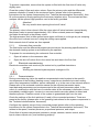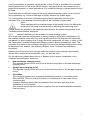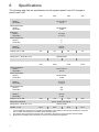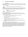
1
MANUAL Installation, operating and maintenance instructions for compact district and local heating stations pewoV-max The illustration is presented as an example. This system depicts equipment that is available at extra cost. © PEWO Energietechnik GmbH www.pewo.de Subject to errors and technical modifications. pewoV-max – Version 1.0 – (09/14) 2 Contents 1 YOUR SYSTEM FEATURES.............................................................................. 5 2 BEFORE YOU BEGIN ........................................................................................ 5 2.1 Symbols used ..................................................................................................... 5 2.2 Qualification and training of personnel ................................................................ 6 2.3 2.3.1 Safety instructions............................................................................................... 6 Standards and directives .................................................................................... 7 3 YOUR SYSTEM .................................................................................................. 9 3.1 3.1.1 3.1.2 3.1.3 3.1.4 How it works........................................................................................................ 9 Controlling mixed heating circuits ....................................................................... 9 Protection from overtemperature ...................................................................... 10 DHW generation with plate heat exchanger ...................................................... 10 Heat meter ........................................................................................................ 10 3.2 Set-up ............................................................................................................... 11 3.3 Your system components.................................................................................. 12 4 INSTALLATION ................................................................................................ 15 4.1 4.1.1 4.1.2 4.1.3 Hydraulic connection ......................................................................................... 15 General information .......................................................................................... 15 Hydraulic circuit diagram ................................................................................... 15 Installation work and commissioning preparations ............................................ 15 4.2 4.2.1 4.2.2 4.2.2.1 4.2.2.2 4.2.3 4.2.4 Electrical connection ......................................................................................... 16 Mains connection .............................................................................................. 17 Control cabinet .................................................................................................. 17 Control cabinet with terminal board................................................................... 17 Control cabinet with terminal block ................................................................... 20 Circuit diagrams ................................................................................................ 20 Connection of network components .................................................................. 20 5 COMMISSIONING ............................................................................................ 22 5.1 5.1.1 5.1.2 5.1.3 Filling and venting ............................................................................................. 22 Secondary ......................................................................................................... 22 Primary.............................................................................................................. 22 Volumetric flow controller .................................................................................. 23 5.2 5.2.1 5.2.2 Electrical commissioning ................................................................................... 23 Parameterisation ............................................................................................... 23 Functional testing for factory-wired systems ..................................................... 24 5.3 5.3.1 5.3.1.1 5.3.2 5.3.3 Hydraulic commissioning .................................................................................. 24 Primary balancing ............................................................................................. 24 Hydraulic balancing with control valve and differential pressure controller for flow limitation/control ................................................................................................ 24 Hydraulic balancing for a combined control valve with flow controller for flow limitation/control ................................................................................................ 24 Secondary balancing ........................................................................................ 24 Hydraulic balancing of the domestic hot water heating system ......................... 25 6 SPECIFICATIONS ............................................................................................ 26 5.3.1.2 3 7 SERVICE INFORMATION ................................................................................ 27 7.1 7.1.1 7.1.2 Maintenance ..................................................................................................... 27 Maintenance work ............................................................................................. 27 Malfunction-related or maintenance operations ................................................ 27 7.2 Troubleshooting ................................................................................................ 28 7.3 Dismantling ....................................................................................................... 29 7.4 Manufacturer information & customer service ................................................... 30 4 1 Your system features pewoV-max is a modular heat transfer station between the district or local heating network and the domestic heating system. This is separated from the heating network by a plate heat exchanger. A heating circuit manifold is integrated as standard. The primary and secondary media connections are located at the top or at the bottom. Suitable modules, such as heating circuits or domestic hot water heating, can easily be connected to the pewoV-max. You can obtain these modules directly from us at PEWO Energietechnik. pewoV-max is manufactured using PEWO Sandwich Technology (PST). Pipelines and components are housed three-dimensionally in a non-corrosive, sandwich-style cabinet made of closed-cell polyurethane foam. Superior heat insulation is therefore achieved, in accordance with the Energy Saving Ordinance (EnEV). If, at customer request, parts of the insulation are dispensed with, the system's thermal insulation capacity changes. pewoV-max is supplied as a wall-mounted version, and where appropriate with freestanding installation frames. In both installation versions, all the system components and operating elements remain accessible from the front, maintaining ease of servicing postinstallation. If you have any questions, please do not hesitate to contact us. Your PEWO Team 2 Before you begin This manual contains basic information on setting up, operating and maintaining the system. As the operator's authorised specialist personnel, please read it carefully. Keep the manual with the system at all times so that information can be found quickly. Please consult the information given in the Safety instructions section, as well as the notes highlighted in the individual sections. 2.1 Symbols used Danger signs and warnings are specifically indicated in the manual. They must be read very carefully and taken into account! Danger! This is a danger sign. It indicates imminent danger. If disregarded, this can lead to serious injury, or even a life-threatening situation resulting in death. Attention! This is a warning. It indicates potential danger. If disregarded, this can lead to serious injury, or even a life-threatening situation resulting in death. Note This is a general note. It contains additional information on the section of text. Danger signs and warnings directly attached to the system must also be read carefully and taken into account! Care must be taken to ensure that these remain fully legible. 5 2.2 Qualification and training of personnel All specialist personnel authorised by the operator who are involved in operation, maintenance, inspection and installation must be suitably qualified to carry out this work. Personnel responsibilities, competence and supervision must be clearly defined by the operator. Personnel who do not have the necessary expertise must be trained and instructed. If required, the operator of the system may commission PEWO Energietechnik GmbH to take care of such training. Furthermore, the operator must ensure that authorised specialist personnel have been trained to operate the system. Note It is recommended that a handover certificate is issued to the operator once the system is installed. An authorised company should be assigned with commissioning the system. This is something that we at PEWO Energietechnik GmbH also undertake. Please use the ‘Order for Commissioning’ in the ‘Technical documentation’ document. Note For long-term, best possible system operation we recommend entering into a maintenance contract. Any system irregularities can then be identified and remedied at an early stage. 2.3 Safety instructions Failure to comply with the safety instructions and improper handling of the system, which can lead to the malfunction of key system functions, poses a risk to personnel. This may also invalidate any warranty claims. In particular, if disregarded the following risks may lead to serious injury, or even a life-threatening situation resulting in death: Danger! Risk of electric shock. Danger due to water and/or steam spurting out under high pressure. Risk of burns due to hot water or steam or hot pipes and components. Danger due to mechanical impact (crushing). Any procedures carried out on the system (such as installation, commissioning, adjustment, maintenance and dismantling) may only be carried out by qualified specialist personnel. Attention! The system must only be installed in a frost-proof, dry and well-ventilated room. This room must conform to the requirements of the district heating supplier and should be equipped in accordance with the design guidelines of the AGFW (German District Heating Working Group). The actuators on the valves must not be dismantled during operation. This could result in them being destroyed. Dismantling should only be carried out when the shut-off valves are closed and when the system has cooled down. The system must not be put into operation while it is dismantled. The PEWO system should not run via site power supply! Failure to observe will void the warranty. 6 Note In terms of its electromagnetic properties, the system is suitable for both the residential and commercial sectors. Safe working practice It is essential to comply with the safety instructions listed in this manual, the existing national regulations on accident prevention and the operator's own internal work, operating and safety regulations. If there is any risk due to hot system components, the customer must protect these components from being touched. Make sure that there are no electrical power hazards. VDE and local energy supply company regulations must be observed. The operator is responsible for ensuring that all maintenance, inspection and installation work is carried out by authorised and qualified specialist personnel, who are completely familiar with the Technical documentation. Unauthorised conversion and spare parts use Any conversions or modifications to the system may only be carried out further to consultation with the manufacturer. Original spare parts and accessories authorised by the manufacturer, PEWO Energietechnik GmbH, serve to ensure safety. The use of other parts may nullify the liability of the manufacturer of the system, PEWO Energietechnik GmbH, for any resultant consequences. Warranty Any warranty claim is subject to the system having been properly installed and commissioned in accordance with the relevant installation, commissioning and operating instructions. Necessary installation, commissioning and maintenance work may only be carried out by competent and authorised persons. Transport and storage Transportation dimensions, weights and installation openings or open space required to transport the system must be taken from the dimensional drawings. The system is designed to be transported upright using a pallet truck. Care must be taken that the system components and parts in the system are not damaged and that cables and wires are not yanked, pinched or buckled during transport. The system should be stored upright (or lying on the frames) in a dry, frost-free location. We recommend covering the station with tarpaulin to protect it from dust and dirt. During longer periods of storage, the actuators and pumps must be moved manually in order to prevent the components becoming blocked. Danger! The operational reliability of the supplied system is only guaranteed if it is used for the intended purpose. The limits specified on the system's nameplate must be complied with Attention! The system must be transported using approved lifting equipment! The system must be protected from moisture. The system must always be stored in frost-free conditions, as residual water remains in the pipelines and system components after the system has been pressurised and flushed. 2.3.1 Standards and directives PEWO systems are manufactured in accordance with the standards and directives in force. Refer to the EC Declaration of Conformity in the “Technical documentation” document for information on this. 7 Furthermore, the VDE regulations and technical connection conditions (TAB) of the local power supply company (EVU) also apply. PEWO systems achieve superior heat insulation with the patented PST heat insulation (PEWO Sandwich Technology). They therefore conform to the principles of the Energy Saving Ordinance (EnEV) regarding improving the energy balance of buildings and systems for heating, cooling, air-conditioning and lighting technology and also hot water supply. Local conditions at the system installation site may affect this. In this event, appropriate measures must be taken to restore the required heat insulation. If, at customer request, parts of the insulation are dispensed with, the system's thermal insulation capacity changes. 8 3 Your system The pewoV-max is the connecting link between the district heating network and the domestic system. Both networks are hydraulically separated by the plate heat exchanger used. The plate heat exchanger used is made of stainless steel and covers a wide performance spectrum due to its long thermal length. For optimum system control, the secondary flow temperature sensor is installed against the volumetric flow, directly on the plate heat exchanger. A heating circuit manifold is integrated as standard. The components of the pewoV-max system are enclosed by a sandwich construction made of PUR foam. Self-supporting metal inlays in the form of stabilisers are incorporated in the back panel. Fastening elements for mounting the system on the wall and drill holes for bolting the control cabinet are located here. With the PUR foam insulation cover on, 110% heat insulation is achieved in accordance with the Energy Saving Ordinance (EnEV). The control cabinet under construction can also be made lockable in combination with the insulation cover, depending on the design. The primary and secondary media connections are located at the top or at the bottom. This design feature, as well as its compact construction, means that the pewoV-max can also be installed in very tight spaces. The connections available on site are connected to the system using a flat sealing screw joint and welding socket piece, including a special hightemperature O-ring. With the integrated strainers, a fine mesh can be retrofitted on the primary and secondary side. The safety valve is integrated into the structure with an exhaust pipe. The control cabinet is made of sheet metal and designed with IP54 protection. Installing certain controller models in the door panel results in IP40 protection. The control cabinet has spare space for additional equipment, for example a WLAN modem. The controller and the thermometers for the primary and secondary side are embedded in the control cabinet door panel recesses and are therefore easy to read or operate from the outside. The integrated controller model is preselected for the operations on site. All systems are equipped with a weather-compensated heating control system as standard. The heat meter can be freely accessed and read from the outside. 3.1 How it works The hydraulic set-up of the pewoV-max depends on the technical connection conditions of the district heating supplier and the technical requirements due to the district heating network parameters and the domestic system. Selected functions of the pewoV-max are described below. 3.1.1 Controlling mixed heating circuits The flow temperature is controlled via the return admixture principle. The control valve (72) * on the three-way valve (15)* is activated in a targeted way so that the required quantity of return water is added to the flow water. This lowers the flow temperature in a controlled manner. The external temperature sensor (6)* provides the current outside temperature reading to the electronic controller (7)*. The controller determines the flow setpoint from the actual value of the outside temperature (in the case of weather-compensated systems even more readings, e.g. wind and intensity of sun radiation) and the heating characteristics. You can find explanations about the heating characteristics in the controller user manual in the ‘Technical documentation’ document. * The figures correspond to the system components of the P&ID included in the ‘Technical documentation’ document. 9 The flow temperature sensor (75)* records the actual value of the flow temperature. From this and the flow setpoint, the controller determines the required control path for the actuator (72)* of the three-way valve. This accomplishes a greater or lesser degree of admixture of the required flow temperature. The return temperature sensor (75)* is only provided on request. This can be used to implement return temperature limitation. In the event that a determined maximum return temperature is exceeded, the control valve is force-operated. The flow temperature is reduced by force. Once a day the controller carries out a forced pump, mixer and valve operation. This is particularly necessary during the summer months, in order to be able to guarantee the mobility of the control elements at the start of the heating season. Therefore the system also needs to be electrically connected and activated during the summer break. 3.1.2 Protection from overtemperature If the permissible domestic system temperature is the same as, or higher than, the maximum network flow temperature, then temperature protection of the domestic system is not needed. If the domestic system temperature is lower than the maximum network flow temperature, then the domestic system must be protected from overtemperature in accordance with DIN 4747-1 (type-tested temperature controllers or safety temperature limiters). These components must then trigger an actuator with a safety function (emergency function), which closes currentless against the system pressure when triggered, switching off the system. 3.1.3 DHW generation with plate heat exchanger This DHW generation variant enables the provision of greater quantities of DHW, such as those required in apartment blocks. Its advantage lies in the relatively small dimensions of the system and relatively small storage tanks for providing large quantities of DHW. The DHW is heated in the flow by the plate heat exchanger, with hot water reserves available in the buffer tank even during peak periods. The dimensions of the plate heat exchanger are such that when providing the necessary hot water temperature (usually 60 °C), the exchanger's primary temperature does not need to go above 65 °C (maximum value 70 °C), which means that scaling in the exchanger is prevented or minimised even in the event of increased water hardness. pewoV-max systems feature thermal disinfection. At a specified point in time, the DHW (secondary) is heated to a temperature of over 60 °C for a specified period of time. This greatly reduces the risk of legionella. You can find more information in the controller user manual in the ‘Technical documentation’ document. 3.1.4 Heat meter The heat meter is set predominantly by the energy supplier. The installation point for this is implemented as a placeholder in the system at the factory. Devices for mounting the temperature sensor of the heat meter (threaded socket, immersion sleeve etc.) are also integrated in the transfer section. When installing, please observe the instructions and notes in the heat meter documentation. 10 3.2 Set-up The wide range of system variants that we offer means that we can fulfil customer requirements quickly and efficiently. The following illustration is therefore an example of our pewoV-max product line. Please refer to the hydraulic circuit diagram (P&ID) in the ‘Technical documentation’ document to see the components and functions of your pewoVmax system. In the illustration, the pewoV-max V75 is shown with 1 mixed heating circuit and 1 unmixed heating circuit. The system-relevant components are identified. Features, size, pipe layout etc. may vary widely from the system that you have purchased. Flow heating circuit 1 Return heating circuit 2 Ball valves with thermometer Circulating pump 3-way mixing valve with electric actuator Flow heating network (alternative) Return heating network (alternative) Mixed heating circuit Pressure gauge Controller (DDC controller) Thermometer primary/secondary for flow/return Plate heat exchanger Volumetric flow controller with electric actuator Diaphragm safety valve Heat meter adapter Connection for external expansion vessel Strainer Non-return valve Venting and draining valve Ball valves Circulating pump Ball valves with thermometer Return heating network Unmixed heating circuit Flow heating network Flow heating circuit 2 Return heating circuit 2 Fig. 1: pewoV-max V75 11 3.3 Your system components Depending on function, the components described below do not always form an integral part of your system. Shut-off valve In a pipe system, the shut-off valve shuts off the flowing medium in the entire installation or in parts of it. The shut-off ball valve is a variant that is frequently used. This blocks the flow of medium in pipelines or releases it again. To achieve this, a lever attached to the housing is operated manually by rotating it ninety degrees. Due to their mechanical design, ball valves are regarded as having excellent sealing properties. A ball cuts off the flow using pressure. Expansion vessel The expansion vessel regulates pressure conditions in a closed hydraulic system. The medium in the pipe system expands at high temperatures and contracts again at low temperatures. The expansion vessel compensates for this change in volume. External temperature sensor The external temperature sensor is a measuring unit for determining the outside temperature. The result is transmitted to a control unit or display unit. The control unit uses the measured value to control the thermal behaviour of the medium in the system. The sensor makes it possible for the system control to be guided by the outside temperature. DDC controller Direct Digital Controller, see Controller. Differential pressure controller The differential pressure controller is a system component which controls the flowing medium in a pipe system without any external power supply. It controls the constant value of the differential pressure between a pipe system's flow and return. The differential pressure is determined when planning the domestic heating system. The differential pressure controller is normally employed in a valve in combination with a volumetric flow controller/limiter. Straightway valve In a straightway valve, the flow rate of a medium within the pipe system is controlled via a valve cone. The flow coefficient is determined by the geometric shape of the cone. Continuous flow control is possible. Filling and draining valve The filling and draining valve is used to fill the system for commissioning. The individual pressure of the domestic heating system at the relevant pressure gauge must be noted during this process. This must not be exceeded. This valve can be used to empty the system for maintenance work. Ball valve See shut-off valve. Adapter The adapter is pre-installed at the factory as a placeholder in the system. It's easy to install an additional system component at a later stage. pewoTFS The PEWO Thermo Fluid System is a dynamic, robust, thermostatic temperature control system for DHW and space heating. 12 Plate heat exchanger The plate heat exchanger transfers thermal energy from a hot medium to a cold medium. The energy is transferred between two physically separate material flows by means of a thermally conductive material. They are separated by plates which are attached to each other. Chambers are formed due to the constructive form of the plates. Hot and cold media flow through these on an alternating basis. This causes the cold medium to warm up and the hot medium to cool down. Controller The controller (also DDC controller) uses a configurable programme to control the behaviour of the system. Inputs are logically linked to outputs. The system can be adapted to the local conditions by configuring the limits, setpoints, system type and other control characteristics. Check valve Switching operations by system components result in varying flow velocities of the medium within pipe systems. This can lead to unwanted reversal of the flow direction of the medium. This results in great mechanical stress on the system components and pipe system. The check valve prevents reversal of the medium flow direction. The mechanical stress on the system is minimised. Strainer Impurities can build up or get into pipe systems with flowing media. This results in obstacles moving throughout the system, clogging up system components. Hence the need for strainers to ensure adequate protection. With this type of fitting, a filter medium is arranged at an angle against the direction of flow. Wire cloth is used for this. Safety temperature monitor (STM) The safety temperature monitor is a temperature limitation device. It keeps the temperature in the domestic heating system below a maximum permissible value. Automatic reset occurs upon activation, after the sensor temperature has fallen below the set limit value by an amount equal to the differential gap. A safety temperature monitor (STM) is a temperature monitor (TM) with enhanced security. Diaphragm safety valve The diaphragm safety valve prevents the mechanical destruction of the domestic heating system in the event of increased thermal expansion of the flowing medium. As a rule the diaphragm safety valve is closed. If the system pressure increases inadmissibly, the valve responds. The set pressure is permanently set at the factory. Once the system returns to permissible pressure, the diaphragm safety valve automatically closes. Storage tank charging pump The storage tank charging pump is used to store the thermal energy of the flowing medium in a storage tank for DHW generation. If the setpoint at the storage tank sensor drops due to the consumer withdrawing DHW, the storage tank charging pump is activated. Actuator The actuator converts an electrical or hydraulic signal into a mechanical signal. The flow of medium in a pipe system is controlled via mechanical impact on an actuating element in rotary or linear motion. Temperature sensor The temperature sensor is a measuring unit for determining the temperature. The result is transmitted to a control unit or display unit. The control unit uses the measured value to control the thermal behaviour of the medium in the system. The external temperature sensor makes it possible for the system control to be guided by the outside temperature. 13 Volumetric flow controller/limiter The volumetric flow controller/limiter is a system component which controls or limits the flowing medium in a pipe system without any external power supply. The flow rate of a medium within a pipe system is controlled or limited. The flow rate is the volume of medium that flows through a local cross-section of the pipe system during a certain period of time. The flow rate corresponds to the volumetric flow rate. The volumetric flow controller/limiter is usually used in combination with the differential pressure controller. 14 4 Installation 4.1 Hydraulic connection 4.1.1 General information Note When connecting to the district or local heating network, the technical connection conditions (TAB) of the energy supply company (EVU) must be observed. PEWO systems come with a high degree of prefabrication at the construction site. This ensures that installation is quick and inexpensive. All pipeline connections must be de-energised Only use appropriate tooling, so as to prevent mechanical damage to the system and eliminate the risk of injury. Ensure that the system is installed in the correct position and that the connections are all leak-tight. Note Use sealing material specified by the operator or implement VDI Guideline 2035 Sheets 1 and 2 to determine the appropriate sealing material. Prior to commissioning, all primary connections to the local or district heating network, all secondary heating circuits, expansion vessels and, where necessary, hot water tank, coldwater connections and circulation pipes must be connected. Attention! All secondary circuits must be flushed before being connected to the system! When connecting a DHW heating system, please observe DIN 1988-200. 4.1.2 Hydraulic circuit diagram The system's operating principle is illustrated in graphical form in the hydraulic circuit diagram (P&ID). The individual system components are specified in the circuit diagram. This forms an integral part of the ‘Technical documentation’ document. Please refer to the ‘Drawings’ section. 4.1.3 Installation work and commissioning preparations Attention! Following welding work, please ensure that the system's shut-off valves are closed. This prevents any unwanted filling/emptying of the system during commissioning, any potential pressure hammers are intercepted, and slowly opening the valves during commissioning can ensure a faster response to any leaks. The system is delivered ready for connection, mounted on a base frame. It must only be installed in a frost-proof, dry and well-ventilated room. This room must conform to the requirements of the district heating supplier and should be equipped in accordance with the design guidelines of the AGFW (German District Heating Working Group). The system must be installed in such a way that there is sufficient space available for maintenance and operation. The maximum room temperature must not exceed 40°C. The installation room needs to have floor drainage. Prior to installation, check the system for any obvious damage. In addition, check that all detachable connections are secure and retighten them if necessary. The system is flushed at the factory prior to delivery. Prior to installing the system, check that all pipelines for connection, both from the district heating supplier and from the domestic system, are flushed and free of particles. 15 Welding work must be carried out by certified welding personnel and in accordance with applicable standards. Please pay particular attention to the following installation and processing instructions: For welding work to be carried out correctly, the earth cable (return line) must be connected close to the welding point. Do not use bolted connections on the system for this. Ensure that no welding residues get into the pipeline. Open the shut-off valve. Make sure that there is sufficient heat dissipation upstream of the sealing components of the shut-off valves. Pipeline connections to the system must be de-energised. Masonry that is capable of load-bearing is required for mounting the system to the wall. Dowels that are suitable for the wall should be used as fixing devices. If the wall is not capable of load-bearing, the system must be mounted to a standing frame. 4.2 Electrical connection Electrical connection work must only be carried out by qualified electricians. Danger! Working on electrical systems poses a danger to life. Prior to beginning installation, all components that need to be installed by the customer must be connected. In particular, this relates to the power supply via the terminal point in the customer's central electricity supply system. Attention! The PEWO system should not run via site power supply! Failure to observe will void the warranty. Note The system's mains cable and lines for system components which require external wiring (e.g. external temperature sensor) are pre-installed on the system and are routed separately to the outside. If an extension is necessary, this must be carried out professionally. 16 4.2.1 Mains connection Mains connection work must only be carried out by qualified electricians in accordance with the local regulations, the conditions laid down by the relevant energy supply company and the VDE regulations. L1 - phase N - neutral PE - protective earth Fig. 2: mains connection terminals Danger! In the event of controlled circulating pumps, only FI circuit breakers type B may be used to protect the mains connection. FI circuit breakers type A may not trip in time, and therefore must not be used to protect personnel. Further details are provided in DIN EN 50178 VDE 0160. 4.2.2 Control cabinet Electrical wiring of the power supply and system components to the controller is implemented in two variants: terminal board and terminal block. Fig. 3: pewoV-max control cabinet with terminal board (left) and with terminal block (right) In the control cabinet of the pewoV-max, all factory-installed system components are prewired to the controller. Additional components, e.g. temperature sensor, can be electrically connected in the control cabinet via the terminal board or terminal block. 4.2.2.1 Control cabinet with terminal board On the terminal board are the electrical connections to the power supply for the system components and the connections for the temperature sensor. 17 The electrical connections to the power supply for the system components are arranged on the left-hand side of the terminal board. The grey terminals are for the electrical connection (electrical conductor), the blue terminals for N (neutral conductor) and the green terminals for PE (protective earth). The connections for the temperature sensor are arranged on the right-hand side of the terminal board. The connection terminals for a sensor are in the top and bottom row in pairs. The inputs are indicated by B1 to B10 and the ground connection by COM. Fig. 4: pewoV-max terminal board Note You can also find the following information on the terminal diagram glued inside the control cabinet of the pewoV-max. Left terminal row connections * 1 Heat meter 9 Safety thermostat 2* 2 Pump heating circuit 1 10 Safety thermostat 2* 3 Safety thermostat 1* 11 Pump heating circuit 2 or circulation pump in the case of controller PCR06 4 Safety thermostat 1* 12 Valve heating circuit 2 open 5 L1 13 Valve heating circuit 2 closed 6 Emergency stop valve 1 14 Storage tank charging pump 7 Valve heating circuit 1 open 15 Pump heating circuit 2 in the case of controller PCR06 8 Valve heating circuit 1 closed Remove the prewired jumper when using a safety temperature monitor. 18 Right terminal row connections B1 External sensor 1 B7 Release 2 B2 Flow sensor secondary 1 B8 Return flow sensor heating circuit 2 B3 Return flow sensor primary 1 B9 Storage tank sensor top 1 B4 Room sensor heating circuit 1 B10 Storage tank sensor bottom 2 Room sensor heating circuit 2 B11 External demand (normally open contact), e.g. for input of an external relay B5 Release 1 B6 Flow sensor heating circuit 2 Note Please carry out visual inspection. If the controller Samson TROVIS 5573 is used, a jumper must be connected between the terminals X1:5 and X1:15. 5 15 Fig. 5: pewoV-max terminal board 19 4.2.2.2 Control cabinet with terminal block Electrical connections N (neutral conductor) for system components Electrical connections PE (protective earth) for system components Connections for temperature sensor Electrical connections for system components Fig. 6: pewoV-max terminal block 4.2.3 Circuit diagrams For all components, the connection terminals are pre-installed in the control cabinet. Please refer to the enclosed circuit diagrams for the respective configurations. These form an integral part of the ‘Technical documentation’ document (not this manual). Please refer to the ‘Drawings’ section. The circuit diagrams supplement the information given in the controller user manual and depict the wiring inside the control cabinet. Only required connection terminals are installed, so that only the built-in terminals in the circuit diagram are relevant. 4.2.4 Connection of network components External temperature sensor Experience has shown that the north or north-western wall is suitable for mounting the external temperature sensor. In the case of multiple heating circuits with their own external sensor, this must be installed on the corresponding side of the building. The external sensor should be installed 2 to 2.5 m above the ground, for multi-storey buildings approximately in the upper half of the second storey. Make sure that the sensor is not installed above windows, doors or exhaust units and not beneath a balcony or the roof guttering. Cables with a copper conductor cross-section of 0.5 mm² should not exceed 100 m in length. A 2-core cable (e.g. NYM-O 2 x 0,5 mm²) is required. (Please refer to the controller user manual in the ‘Technical documentation’ document) 20 Storage tank sensor For systems with domestic hot water heating, insert the supplied cable sensors with heat-conducting paste into the immersion sleeves of the hot water tank. Room sensor/room panel Information on connecting the room sensor or the room panel can be found in the controller user manual. Circulation pump The circulation pump must be connected to the prescribed connection terminals in the control cabinet or controller, as the pump is controlled by the control system. Thus, the circulation pump may not be operated during the stratified storage tank charging, for example. The output for the circulation pump is designed for a connected load of 1 A / 230 V. For larger outputs, a connecting relay must be interposed where appropriate. 21 5 Commissioning The primary circuit (district heating side) is commissioned by the energy supply company (EVU). The commissioning instructions in the operating instructions for the primary circuit valves (differential pressure flow controller, heat meter) must be observed. To commission the system, the following conditions must be fulfilled: The commissioning must be authorised by the district heating supplier. All bolted connections and attachments must be tightened. The system must be properly connected in terms of the pipework. All impurities and assembly residues must be removed from the pipelines. The district heating medium must be in contact with the primary shut-off valves with the required parameters. Attention! The system may only be put into operation once a competent person from the energy supply company (EVU) or an expert has checked that the system is in good working order and once a competent person representing the domestic system installer or an expert from the trade supervisory office has checked that the domestic system is in good working order. Note It is recommended that a handover certificate is issued to the operator once the system is installed. An authorised company should be assigned with commissioning the system. This is something that we at PEWO Energietechnik GmbH also undertake. Please use the ‘Order for Commissioning’ in the ‘Technical documentation’ document. 5.1 Filling and venting Attention! Please ensure that the system's shut-off valves are closed at the start of commissioning. This prevents any unwanted filling/emptying of the system, any potential pressure hammers are intercepted, and slowly opening the valves during commissioning can ensure a faster response to any leaks. 5.1.1 Secondary The secondary side of the system is filled via the installed safety filling device in the return line. Air pockets may form in the domestic heating system during this process. Please ensure that the system is vented. For this please use a vent valve at a high point in the domestic heating system. If a DHW charging system is connected, this also needs to be vented. The secondary side is filled to the intended operating pressure of the system. If there is a minimum pressure limiter in the system, this must be reset. Attention! Air pockets in the domestic heating system can cause the pumps to run dry. This could end up destroying them (please refer to the operating instructions for the system components). Pay attention to the set pressure of the safety valve! 5.1.2 Primary If using a primary non-return valve, the system can only be filled via the network flow. 22 To prevent evaporation, ensure that the system is filled with the flow shut-off valve only slightly open. Close the system's flow and return valves. Open the primary valve and the differential pressure controller (if used) to the maximum stroke, (please refer to the operating instructions for the system components in the ‘Technical documentation’ document!), then fill up the system by slowly opening the flow/return isolation valve. The enclosed air then escapes via the opened high-pressure vent in the facility provided. Attention! Be very careful when opening the shut-off valve! The primary valve is then closed. After the return shut-off valve has been opened slowly, the primary valve is opened approximately 10%. When network pressure is applied, circulation must begin in the primary circuit. The high-pressure vent is then opened once again until there is no longer any air escaping. Once the vent is closed, secure it using the sealing cap supplied. Both network shut-off valves are then opened. 5.1.3 Volumetric flow controller The flow limiter and the differential pressure are set as per the planning specifications for the domestic heating system or are defined by the operator. To prepare for commissioning the volumetric flow controller: Open all valves on the consumer side. Open the shut-off valves first in the return line and then in the flow line. 5.2 Electrical commissioning Electrical connection work must only be carried out by qualified electricians. Danger! Working on electrical systems poses a danger to life. 5.2.1 Parameterisation During commissioning, tailor the weather-compensated control system to the specific circumstances of the building (heating curves, usage times, domestic hot water routing, return flow temperature limitation, sensor calibration, e.g. in the case of an external sensor). Please refer to the enclosed controller manual for the required parameter inputs. Input data and parameters can be documented in the relevant parameter report. In the event of a malfunction with the loss of controller data, all the necessary information is thus immediately available again. Incorrect or erroneous entries are also easier to detect and therefore prevent. Flawless control of the system is guaranteed right from the start. Check the settings of the limit switches (if used) of the connected actuators. These are preset at the factory (please refer to the operating instructions for the system components in the ‘Technical documentation’ document!) Configure the capacity range of any connected pumps (please refer to the operating instructions for the system components in the ‘Technical documentation’ document). This relates to the speed, constant pressure, proportional pressure, and output. Check that all system components (actuators, pumps, sensors, remote control, alarm inputs, alarm outputs, etc.) are functioning properly. 23 5.2.2 Functional testing for factory-wired systems An insulation resistance test and protective earth continuity test are always carried out and recorded. Please refer to the test log in the ‘Technical documentation’ document for the readings. Run through all manual functions. Test all connected sensors. The limit switches of the connected actuators are preset. 5.3 Hydraulic commissioning Any procedures carried out on a PEWO system (such as commissioning, adjustment, repair and maintenance) may only be carried out by qualified specialist personnel from the heating engineering sector. Following the initial application of temperature or pressure, check that all connections are leak-tight and retighten them if necessary. Hydraulic balancing of the entire system is essential in order to achieve a fully functional heating system. Only by precisely adjusting the volumetric flow rates can you achieve optimum power transmission and the best possible control system. This is also the only way to guarantee the specified temperature differences and eliminate flow noise. 5.3.1 Primary balancing The required primary side volumetric flow is set during commissioning by a representative from the energy supply company and, if necessary, secured against unintentional adjustment by sealing the valves. 5.3.1.1 Hydraulic balancing with control valve and differential pressure controller for flow limitation/control Indirect system Open the control valve 25 percent. The flow limiter at the differential pressure controller must be fully open (factory setting). Set the differential pressure to the value specified in the planning documents for the domestic heating system. Read this off at the corresponding pressure gauge. If reading off is not possible, use the setpoint adjustment diagram for the differential pressure controller in the ‘Technical documentation’ document. The setpoint cannot be changed in the case of a differential pressure controller with fixed setpoint. Open the control valve. Use the flow adjustment screw to set the volumetric flow at the differential pressure controller to the value specified in the planning documents for the domestic heating system. Read off the value at the heat meter. If reading off is not possible, use the ‘Volumetric flow setpoints’ table or the adjustment diagram for the differential pressure controller in the ‘Technical documentation’ document. Direct system Open the thermostatic valves for all radiators connected to the domestic heating system. Then proceed as described in ‘Indirect system’. 5.3.1.2 Hydraulic balancing for a combined control valve with flow controller for flow limitation/control Open the control valve. Use the flow adjusting screw to set the volumetric flow at the differential pressure controller to the value specified in the planning documents for the domestic heating system. Read off the value at the heat meter. If reading off is not possible, use the ‘Volumetric flow setpoints’ table or the adjustment diagram for the differential pressure controller in the ‘Technical documentation’ document. 5.3.2 Secondary balancing Hydraulic balancing of the entire circuit is a basic prerequisite for the secondary heating circuits to be able to function optimally. Set the pumps as per the plan for the domestic heating system (pipe network calculation). Documentation relating to this can be obtained from the planning office or from the system operator. 24 If no documentation is available, set the pumps so that 0.3 bar is available at the domestic heating system and 0.1 bar at the PEWO system. As a general rule, the pumps are set to proportional pressure. In some applications, e.g. underfloor heating, constant pressure must be used. Check that there is sufficient supply to the entire domestic heating system. In the event of any irregularities, e.g. noises or shortage of supply, balance the system again. If it is not possible to set each individual outgoing feeder separately, then the total volumetric flow of the heating circuits must be set, as a minimum requirement! Note When operating with circulating pumps in the heating circuit, the differential pressure of the pump must be set before adjusting the sectioning valve. Further details are provided in the separate instructions for the system components in the ‘Technical documentation’ document. 5.3.3 Hydraulic balancing of the domestic hot water heating system One of the most important requirements in district heating is a low return temperature. At the smallest possible volumetric flow, with big differentials the DHW production should be completed in a short charging time. Energy should be transported, no water. In order to fulfil this requirement, stratified storage tank charging systems should preferably be used. The volumetric flow rates in the exchanger charging circuit and the storage charging circuit must be adjusted to one another. (see hydraulic diagram in the ‘Technical documentation’ document). Depending on the service area, storage tanks with internal heat exchanger (pipe bundle storage tank, double jacket storage tank, etc.) can also be used. For the balancing, please observe the p-V diagram for the system components in the ‘Technical documentation’ document. Heat exchanger charging circuit The required volumetric flow rate is set at the sectioning valve of the heat exchanger charging circuit. Storage tank charging circuit The required volumetric flow rate is set at the sectioning valve of the storage charging circuit. Circulation The circulation system must incorporate backflow prevention, in accordance with DIN 1988-200. This is to ensure that there is no drawing off of cold water via the circulation pipe. Hydraulic balancing should also be possible in the circulation pipe due to the installation of circuit controls. This ensures that all taps are uniformly supplied, with the smallest possible volumetric flow circulating. 25 6 Specifications The following table lists the specifications for the systems pewoV-max V15 through to pewoV-max V150. V15 V30 V50 Flow temperature primary secondary 120 °C/150 °C* 120 °C Nominal pressure primary secondary 16 bar/25 bar* 10 bar Flow rate primary secondary 2.5 m3/h 3.1 m3/h Nominal pipe size primary secondary 1″ 1″ Flat-sealing connections primary secondary Output, max. in kW 5/4″ ET 5/4″ ET 55 60 63 Dimensions*** W×H×D in mm Weight*** in kg 558×660×263 30.0 32.0 33.5 35.5 V75 V100 V125 V150 Flow temperature primary secondary 120 °C/150 °C* 120 °C Nominal pressure primary secondary 16 bar/25 bar* 10 bar Flow rate primary secondary 3.8 m3/h 7.0 m3/h Nominal pipe size primary secondary 5/4″ 6/4″ Flat-sealing connections primary secondary Output, max. in kW 6/4″ ET 2″ ET 105 Electrical connection ** *** 26 135 170 230 V, 50 Hz, max. 80 W×H×D in mm Weight*** in kg * 75 230 V, 50 Hz, max. 80 W ** Electrical connection Dimensions*** V60 195 W ** 750×810×290 55.0 57.5 62.5 67.0 For the SAMSON volumetric flow controller and straightway valve PN25 (Code PV3040) or DANFOSS volumetric flow controller and straightway valve PN25 (Code PV3042) option. The capacity of the pumps and actuators also connected to the pewoV-max base module must be added Dimensions and weights refer exclusively to pewoV-max with standard equipment. 7 Service information 7.1 Maintenance Any procedures carried out on a PEWO system (such as commissioning, adjustment, repair and maintenance) may only be carried out by qualified specialist personnel from the heating engineering sector. Danger! Working on electrical/hydraulic systems poses a danger to life. PEWO systems are items of technical equipment that need to undergo technical inspection and maintenance at regular intervals by an authorised expert in order to guarantee flawless function. The system should be serviced at regular intervals (at least once a year). Danger! Extremely hot system components! Danger due to electric current! 7.1.1 Maintenance work During maintenance work please observe the maintenance instructions, and where applicable the separate maintenance cycles of components from the relevant manufacturer. Regular maintenance includes: visual inspection for mechanical damage and corrosion in the system checking the operating pressure of the system inspecting the strainer checking that the system's bolted connections are secure checking the inlet pressure in the expansion vessel (only top up with nitrogen) cleaning the house service connection room checking the electrical connections and inspecting the regulator valves, including the regulator 7.1.2 Malfunction-related or maintenance operations Any maintenance or inspection work carried out must be documented and the written proof deposited at an appropriate location in the equipment room or with the system operator. When requesting the assistance of the PEWO factory's customer service, the fitter must be provided, on request, with the maintenance and system documentation for inspection purposes. In the event of system malfunctions whose causes are determined to be due to a lack of maintenance work or maintenance work that has been carried out incorrectly, warranty claims cannot be accepted. 27 7.2 Fault Troubleshooting Possible cause Countermeasure There is no flow on the primary side. Shut-off valves are closed. After determining the causes, open the shut-off valves again. Lack of differential pressure. Inform the energy supply company. Strainer is dirty. Clean the strainer (in the primary flow). Differential pressure controller is closed. Preload the differential pressure controller spring assembly. Attention! Please heed the max. system pressure loss - also refer to the operating instructions for the differential pressure controller. Heat meter adapter is closed. Install heat meter, system should not be operated without heat meter. Primary valve is closed. See “Primary valve does not open”. Primary valve does not open. No mains voltage. Check fuse for the power supply. Pre-fuse in the control cabinet is defective. Replace fuse. Overtemperature TR. Set TR to control temperature. Overtemperature STM, emergency function activated. Set STM to max. temperature. Control system is not activating the actuator. Check control system, also refer to the operating instructions for the control system. Valve is activated, voltage is applied to the emergency function. Replace actuator, also refer to the operating instructions for the actuator. Pressure limiter overpressure. Fix source of error, reset pressure limiter. No primary/secondary heat transfer. No primary flow. See “No primary flow”. No secondary flow. See “No secondary flow”. Hydraulic balancing. Primary and secondary volumetric flow rates must be configured. Primary: differential pressure controller or combined valve. Secondary: circuit controls. No secondary flow. Shut-off valves are closed. After determining the causes, open shut-off valves again. Sectioning valve is closed. Set sectioning valve to the correct volumetric flow rate. Strainer is dirty. Clean the strainer (in the secondary flow). Circulating pump is not running. see “Circulating pump is not running”. Heating circuit closed by the customer. Checking of radiator valves and circuit controls by the customer. No system pressure or leakages in the secondary network. Search for leakages and seal them, then fill system, please heed max. pressure! Circulating pump is not running. 28 Pump is not activated by the controller. Check control system, also refer to the operating instructions for the control system. Pre-fuse in the control cabinet is defective. Replace fuse. Pump control switched off or shut down. Check pump control, also refer to the operating instructions for the circulation pump. Fault Possible cause Countermeasure Pump mechanically locked (due to prolonged idle periods). Release pump by turning the shaft. Pressure or temperature monitoring (if used) triggered. Disengage pressure or temperature monitoring. Pump is defective. Replace pump. Actuator does not open. No mains voltage. Check fuse for the power supply. Pre-fuse in the control cabinet is defective. Replace fuse. Control system is not activating the actuator. Check control system, also refer to the operating instructions for the control system. Actuator is activated. Replace actuator, also refer to the operating instructions for the actuator Actuators and pumps in the domestic hot water sector can be regarded as analogous to those in heating circuits. If there is no heat transfer between the primary and secondary side of the domestic hot water load exchanger, the respective volumetric flow rates must be adjusted. Note: if the load exchanger is calcified, it must be replaced. Control system is defective. Information on the control system can be found in the manual for the specific controller. 7.3 Dismantling Note System dismantling is subject to the approval of the relevant energy supply company! Danger! Any procedures carried out on the system may only be carried out by qualified specialist personnel. Failure to comply may result in death! Prior to dismantling the system, disconnect it from the mains and close the shut-off devices for the primary and secondary network. Do not dismantle the system until temperatures are < 40 C. Danger! Extremely hot system components! Danger due to electric current! 29 7.4 Manufacturer information & customer service If any irregularities are detected in the building's heating system, e.g. hot water is no longer available, contact the relevant installer or system operator for technical assistance. Serial no. Installation location (property) Fig. 7: Nameplate Our contact details: Head Office PEWO Energietechnik GmbH Gewerbegebiet Neuwiese/Bergen 02979 Elsterheide Germany Phone +49 3571 4898-330 Fax +49 3571 4898-28 Email: [email protected] Note For long-term, best possible system operation we recommend entering into a maintenance contract. Any system irregularities can then be identified and remedied at an early stage. 30 31 © PEWO Energietechnik GmbH