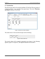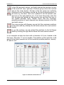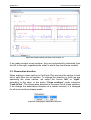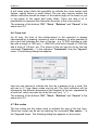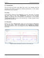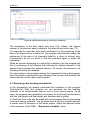
1
User’s manual
ConCrete Plus
BuildSoft n.v.
User’s manual ConCrete Plus
© BuildSoft nv
All rights reserved. No part of this document may be reproduced or
transmitted in any form or by any means, electronic or manual, for any
purpose whatsoever, without the prior written consent from BuildSoft.
The programs described in this manual are subject to copyright by
BuildSoft. They may only be used by the licensee and may only be copied
for the purpose of creating a security copy. It is prohibited by law to copy
them for any other purpose than the licensee’s own use.
Although BuildSoft has tested the programs described in this manual and
has reviewed this manual, they are delivered ‘As Is’, without any warranty
as to their quality, performance, merchantability or fitness for any particular
purpose. The entire risk as to the results and performance of the
programs, and as to the information contained in the manual, lies with the
end-user.
BuildSoft n.v.
User’s manual ConCrete Plus
TABLE OF CONTENTS
TABLE OF CONTENTS..............................................................................1
CHAPTER 1 INTRODUCTION..................................................................4
1.1. Required hardware ..................................................................................... 5
1.2. Installing ConCrete Plus ............................................................................ 5
1.3. ConCrete, the other modules .................................................................... 5
CHAPTER 2 A FIRST REINFORCEMENT PLAN ....................................6
2.1. Introduction ................................................................................................. 7
2.2. Opening a ConCrete-project ...................................................................... 9
2.3. Getting an element out of the ConCrete-project ................................... 10
2.4. Determining the diameters for longitudinal bars .................................. 11
2.4.1. The window "Diameter determination" ................................................... 11
2.4.2. Transposition of theoretical sections into bars ....................................... 12
2.4.3. Copying bars .......................................................................................... 15
2.4.4. Determination of bar lengths .................................................................. 16
2.5. Entering geometrical data ....................................................................... 18
2.6. Support characteristics ........................................................................... 20
CHAPTER 3 CROSS SECTIONS ...........................................................21
3.1. Creating cross sections ........................................................................... 22
3.2. Observation direction .............................................................................. 23
3.3. Removing cross sections ........................................................................ 24
CHAPTER 4 COMMENTS ON THE PLAN .............................................25
4.1. Introduction ............................................................................................... 26
4.2. Bar legend ................................................................................................. 26
4.3. Stirrups ...................................................................................................... 26
4.4. Bars ............................................................................................................ 28
4.5. Cross sections .......................................................................................... 29
4.6. Form text ................................................................................................... 31
4.7. Bar codes .................................................................................................. 31
CHAPTER 5 A PROPER REPRESENTATION.......................................33
5.1. Introduction ............................................................................................... 34
5.2. Defining your own styles ......................................................................... 34
Table of contents
1
BuildSoft n.v.
User’s manual ConCrete Plus
5.3. Selecting styles ........................................................................................ 35
5.4. Layer names .............................................................................................. 36
5.5. Setting the background colour ............................................................... 37
5.6. Positioning of the title frame ................................................................... 38
5.7. Positioning of the bar bending schedule ............................................... 38
5.8. Positioning of the title .............................................................................. 39
CHAPTER 6 UNITS AND PRECISION ...................................................40
6.1. Introduction ............................................................................................... 41
6.2. Units ........................................................................................................... 41
6.3. Precision.................................................................................................... 41
6.4. Possible combinations ............................................................................ 42
CHAPTER 7 MODIFYING THE REINFORCEMENT ...............................43
7.1. Bar tolerances ........................................................................................... 44
7.2. Continuous or discontinuous bars on supports ................................... 46
7.3. Curved or straight anchorage ................................................................. 47
7.4. Continuous or discontinuous anchorage .............................................. 47
7.5. Modifying bar lengths .............................................................................. 50
7.6. Entering web reinforcement .................................................................... 52
7.7. Maximum bar length ................................................................................. 54
7.8. Modifying the stirrups .............................................................................. 55
CHAPTER 8 AN ENTIRE PROJECT OF BEAMS ..................................58
8.1. Introduction ............................................................................................... 59
8.2. Defining classes ....................................................................................... 59
8.3. Getting an element out of a certain class .............................................. 60
8.4. Moving an element to another class....................................................... 60
8.5. Duplicating an element ............................................................................ 60
8.6. Deleting an element .................................................................................. 61
8.7. Copying elements between projects ...................................................... 61
CHAPTER 9 BAR BENDING SCHEDULE .............................................62
9.1. Automatic generation of bar bending schedule .................................... 63
9.2. Numbering of the bars ............................................................................. 63
9.3. Exporting a bar bending schedule file ................................................... 65
CHAPTER 10 PRINTING ........................................................................67
10.1. Page setup settings ................................................................................ 68
10.2. Setting the print options ........................................................................ 69
10.3. Printing an entire project ....................................................................... 71
Table of contents
2
BuildSoft n.v.
User’s manual ConCrete Plus
10.4. Printing an entire class .......................................................................... 71
10.5. Printing only one element ...................................................................... 71
CHAPTER 11 EXPORT TO CAD PROGRAMS ......................................72
11.1. Plot settings ............................................................................................ 73
11.1.1. File format ............................................................................................ 73
11.1.2. Plot font ................................................................................................ 73
11.1.3. Plot scale .............................................................................................. 75
11.3. Creating a plot file .................................................................................. 76
CHAPTER 12 SAVING, OPENING, CLOSING .......................................77
12.1. Opening an existing project .................................................................. 78
12.2. Saving an existing project ..................................................................... 78
12.3. Saving automatically .............................................................................. 78
12.4. Closing a project .................................................................................... 80
12.5. Editing the project data .......................................................................... 80
12.6. Quitting the program .............................................................................. 80
CHAPTER 13 USEFUL TIPS ..................................................................81
13.1. Calculate automatically or not .............................................................. 82
13.2. Automatic proposition for the reinforcement ...................................... 82
13.3. Sounds..................................................................................................... 82
13.4. Connections with ConCrete .................................................................. 83
13.5. Use of the arrow-keys ............................................................................ 84
13.6. Use of the "Edit"-menu .......................................................................... 84
13.7. Zoom in and out on the screen ............................................................. 84
13.8. Modifying the look and feel of ConCrete Plus ..................................... 85
CHAPTER 14 OVERVIEW OF THE MENUS ..........................................87
14.1. “File” - menu .......................................................................................... 88
14.2 “Edit” - menu............................................................................................ 88
14.3. “Element” - menu ................................................................................... 89
14.4. “Window” - menu ................................................................................... 89
14.5. “Lay-out” - menu .................................................................................... 89
14.6. “Preferences” - menu ............................................................................. 90
14.7. “Cross section” - menu ......................................................................... 91
14.8. “Help” - menu.......................................................................................... 92
Table of contents
3
BuildSoft n.v.
User’s manual ConCrete Plus
Chapter 1 Introduction
1. Introduction
4
BuildSoft n.v.
User’s manual ConCrete Plus
1.1. Required hardware
ConCrete is available for the operating systems Microsoft Windows 98,
NT, 2000, Millennium, XP, Vista or 7.
1.2. Installing ConCrete Plus
The software can be installed from CD-ROM or over the internet. In this
case, you should have a valid LOGIN and PASSWORD to access the
“Downloads” section of the BuildSoft website www.buildsoft.eu. BuildSoft
customers receive access to this protected section as part of their
maintenance or lease service contract. Other people interested in
evaluating ConCrete Plus receive valid access data for a 30-days period
provided they register at the BuildSoft web site.
The first time you install the program, you need to log on with appropriate
administration rights.
1.3. ConCrete, the other modules
ConCrete belongs to a package of 3 programs which together manage the
design process of reinforced concrete beams.
The ConCrete module automises the static and organic calculation of
continuous beams and slabs (in one direction) of reinforced concrete.
The ConCrete Plus module uses these results for generating the
reinforcement plans.
The ConCrete List module creates the bar bending schedules of the used
reinforcement steel.
ConCrete Plus can only be used for the generation of reinforcement plans
for elements prior calculated with ConCrete, Diamonds, PowerFrame of
PowerPlate.
1. Introduction
5
BuildSoft n.v.
User’s manual ConCrete Plus
Chapter 2 A first reinforcement plan
2. A first reinforcement plan
6
BuildSoft n.v.
User’s manual ConCrete Plus
2.1. Introduction
We will now get used to the working method of ConCrete Plus by means of
a simple example. Let us consider a two span beam. This is the "Structure
and loads"-window of ConCrete:
Figure 1: Structure and loads example 1
The load values of the second load type are the following:
Figure 2: Second load case
The actual values of the analysis parameters are shown in the following
figures (Figure 3 to Figure 6). The applied standard is Eurocode 2.
2. A first reinforcement plan
7
BuildSoft n.v.
User’s manual ConCrete Plus
Figure 3: Characteristics of the reinforcement
Figure 4: Characteristics of the concrete
2. A first reinforcement plan
8
BuildSoft n.v.
User’s manual ConCrete Plus
Figure 5: Moment reduction
Figure 6: Safety factors and combination factors
Create this beam in the ConCrete program and save the file.
2.2. Opening a ConCrete-project
As already mentioned before, we can only draw with ConCrete
Plus the reinforcement plans of elements calculated with
ConCrete, PowerFrame, PowerPlate or Diamonds. We cannot create a
new project with ConCrete Plus.
2. A first reinforcement plan
9
BuildSoft n.v.
User’s manual ConCrete Plus
After having started ConCrete Plus, select the first command "Open..." in
the menu "File" or click on the icon
in the icon bar. Select the saved
file in the dialog box to open it.
On the left side of the screen appears in the upper side a button palette
(Figure 7), while in the under side the Project list-window (Figure 8)
appears.
Figure 7: Palet
Figure 8: Project list
The Project list-window has the same function as in ConCrete.
2.3. Getting an element out of the ConCrete-project
Open the desired class by clicking on the +-sign or by double-clicking the
class name. The list of the beams belonging to this class appears below.
Double-click the first (and only) beam (see also chapter 8).
A window appears with the title “Reinforcement plan”. The window
contains 3 tab sheets. The first tab sheet “Main drawing” contains the
drawing of the complete beam. In the following tab sheets the drawings are
given per span.
2. A first reinforcement plan
10
BuildSoft n.v.
User’s manual ConCrete Plus
Figure 9: Reinforcement plan
You can access the reinforcement plan window at any time by clicking on
the icon
or by selecting the first command “Reinforcement plan” in
the menu “Window”.
At the bottom of the window, you find some functions to improve the
readability and handling of the plan. With the buttons
and
you can
zoom in and out, with the button
you draw a rectangle which you want
to be maximised. The other icons will be explained later on in this manual.
2.4. Determining the diameters for longitudinal bars
2.4.1. The window "Diameter determination"
In the window "Reinforcement plan" the longitudinal reinforcement is
missing. We determine this longitudinal reinforcement as follows.
Remark: When the option “Reinforce automatically” is checked in the
menu “Preferences”, than ConCrete Plus calculates a fitting
reinforcement proposition. Of course, you can change this proposition by a
proper choice as described in this section.
Select the second command "Diameter determination" in the menu
"Window" or click on
. A new window appears with the title "Diameter
determination" (Figure 10).
In the margins of this window, there are several buttons to improve the
readability of the content. Click e.g. on the button "x2" in the right margin
2. A first reinforcement plan
11
BuildSoft n.v.
User’s manual ConCrete Plus
through witch the vertical scale is doubled. This is what happens before
and after doubling the vertical scale:
Figure 10: Diameter determination
Figure 11: Diameter determination 2
The representation of the beam in Figure 11 is completely analogous with
the "Reinforcement sketch"-window from ConCrete.
The thick lines indicate where reinforcement is required. The ending points
of the thick lines are the locations of zero points of the bending moment.
Strictly taken, we do not require reinforcement there where the thin lines
are located. We will however always provide a minimum of longitudinal
reinforcement for constructive reasons. The theoretically required
reinforcement sections are indicated in outline in mm². The anchorage
sections are indicated just above the bottom reinforcement sections, there
where the supports are located. We will go on examining the matter later
on (see 7.4).
2.4.2. Transposition of theoretical sections into bars
In order to transfer a certain theoretical section into a number of bars, we
click with the mouse on the location of the number reflecting the theoretical
section.
We will first transfer the top reinforcement sections into bars and therefore
select the first top reinforcement section "86" left on top. This number is
2. A first reinforcement plan
12
BuildSoft n.v.
User’s manual ConCrete Plus
now framed and a dialog box appears on the screen to determine the
distribution of the bars :
Figure 12: Diameter determination
We enter the number of bars of a certain group of bars in the first
column,
in the second column, the diameter (in mm) of these bars and
in the third, the layer in which the bars are situated.
The fourth column is used for specifying the cut priorities by means
of the cut number. The bar groups with the lowest number are cut
off first. Different bar groups can of course have the same number ;
in that case they will be cut off at the same time. In practice it can
be useful to define bars with the same diameter in different bar
groups, in order to be able to cut them differently.
2. A first reinforcement plan
13
BuildSoft n.v.
User’s manual ConCrete Plus
In the fifth and sixth column, we finally indicate the position (in mm)
of the most left, resp. right bar of the bar group versus the vertical
axis of the cross section. All bars of the bar group are uniformly
distributed over the distance limited by the two entered positions. If
we have e.g. two bars, then one is placed in the left position (xb)
and one in the right position (xe); if we have three bars, then the
first two bars are placed as the previous two and the third one in
the middle between them. Please notice that the maximum
possible positions of each diameter are already entered in the fifth
and sixth column.
For cross section with flanges, we can limit the maximum positions
to the web width by clicking the left button above the cross section
sketch,
or, on the contrary, we can extend the positions to the full flange
width by clicking the right button above the cross section sketch.
In our example we take two bars with a diameter of 8 mm, located in the
first layer. We enter "1" as cut number. The position of the outer bar in the
group (of two bars) remains set at the maximum possible position, namely 41 and 41 mm:
Figure 13: Diameter determination 2
2. A first reinforcement plan
14
BuildSoft n.v.
User’s manual ConCrete Plus
When determining the number of diameters we can always check at the
bottom of the dialog box how much mm² reinforcement we have foreseen
and how much there is still to foresee. The reinforcement section of the
bars we place in another layer than the first layer, is automatically
calculated to an equivalent reinforcement section in the first layer. We have
placed sufficient bars when the reinforcement section that is still to be
foreseen, becomes less than the imposed tolerance (see 7.1) . A negative
value indicates the surplus of mm² reinforcement versus the theoretically
required section.
We confirm our choice by pressing the "OK" button. The
indication "2 ø 8" is now above the earlier selected "86" in the
"Diameter determination"-window ; this leads to the
conclusion that we have indeed entered two bars with a diameter
of 8 mm (Figure 14). The number "86" is now no longer indicated
in italic.
Figure 14: Diameter determination after first input
Transfer in an analogous way the second top reinforcement section into
two bars of diameter 20 mm.
2.4.3. Copying bars
We also wish to foresee two bars with a diameter of 20 mm for the third top
reinforcement section. We can do so by applying the same working method
as in 2.4.2. There is however a quicker way. We can copy the bars we
have defined for the previous section to the section to be converted in the
following way.
Instead of immediately selecting the section to be converted, we first press
the shift-key and keep it pressed when selecting the meant section with
the mouse.
No dialog window appears on the screen, but the bars of the previous
section are immediately copied to the selected section. We can notice this
by means of a different cursor :
2. A first reinforcement plan
15
BuildSoft n.v.
User’s manual ConCrete Plus
Figure 15: Cursor for copying bars
This cursor inform us that the bars of the previous section are copied.
If we want to copy the bars of the next section we apply the same working
method only now we press the control-key instead of the shift-key. The
little hand now points to the right, in other words, to the next section.
Figure 16: Diameter determination after copying bars
2.4.4. Determination of bar lengths
We transfer all the reinforcement sections to the reinforcement bars using
the working method explained in 2.4.2 and 2.4.3 (Figure 17). Once this
transfer is finished, ConCrete Plus automatically calculates the lengths of
the different bars and completes the window "Reinforcement plan"
(Figure 18).
Figure 17: Diameter determination with top reinforcement ok
2. A first reinforcement plan
16
BuildSoft n.v.
User’s manual ConCrete Plus
Figure 18: Reinforcement plan with top reinforcement ok
If we apply the same working method to determine the bottom
reinforcement bars, we get a first reinforcement plan (Figure 19).
Figure 19: A first reinforcement plan
If one practical bar choice can be applied for the whole beam (i.e. for all
spans), this can be realised by clicking in the dialog box for the diameter
determination on the button "OK for all" instead of on the button "OK".
This spares you from copying bars. Note that by indicating different cut
numbers certain bars are only put where needed. ConCrete Plus detect
these places itself.
In the same way, by means of the button “OK for span”, you can apply a
bar choice (for bottom or top reinforcement) to all the sections of the
selected span.
2. A first reinforcement plan
17
BuildSoft n.v.
User’s manual ConCrete Plus
2.5. Entering geometrical data
We saw in ConCrete that we could set a certain tolerance for the
difference in dimensions between the drawing in ConCrete Plus versus
the calculation. Through the command “Dimension tolerances” in the
menu “Preferences” we can call again this dialog box.
Figure 20: Tolerances between ConCrete and ConCrete Plus
Let us assume that we had set this tolerance in ConCrete at 1 cm; we can
now modify the dimensions of the span lengths and zone lengths is
ConCrete Plus 1 cm versus the values in ConCrete. A recalculation of the
bar lengths and stirrup zones is done automatically and the determining
diagrams are flattened in the length. The vertical values are not flattened
(the values of the statical quantities). When changing the span length, the
distance between the supports is also modified.
We can easily modify a span- or zone length by selecting that value with
the mouse in the window "Reinforcement plan". This value appears in the
input bar with the belonging question. We can now enter a new value by
means of the keyboard and confirm this value with the ENTER- or
RETURN-key. Only values within the set tolerance are accepted.
Figure 21: Input of span length
Except for the span- and zone lengths, we can also modify the width of
the supports (drawn as columns). For each new element that has to be
drawn, ConCrete takes a width of 19 cm for each support. We can change
this value freely in an analogous way as the span- and zone lengths. Half
the width of a support cannot exceed the half of a span.
All supports are placed symmetrically versus the axes which determine the
span lengths, except for the end supports. End supports can be placed
2. A first reinforcement plan
18
BuildSoft n.v.
User’s manual ConCrete Plus
asymmetrically and their position is in consequence determined by two
values: the width on the left hand side of the end axis and the width on the
right hand side of that axis. If we change the wide of a support, the
program automatically recalculates the different bar lengths and
redistributes the stirrups between the supports.
When placing the stirrups, the first and the last stirrup zones of a span are
decreased in length according to the width of the support. We however
notice that no complete recalculation takes place which redetermines the
first shear force crack, starting from the width of the support and out of that
calculates new distances and diameters from the stirrups. Fundamental
calculations take place in ConCrete and not in ConCrete Plus.
Practically seen the working method used here has the same result as a
complete recalculation when the length, across which the stirrup distance
is kept constant, approximates half the width of the column. As this length
deviates from this width, the used working method may give a slightly
different result, which is however at least as safe.
If we modify in our example the span lengths of 4.00 m to 4.01 m, and
bring the width of the intermediate support to 60 cm, our reinforcement
plan looks as visualised in Figure 22.
We notice that the program automatically selects the next value after we
have changed a certain value. This means that we can quickly change the
different data.
Figure 22: Reinforcement plan after modifying geometry
2. A first reinforcement plan
19
BuildSoft n.v.
User’s manual ConCrete Plus
2.6. Support characteristics
Click with the right mouse button in the window "Reinforcement plan" to
open the dialog box "Support characteristics". In this dialog box a
number of characteristics of the different supports can be modified.
In the upper part of the dialog box, the dimensions of the supports as
drawn in ConCrete Plus are represented. Here you can also change the
vertical dimensions of the supports.
Further on, you can decide whether the support will be executed as a direct
support or more as an indirect one (the reaction does not directly go to the
foundation, e.g. the support is a beam). Is it a direct support, than the
anchorage lengths of the bars will be reduced with a factor 2/3.
Finally, there is an option to continue the transverse reinforcement (stirrups
and web reinforcement) to the axis of the support.
Figure 23: Support characteristics
2. A first reinforcement plan
20
BuildSoft n.v.
User’s manual ConCrete Plus
Chapter 3 Cross sections
3. Cross sections
21
BuildSoft n.v.
User’s manual ConCrete Plus
3.1. Creating cross sections
So far we have represented our beam only in longitudinal view. In practice
we will also make a certain number of cross sections over the length of the
beam, to illustrate the position of the bars in the cross section. In ConCrete
Plus the maximum number of cross sections per element is 26. The
position of the cross sections can be chosen freely over the length of the
beam, knowing that we cannot make a cross section that goes through a
support.
We use the following working method in order to make a cross section. We
click with the mouse in the bottom left corner of the window
"Reinforcement plan" ( ).We then move the mouse over the front view
of the beam. When moving the mouse, we see a vertical line that follows
the position of the mouse appearing in the window. Note that cursor
changes when the position allows a cross section or not.
Click on the position where you want to have a cross section and
ConCrete Plus automatically generates a cross section through the beam
at the position of the vertical line. The drawing of the cross section appears
beneath the longitudinal view (Figure 24).
The position of the stirrups and the longitudinal bars and the dimensions of
the beam are indicated on this cross section. It is important to know that
these cross sections are adapted each time there is a modification in the
reinforcement.
3. Cross sections
22
BuildSoft n.v.
User’s manual ConCrete Plus
Figure 24: Reinforcement plan with cross section 1-1
If we make several cross sections, they are automatically numbered from
the left to the right, regardless the order in which they have been created.
3.2. Observation direction
When making a cross section in ConCrete Plus we have the choice to look
left of right from the set position. To change the direction in chich we are
observing the cross section, we select the choice 'left" or "right",
according to the case, in the menu "Cross sections" under submenu
"Look to the". The observation direction is the same for all cross sections.
If we change the observation direction at a certain moment, it is changed
for all cross sections already made.
Figure 25: Changing the observation direction
3. Cross sections
23
BuildSoft n.v.
User’s manual ConCrete Plus
3.3. Removing cross sections
If we wish to remove a certain cross section, we select its number in the
menu "Cross section" under submenu "Remove.
Figure 26: Removing a cross section
The program removes the selected cross section and adjusts the
numbering of the following sections.
Cross sections are automatically removed by the program when, at a
certain moment, their position exceeds the length of the element or is
within the measurements of a support. This can happen when the width of
a support or the length of a span or a zone is changed.
3. Cross sections
24
BuildSoft n.v.
User’s manual ConCrete Plus
Chapter 4 Comments on the plan
4. Comments on the plan
25
BuildSoft n.v.
User’s manual ConCrete Plus
4.1. Introduction
So far we did not care about the text and explanation that the program
automatically places with the drawing. In practice, each engineering office
has its own way of making representations. Therefore ConCrete Plus has
been provided with various possibilities to clarify the drawing with the
necessary information. In this chapter we will learn how to determine what
information is placed at what location on the plan.
4.2. Bar legend
The symbol to use for indicating the bar diameter can be set by the
command “Bar legend” under the submenu “Comments” in the “Layout” menu.
Figure 27: Bar legend
In the third option ‘other’ the use can define the symbol by himself.
4.3. Stirrups
If we wish to change the information of the stirrups in longitudinal view, we
select the first command "Stirrups…"in the menu "Lay-out" under the
second submenu "Comments". The dialog box of Figure 28 is now
visualised on the screen.
We can indicate by means of a check box whether or not we want the
stirrups to be drawn in the longitudinal view. With the pull down menu we
can indicate how many stirrups should be drawn per zone. We have
different choices:
- drawing all stirrups
- drawing 1 stirrup per zone (in the middle of the zone)
- drawing 2 stirrups per zone (one at the beginning and one at the end
of each zone)
4. Comments on the plan
26
BuildSoft n.v.
User’s manual ConCrete Plus
- drawing 3 stirrups per zone (one at the beginning, one in the middle
and one at the end of each zone)
In the square left on top we can indicate by means of four radio buttons to
what line (related to the dimensioning line) we wish to give what
information. The different possibilities for this information are indicated in
the big rectangle on the right. We change the information on the indicated
line by selecting another radio button in the right rectangle.
Figure 28: Stirrups
The theoretical distance is the distance between the stirrups as it was
calculated by ConCrete, in other words without taking into account whether
the total distance is a multiple of the distances. The real distance is the
distance we obtain by dividing the length along which the theoretical
distance is valid, by the number of stirrups.
With the last but one radio button we can let the program draw vertical
lines on the desired line, at the place of the horizontal position of the
stirrups.
In the edit field at the left bottom side, we can enter an alternative for
“each”.
The meaning of the buttons "OK", "Store", "Retrieve" and "Cancel" is
similar to the signification in ConCrete. Actual settings are confirmed by
pressing the "OK" button. They can be set as standard settings by
pressing the "Store" button. If the actual settings are different from the
4. Comments on the plan
27
BuildSoft n.v.
User’s manual ConCrete Plus
standard settings, they can be set equal to the standard settings by
pressing the "Retrieve" button. The button "Cancel" does not change the
actual settings. The standard settings are saved when ending the program.
When starting the program, the standard settings are drawn up and
immediately become the actual settings.
For the explanation of "[Form text]" we refer to 4.6.
Figure 29: Reinforcement plan with alternative stirrup comment
If we e.g. change the information on the second line to the first information
choice (with the first radio button), our reinforcement plan looks as
visualised in Figure 29.
Font type, font size and the number of the layer on which the information
will be placed in general CAD sofware are set by selecting the fourth
command "Stirrups…" in the menu "Lay-out" under the first submenu
"Representation" (see 5.5).
4.4. Bars
We select the second command "Bars…" in the menu "Lay-out" under the
submenu "Comments" if we wish to modify the information of the bars in
the longitudinal view. The following dialog box now appears on the screen:
4. Comments on the plan
28
BuildSoft n.v.
User’s manual ConCrete Plus
Figure 30: Bars
We can indicate by means of three radio buttons how we wish to represent
the end of a bar when several bars overlap one another. Furthermore, we
can also indicate what information we wish to add to those bars. For the
determination of the style, we refer to chapter 5.
The meaning of the buttons "OK", "Store", "Retrieve" and "Cancel" is the
same as in 4.3.
For the explanation of "[Form text]" we refer to 4.6.
4.5. Cross sections
We select the fourth command "Cross sections…" in the menu "Lay-out"
under the submenu "Comments" if we wish to modify the information of
the bars and the stirrups in the cross sections. The following dialog box is
now visualised on the screen:
4. Comments on the plan
29
BuildSoft n.v.
User’s manual ConCrete Plus
Figure 31: Cross sections
Indicate just like in 4.3 and 4.4, which information should be placed on the
plan. The buttons under "Text bars" and "Text stirrups" serve for whether
or not using indication lines to the bar or to the stirrup. The choice
possibilities for the information are analogous to those for the longitudinal
view.
By clicking on one of the cross section representations at the top of the
dialog box, we can change the representation of the cross section. We can
choose between an indication of the reinforcement according to the
position in the cross section (whether or not with indication lines) or an
indication of the reinforcement by placing the number of the list
immediately with the cross section drawing and a list next to it with in order
the numbers of the list and their belonging information. The cross section
drawing looks as visualised below if we choose the first possibility:
Figure 32: Cross section 1 alternative representation
4. Comments on the plan
30
BuildSoft n.v.
User’s manual ConCrete Plus
A pull down menu offers the possibility to indicate the cross section with
figures, capital letters or small letters. We can also choose wether the
section indication should be drawn of the whole height of the beam or just
in the region of the upper and lower fibres. There are also a lot of
possibilities to represent the obervation direction of the cross section.
The meaning of the buttons "OK", "Store", "Retrieve" and "Cancel" is the
same as in 4.3.
4.6. Form text
Up till now, the form of the reinforcement in the comment is always
represented by a drawing. Instead of such a drawing, it’s also possible to
put a text that indicates the form of the bar : e.g. R 1500 indicates a right
bar with a length of 1500 mm, L 140x1500 a bar with a length of 1500 mm
and a hook of 140 mm, etc. The choice of the text can be set by the last
command "Form text…" in the submenu "Comments" from the “Lay-out”
menu. The following dialog box appears:
Figure 33: Form text
Here we can choose to indicate the form by a drawing or by a code. We
will see in 4.7 how these codes can be set. The form indication will be
followed by the different dimensions (fold lengths) of the bar, separated by
a fixed text, which can also be set by the user (e.g. " x ").
The meaning of the buttons "OK", "Store", "Retrieve" and "Cancel" is the
same as in 4.3.
4.7. Bar codes
The bar codes are the codes used to indicate the type of the bar form.
These bar codes can be set by selecting the command "Bar codes…" in
the "Lay-out" menu. The following dialog box appears on the screen:
4. Comments on the plan
31
BuildSoft n.v.
User’s manual ConCrete Plus
Figure 34: Bar codes
In this form you can indicate which code to use for which form. Select a
form and type the desired code in the edit box. The bar codes have no
restrictions. One bar code be used for different forms. The sequence of the
dimensions in the form text (see 4.6) corresponds to the alphabetical order
of the with letters named fold lengths.
The meaning of the buttons "OK", "Store", "Retrieve" and "Cancel" is the
same as in 4.3.
4. Comments on the plan
32
BuildSoft n.v.
User’s manual ConCrete Plus
Chapter 5 A proper representation
5. A proper representation
33
BuildSoft n.v.
User’s manual ConCrete Plus
5.1. Introduction
We now already know how to generate a plan from a beam calculated with
ConCrete and how to add the desired information. Of course we do not
only want to determine what information we wish to add to the plan, but
also how we will represent that plan. In this chapter we will learn how to
indicate for each kind of line a proper thickness, type, colour and
dimensioning.
5.2. Defining your own styles
In ConCrete Plus at maximum 30 styles can be defined. Select the first
command "Style definition…" in the “Lay-out” menu; the following dialog
box appears on the screen :
Figure 35: Style definition
Each style has its own properties. In the list at the left are the names of all
defined styles. At the right, the properties of the selected style are shown;
here for style "STYLE1".
Each style is characterised by a certain colour, pen width and line type.
The choosen characteristics are framed. Here the colour of STYLE1 is
black, the pen width a thin line and the line type a dot-dash-dot. With a pull
down menu, the layer (see 5.4) can be choosen on which elements drawn
in this style will be put. This layer will also be used by the transfer (e.g. by
DXF) to a generalised CAD-program.
5. A proper representation
34
BuildSoft n.v.
User’s manual ConCrete Plus
End marks can be an arrow or an inclined dash; these can be the end
marks from a dimensioning line or from a reference line to the comment to
reinforcement elements.
Finally, you can define the font type and font size. The font size is used
within ConCrete Plus, but is also used for direct printing and for the
transfer (e.g. in DXF) to other CAD programs. For this transfer, the font
size will correspond only if the same scale is used in the CAD program as
the one that was set in ConCrete Plus (see 11.1.3). When another scale is
used, the font sizes will be adapted with the same proportion.
Styles which are not used by any element, can be removed by selecting
them in the list and clicking on the button "Remove".
The name of the style can be changed by entering a new name in the edit
box beneath the list and then clicking on the button "Rename…".
As long as the number of defined styles is less than 30, new styles can be
added by typing a new name in the edit box and clicking on the button
"New…".
The meaning of the buttons "OK", "Store", "Retrieve" and "Cancel" is the
same as in 4.3.
5.3. Selecting styles
The next step is to assign elements to the dedicated styles.
Select the second command "Style choice…" in the “Lay-out” menu. The
following dialog box appears on the screen:
5. A proper representation
35
BuildSoft n.v.
User’s manual ConCrete Plus
Figure 36: Style choice
With the help of pull down menus, you can assign a style to the different
elements in the drawing. In these pull down menus, only the styles defined
in 5.2 are listed.
With "hidden geometry" the flanges who are at the backside of the beam
are meant. The "numbers next to element" are the numbers that are put
at the begin- and endpoint in the longitudinal view and the number that are
put by the reinforcement elements in the cross section when the
representation with the list is chosen (see 4.5). For the meaning of the title
box, we refer to 10.1.
To represent all reinforcement numbers in the same style, there’s the
option "numbers in comments other style".
For the meaning of the buttons "OK", "Store", "Retrieve" and "Cancel" we
refer to 4.3.
5.4. Layer names
To included drawings of ConCrete Plus in a generalised CAD program, it’s
not only important to use the same representation (style), but also it’s the
best to use the same layer names.
To be able to define these layer names, select the fourth command "Layer
names…" in the “Lay-out” menu. The following dialog box appears on the
screen:
5. A proper representation
36
BuildSoft n.v.
User’s manual ConCrete Plus
Figure 37: Layer names
In the list at the left are the names of all defined layers. When you select a
layer in this list, the name will be put in the edit box.
You can change the name of the layer, by changing the name in this edit
box and clicking on the button "Modify".
To add a new layer, just type the name of the new layer in the edit box and
click on the button "Add"; the layer that was selected will keep its name.
The number of layers is restricted to 50. All letters will be automatically
translated into capital letters.
If a layer is no longer needed (in other words there is no style defined that
uses this layer) , this layer can be removed by selecting it in the list and
clicking on the button "Remove...".
5.5. Setting the background colour
To change the
"Background…":
5. A proper representation
background
colour,
select
the
third
command
37
BuildSoft n.v.
User’s manual ConCrete Plus
Figure 38: Background colour
5.6. Positioning of the title frame
The position of the title frame with the administrative data can be defined.
In the submenu “Title frame position” of het “Lay-out” menu, you can
choose between “left” of “right”. The title frame is always set at the bottom
of the plan.
Figure 39: Setting the title frame position
5.7. Positioning of the bar bending schedule
The position of the bar bending schedule on the plan can be set by the
command “Lay-out” - “position of the bar bending schedule”. You can
align the list with the top or the bottom of the plan.
5. A proper representation
38
BuildSoft n.v.
User’s manual ConCrete Plus
Figure 40: Setting the Bar bending schedule of the bar bending schedule
5.8. Positioning of the title
Under the submenu "Title position" of the “Lay-out” menu, you can
indicate the desired position of the beam name (= title) in relation to the
longitudinal view. You can put it at the left top, right top or centre top.
Figure 41: Setting the title position
5. A proper representation
39
BuildSoft n.v.
User’s manual ConCrete Plus
Chapter 6 Units and precision
6. Units and precision
40
BuildSoft n.v.
User’s manual ConCrete Plus
6.1. Introduction
So far we did not care much about the units of our drawing and the
precision with which we indicate the different dimensions. In this chapter
we will learn how to set both.
6.2. Units
ConCrete Plus offers you the possibility to set our own units. To change
the units, select in the menu "Preferences" under the first submenu
"Units" the desired units. Automatically, all dimensions in the window
"Reinforcement plan" are set in the selected unit. It doesn’t matter at what
moment the units are set.
6.3. Precision
Select in the menu "Preferences" under the second submenu "Precision"
the desired option. Again, all dimensions are automatically adapted.
Setting the precision to mm, will change the window "Reinforcement plan"
as follows:
Figure 42: Reinforcement plan with precision in mm instead of cm
6. Units and precision
41
BuildSoft n.v.
User’s manual ConCrete Plus
6.4. Possible combinations
The possible choices for the units are m, cm and mm; for the precision the
units are cm and mm. It is however not possible to combine each unit with
each precision. The possible combinations are indicated in table 1.
Unit
m
Precision
cm
mm
cm
mm
mm
cm
mm
table 1
6. Units and precision
42
BuildSoft n.v.
User’s manual ConCrete Plus
Chapter 7 Modifying the reinforcement
7. Modifying the reinforcement
43
BuildSoft n.v.
User’s manual ConCrete Plus
7.1. Bar tolerances
Suppose that the units and accuracy are set to cm. In that case all rod
lengths are presented in cm and up to 1 cm accuracy.
In practice, bar lengths will be a multiple of 5 cm for example. Units and
accuracy remain determined to cm. Select in the menu "Preferences" the
last command "Bar tolerances ..." to make the length of the bars a
multiple of 5 cm. The screen displays the following dialog:
Figure 43: Bar tolerances
Enter in the dialog box the unit distance for the bar lengths and their
distance to the nearest axis. Enter also the minimum intermediate length
between two parts of a bar. Gaps smaller than the given value will not be
cut out.
Further on, the maximum deviation to theoretical required reinforcement
section can be set, either by a maximum absolute value or by a maximum
relative value (percentage). These maximum deviation is only checked for
values lower than the required value. Suppose that we need a theoretical
reinforcement amount of 406 mm². In practice, we would provide e.g. 2
bars Ø 16 (= 402 mm²). Strictly speaking, those 2 bars Ø 16 are
insufficient. By setting a maximum deviation, we can force the program to
accept it as sufficient.
Also the minimum transverse distance can be set. Anyway, the program
will always check that the centre-to-centre distance of bars is at least twice
the diameter (net distance = diameter).
Strictly speaking, it is not allowed that the support widths be less than the
values that follow from the required anchorage lengths from the bars that
are anchored in the support. Because this anchorage length is at the
7. Modifying the reinforcement
44
BuildSoft n.v.
User’s manual ConCrete Plus
minimum 10 Ø, possibly reduced by a factor 2/3 for direct supports, this
means that bars Ø 25 can’t be anchored on a support with a width of
19 cm. Since this, according to Eurocode 2 "practical", rule in practice
seems to be rather unpractical, ConCrete Plus allows you to just get a
warning that the support should be wider, but the program will however
generate the reinforcement drawing. Note that the acceptance of a smaller
support width is not strictly allowed by Eurocode 2! Even more, these
warnings can be eliminated by checking the checkbox, to avoid annoying
messages that decreases the productivity.
Enter 5 cm as unit length for the bar length and 1 cm for the unit distance
to the nearest axis. Confirm with the "OK"-button. ConCrete Plus
recalculates automatically the bar lengths. To get the theoretical required
bar length again, see 7.5.
Figure 44: Reinforcement plan – bar tolerances changed
When rounding bar lengths to a multiple of 5 cm, the bars lengths are
increased till the first multiple of 5 cm, unless the theoretical length is not
more than 2 mm bigger than the previous multiple. In case the bars need
to be extended, they are, as far as possible, as much extended to the left
as to the right.
Bars which are not a multiple of the indicated unit length and which cannot
be extended sufficiently, because otherwise they would not have sufficient
concrete cover or, worse, would exceed the element, are not extended at
all.
For the meaning of the buttons "OK", “Store”, “Retrieve” and "Cancel" we
refer to 4.3.
7. Modifying the reinforcement
45
BuildSoft n.v.
User’s manual ConCrete Plus
7.2. Continuous or discontinuous bars on supports
In practice it is often interesting not to let the bars continue over the entire
beam length, but to consider them per span (think about prefabrication). In
ConCrete Plus we can indicate as well for the bottom – as for the top
reinforcement whether of not the bars on the supports can continue.
Figure 45: Continuous or discontinuous bars on supports
Click with the Mouse in the pallet on the button until the desired option
appears, e.g. (top reinforcement) ‘continuous’. ConCrete Plus
automatically recalculates the top reinforcement and the bars (2) and (3) of
Figure 43 are replaced by one bar (2). The numbering of the other bars is
automatically adapted. The reinforcement drawing now looks asfollows:
Figure 46: Longitudinal view continuous reinforcement
In case of continuous bottom reinforcement on the supports, we select the
second button and use the same working method as for the top
reinforcement
7. Modifying the reinforcement
46
BuildSoft n.v.
User’s manual ConCrete Plus
7.3. Curved or straight anchorage
ConCrete Plus gives you the possibility to apply a straight or curved
anchorage (hook) on the supports. There are three possibilities (Figure
47):
- all bars are anchored with a hook, unless the horizontal
anchorage length is as big as the length required for straight
anchorage;
- all bars are as far as possible anchored straight ; only when the
bar exceeds the measurements of the concrete, a curved
anchorage is applied;
- only bars that exceed the axis of the column, are anchored
curved, unless the horizontal anchorage length of the hook is as
big as the length required for straight anchorage.
Figure 47: Curved or straight anchorage
We can set the top reinforcement via the third button of the pallet, and set
the bottom reinforcement via the fourth button. ConCrete Plus
automatically recalculates and redraws the different bars for each
modification.
The moment at which this choice is determined is of no importance. Please
notice that we always see the set choices represented in the pallet.
7.4. Continuous or discontinuous anchorage
In 7.2. we have pointed out that it is often interesting for prefabrication
purposes to keep the bottom reinforcement separate per span. There is
however a second problem for prefabrication, viz. the presence of
numerous reinforcement bars at the place of the nodes with the columns
hinders the casting of the node or even make it practically impossible. A
7. Modifying the reinforcement
47
BuildSoft n.v.
User’s manual ConCrete Plus
fitting solution to solve this problem is to keep the anchorage reinforcement
as limited as possible by means of discontinuous anchorage.
This means that the foreseen bottom reinforcement of the different spans
is nowhere within the dimensions of the column and that we place extra
anchorage bars, mostly a little more centred in the cross section (nearer
to the section axis) and possibly in the second layer, to avoid conflicts with
other bars.
These anchorage bars are of course within the dimensions of the columns
and take care of the anchorage in the columns on the one hand and of the
transfer to the bottom reinforcement in the span on the other. As already
mentioned in 2.4.1, the required sections for these anchorage bars, the socalled anchorage sections, are indicated in the window "Diameter
determination" there where the supports are located, just above the
bottom reinforcement sections. We use the same working method as
described in 2.4.2, to transform these sections into bars.
We transform the theoretical anchorage sections into bars as in
. Use the button "OK for all" to validate this choice for all anchorage
sections.
7. Modifying the reinforcement
48
BuildSoft n.v.
User’s manual ConCrete Plus
Figure 48: Anchorage bars
Figure 49: Continuous or discontinuous anchorage
If we select the option "discontinuous anchorage" (Figure 49) via the fifth
button in the pallet; ConCrete Plus automatically recalculates the bottom
reinforcement.
When recalculating, the program tells us that the required width for the first
and the third support is 243 mm. We can explain the higher required width
as follows; The continuous anchorage was assured by two bars with a
diameter of 16 mm, while the discontinuous anchorage now takes place by
means of two bars of 12 mm and in the second layer. The foreseen
anchorage section is significantly lower. Precisely because of this smaller
anchorage section, we require a larger anchorage length.
The anchorage length in our example is too big to let the anchorage bar
fall within the width of the support. Because of the reason mentioned in
7.1, the program nevertheless draws the bottom reinforcement, with, in
7. Modifying the reinforcement
49
BuildSoft n.v.
User’s manual ConCrete Plus
principle, too small anchorage lengths. Therefore we enlarge the outer half
width of the end supports to 20 cm.
After automatical recalculation our plan looks as follows:
Figure 50: Longitudinal view discontinuous anchorage
7.5. Modifying bar lengths
So far we saw how to transform the theoretical reinforcement section into
bars and how to tell the program how we wish to determine the bar
lengths. The calculation and drawing of the bar lengths is done
automatically by the program.
In 7.1 we saw how to determine the different bar lengths in a more
practical way. This result may in some cases still deviate from what we
actually want. Think e.g. about the anchorage on the supports, which the
program always assumes straight when the horizontal length required for a
hook is as big as the anchorage length for a straight bar. In such a case
however, many engineering offices will still add a hook to the anchorage,
although it is not strictly required.
If we wish to change the measurements of a bar, we click with the mouse
in the window "Reinforcement plan" there where the information of that
bar is situated. As an example we will foresee the bars (7) and (8) of a
vertical hook with a length of 15 cm.
After clicking with the mouse on the concerned information, the following
dialog box appears on the screen:
7. Modifying the reinforcement
50
BuildSoft n.v.
User’s manual ConCrete Plus
Figure 51: Modifying bar lengths
In this window we can change the set measurements as we please. It is
obvious that the program never allows to choose measurements that are
smaller then theoretically required ones.
The two outer edit boxes on the left and the right serve to enter the vertical
length of the left-, respectively right hook. We can enter the total horizontal
length of the bar in the central edit box. If it differs from the theoretically
required length, the bar is, as much as possible, extended symmetrically.
In the two bottom edit boxes we can indicate the distance between the leftrespectively right ending point of the bar versus the left end of the beam.
Finally we can indicate for both hooks which is the angle with the
longitudinal direction of the bar.
Centrally at the bottom there is a button "Calculated values" with which
we can withdraw at any time the theoretically required bar length.
7. Modifying the reinforcement
51
BuildSoft n.v.
User’s manual ConCrete Plus
Figure 52: Adding hook lengths to bars
For bar (7) we enter the desired vertical hook of 15 cm (Figure 52) and
confirm our choice by pressing the "OK"-button. After applying the same
working method for bar (8), our reinforcement plan looks like this:
Figure 53: Reinforcement plan with changed bar lengths
7.6. Entering web reinforcement
Higher beams are usually equipped with web reinforcement. To determine
this web reinforcement, it’s sufficient to define the maximum vertical
distance between two successive layers. So, select “Web reinforcement”
in the menu "Preferences". The screen displays the following dialog:
7. Modifying the reinforcement
52
BuildSoft n.v.
User’s manual ConCrete Plus
Figure 54: Web Reinforcement
Set the "Max. vert. space between bars" for example on 20cm. This is
the height of the bar divided by 2. Click "OK". As shown in the figure below
ConCrete Plus shows that web reinforcement should be used.
Figure 55: The web reinforment suggested by ConCrete Plus
Like the bars of the longitudinal reinforcement, this bars can be changed at
any time by clicking on the appropriate text in the "Reinforcement Plan".
For bar 14 this gives:
7. Modifying the reinforcement
53
BuildSoft n.v.
User’s manual ConCrete Plus
Figure 56: Editing the web reinforcement
By clicking the button “OK for all” the distance from start and end points of
the web reinforcement to the column axis will be all taken the same. The
vertical position is adjusted along.
7.7. Maximum bar length
Selection in the menu “Preferences” the option “Maximum bar lengths”
to set the maximum bars lengths. For each diameter a different maximum
lengths can be defined.
Bars for with the theoretical length exceeds the maximum bar length, will
be split automatically. The lap length and anchorage length are also taken
into account.
Figure 57: Maximum bar length
7. Modifying the reinforcement
54
BuildSoft n.v.
User’s manual ConCrete Plus
7.8. Modifying the stirrups
Select in the menu “Preferences” the option “Stirrups” to change the
properties of the stirrups.
Figure 58: Properties of the stirrups
The option “multiple stirrups : different dimensions” allows you to use
non-identical stirrups in the section.
Figure 59: Multiple stirrups
Figure 60: Multiple stirrups
with identical dimensions
with different dimensions
Click with the mouse on the text accompanying the stirrups in the
"Reinforcement plan" window to modify the shape or to add a shape. On
the screen appears the dialog box of Figure 62.
In this window, first of all we see the number of shapes per section for the
stirrups. All these shapes are represented in the section sketch.
7. Modifying the reinforcement
55
BuildSoft n.v.
User’s manual ConCrete Plus
Select a stirrup form to modify it. The selection is done by choosing the
corresponding number in the pull down menu; the selected stirrup form is
always represented with a thick line in the section sketch. With each
selected shape corresponds a shape type, an insertion point (x0, y0), a
rotation angle around the insertion point, and the folding lengths a, b, etc.
On the sketch of the shape type the different folding lengths are indicated
and the insertion point is marked with a red dot. To modify folding lengths
and insertion point, you can edit the new values in the edit boxes.
The rotation angle can be modified by a pull down menu.
To modify the shape type of the stirrup, click on the button with the shape.
On the screen appears the dialog box of Figure 63.
Figure 61: Shape type button
Figure 62: Stirrups forms
7. Modifying the reinforcement
56
BuildSoft n.v.
User’s manual ConCrete Plus
Figure 63: Choose stirrup form
Click in this window on the desired shape and confirm with the "OK"
button.
By means of the buttons “OK for all” and “OK for span” the same stirrup
form will be applied to the whole beam, resp. the whole span.
Click in the dialog box of Figure 62 on the button "Add" to add an extra
stirrup in the section. Again the dialog box of Figure 63 appears. After
selecting the desired shape for the new stirrup, the number of stirrup forms
in
is increased by 1. The last added form is automatically selected, in the way
that we immediately can enter the insertion point, rotation angle and
folding lengths. The added stirrup has the same diameter and longitudinal
distance as the already present form(s). The form is only added in the
selected stirrup zone.
Each time you click on the wizard-button
, ConCrete Plus proposes
you an alternative logical shape for the stirrup.
7. Modifying the reinforcement
57
BuildSoft n.v.
User’s manual ConCrete Plus
Added stirrup shapes can be removed by selecting the shape and click on
the button "Remove". Of course, the shapes required by the calculation
can’t be removed.
7. Modifying the reinforcement
58
BuildSoft n.v.
User’s manual ConCrete Plus
Chapter 8 An entire project of beams
8. An entire project of beams
59
BuildSoft n.v.
User’s manual ConCrete Plus
8.1. Introduction
Projects made with ConCrete, almost consists of different classes with
different beams. In chapter 6 in the user’s manual of ConCrete is explained
how to create these classes and which operations can be done. We will
repeat briefly most of the operations here. For more information we refer to
the user’s manual of ConCrete.
8.2. Defining classes
Although the classes of our project were already defined in ConCrete, we
still can change these in ConCrete Plus. Select the latest command "List
of classes…" in the "Edit" menu. On the screen appears the following
dialog box:
Figure 64: List of classes
There’s a list with all the names of the classes. Like explained in the user’s
manual of ConCrete, we can rename, add and remove classes.
The button "Rename" is only enabled when there is a class selected in the
list and when the name of that class is modified in the edit box below the
list. Pressing this button will change the name in the list.
The button "Add" allows you do add new classes. The selected class and
all sequent classes will move one position down and a new class will be
inserted with the name in the edit box below the list.
The button "Remove" is only enabled when there is a class selected in the
list. With this button, not only the name of the class is removed out of the
list, but also all elements that belonged to this class.
8. An entire project of beams
60
BuildSoft n.v.
User’s manual ConCrete Plus
Note that the position of the class in the list can be easily changed. First
select the class you want to move. Keep the mouse button pressed and
move the class in the list to the desired position. Release the Mouse button
and the class is move to its new position.
We notice that, in contradiction to ConCrete, it is not possible to set the
names of the different classes as standard values in ConCrete Plus.
Normally defining the different classes already takes place in ConCrete
and the possibility to define classes in ConCrete Plus only serves for
making possible corrections.
8.3. Getting an element out of a certain class
Are the elements belonging to the class not visible, double click then first
on the class name or click on the ‘+’sign at the left.
To show and possibly modify the beam, we have two possible methods.
First select the beam in the list and then use the command "Element" "Edit", or just double click the beam in the list.
The selected beam is shown in the "Reinforcement plan" window.
8.4. Moving an element to another class
To move an element to another class, just select the element in the list and
drag it to another class. In other words : select it with the mouse, keep the
mouse button pressed, move the mousse to another class and release the
mouse button.
8.5. Duplicating an element
Suppose that we have to draw two elements from which the calculation in
ConCrete is the same. In practice, it can be the beams of a multi-storey
building on different levels with the same loads; but the beam on the lower
floor is posed on larger supports than the one on the higher floor.
We can first generate the reinforcement plan for the beam on the higher
level and then make a copy of this beam to modify this copy with the
specific support dimensions of the lower beam.
Select the drawn beam in the Project list window. Select the "Duplicate"
command in the "Element" menu or click on the icon
. The element is
duplicated and shown in the “Reinforcement plan” window.
The copy is identical to the original. We can modify this copy without
changing the original beam. In this way, we can draw beams with an
identical calculation in different ways. Of course, the moment at which you
make the copy is complete free to choose.
8. An entire project of beams
61
BuildSoft n.v.
User’s manual ConCrete Plus
It’s clear that it’s recommended to rename the copy afterwards.
8.6. Deleting an element
To delete an element, we first select it in the Project list-window. We then
select the fifth command "Remove" in the Element menu or click on the
button
. The element is now cleared out of the class.
8.7. Copying elements between projects
To copy an element from one project to another, first get the element as
described in 8.3 and select then the “Copy” command in the “Edit” menu.
Then, open the project to which you want to copy it. Select there the
desired class and click then on the “Paste” command in the “Edit” menu.
8. An entire project of beams
62
BuildSoft n.v.
User’s manual ConCrete Plus
Chapter 9 Bar bending schedule
9. Bar bending schedule
63
BuildSoft n.v.
User’s manual ConCrete Plus
9.1. Automatic generation of bar bending schedule
ConCrete Plus generates per span a list of all used reinforcement bars,
complete with cutting and folding lengths.
Figure 65: Span 1 with bar bending schedule
To change the position of the bar bending schedule, select in the submenu
“position of bar bending schedule” in the “Lay-out” menu the choice
“top” or “bottom” (see 5.7).
9.2. Numbering of the bars
In our example, the bars and the stirrups are numbered with figures
starting from 1. It may however occur that we wish the numbering of the list
of the bars to be visualised in lower or upper case. In ConCrete Plus we
can set this by selecting the submenu "Numbering bars..." in the menu
"Lay-out". The following dialog box appears on the screen:
9. Bar bending schedule
64
BuildSoft n.v.
User’s manual ConCrete Plus
Figure 66: Numbering bars
Select in the pull down menu whether you want to number your bars with
figures or with characters in lower or upper case. All numbers are
automatically adapted. When using characters, the program will proceed
with “a1” (or “A1”) after reaching “z” (or “Z”). In this way, the numbers are
also Unlimited when using characters.
In practice, very often a continuous numbering of the rebars over the
different beams of the project is used. It can be interesting then, not to start
the numbering from 1, but from another figure.
Suppose that we numbering of the bars of a certain beam B should follow
the numbering of another beam A. First get the beam B out of the project.
Then, select the command "Numbering bars…" in the "Element" menu.
This command is only enabled when an element is show on the screen. On
the screen the following dialog bow appears:
Figure 67: Bar numbering
By means of 2 radio buttons, you can indicate whether you want to start
the numbering from a fixed number or adjacent to the numbering of
another element.
In the last, you have to select the element by means of a pull down menu;
it doesn’t matter whether the elements belong to the same class or not.
If you indicate that the bars of your second beam should be numbered
adjacent to the numbers of your first beam, the reinforcement plan will look
like below :
9. Bar bending schedule
65
BuildSoft n.v.
User’s manual ConCrete Plus
Figure 68: Reinforcement plan for continuous numbering
The numbering of the bars starts now from (18); indeed, the highest
number in the previous beam (related to the latest stirrup zone) was (17).
It is important to know that, after each modification of the numbering of the
bars of an element from a linked list, the program automatically adapts the
numbering of the bars of all elements linked in a direct or indirect way.
Consequently we do not need to find the elements again to adapt the
numbering.
When an element belonging to a linked list is deleted, then the program will
link to numbering of the element that followed the deleted element to the
element that preceded the deleted element. Of course, all numbers of all
following elements are adapted.
For each element, the program always first numbers the top reinforcement,
then the bottom reinforcement and afterward the stirrups and possible the
horizontal bars for the shear reinforcement.
9.3. Exporting a bar bending schedule file
In the introduction we already mentioned the existence of the program
ConCrete List. With this program we can generate the bar bending
schedule of all reinforcement used in one or even more projects. As an
extra, the program also generates a summary list of all used reinforcement
with the total length and total weight per diameter and in global.
In ConCrete Plus a file can be made with all necessary data for generating
such bar bending schedule. You generate such a file for a certain element,
a certain class of elements or the whole project. Select the desired option
in the submenu of the “File” – “Export bar schedule” menu.
9. Bar bending schedule
66
BuildSoft n.v.
User’s manual ConCrete Plus
The standard Save dialog box appears on the screen. The program
suggests the name of the project as file name, if possible completed with
the name of the class and if possible also completed with the name of the
element.
The file is a tabbed text-file : it can not only be read by ConCrete List but
also by any other program that can read this type of file. If you are using
your own bar bending schedule program created within a spreadsheet or
database program, ConCrete Plus can also transfer the data to that
program. If the transferred data are not corresponding completely with the
data your bar bending schedule program needs, an adaptation of the
exported data in ConCrete Plus is possible, in dialog with BuildSoft. In that
case, the user will find his own program in the list of formats that ConCrete
Plus supports.
You can select your format by a pull down menu at the bottom of the Savedialog box. By default, the program propose the format that corresponds
with ConCrete List : "type1 (CCL)".
In the file, the length of the hooks are also saved. How these hook lengths
should be calculated, can be defined with the command “Preferences” –
“Hook lengths”. After selecting this command, the next dialog box appears
on the screen:
Figure 69: Hook lengths
In this window we can choose whether we wish the extra length required
for a hook to be a constant value entered by ourselves or whether we want
it to be calculated by the program in function of the diameter.
For the meaning of the buttons "OK", "S", "R" and "Cancel" we refer to 4.2.
9. Bar bending schedule
67
BuildSoft n.v.
User’s manual ConCrete Plus
Chapter 10 Printing
10. Printing
68
BuildSoft n.v.
User’s manual ConCrete Plus
10.1. Page setup settings
In the “Reinforcement plan” window, a frame is drawn around the
drawings, possibly with some subdivisions (smaller lines perpendicular to
the frame at a regular distance). The dimensions of this frame or its
subdivisions corresponds with the page format. In this way, it is possible to
verify whether the drawing will fit to the page(s) or not. To change the page
size and thus the size of the frame (and its subdivisions), select the
command “Page setup” in the “File” menu or click on the icon
.
Figure 70: Page setup
Choose e.g. for a A4 format and set the orientation to ‘Landscape’. The
reinforcement plan of the first span a scale of 1/20 will just fit on one A4 –
page.
10. Printing
69
BuildSoft n.v.
User’s manual ConCrete Plus
Figure 71: Layout span 1
10.2. Setting the print options
Select the command "Print options…" in the “File” menu. On the screen
appears the following dialog box :
10. Printing
70
BuildSoft n.v.
User’s manual ConCrete Plus
Figure 72: Print options
As already mentioned before, the reinforcement plan is automatically
framed. In addition it’s also possible to add a title frame at the bottom of
the plan (left or right, see 5.6). This title frame can contain at the maximum
6 dataframes : the address data of the project, the owner, the architect, the
contractor, the engineer and the general data (the used materials, date,
scale(s) and plan numbers).
First of all you can select the number of horizontal rows over which these
frames should be put (1,2,3 or 6) and also what fraction of the page width
will be taken by the title frame. Than you can indicate which information
should be shown in which frame by clicking on the button "Content…".
Select the desired information in each frame by means of a pull down
menu:
Figure 73: Title frames
10. Printing
71
BuildSoft n.v.
User’s manual ConCrete Plus
The look of the dialog box is adapted to the number of horizontal rows.
Frames which content was set to “blank” are not drawn (neither is their
frame) . In this way you can define the number of frames, their size and
their position.
Right margin and bottom margin can be set in order to reduce the rest
space in the frame. The drawings of the cross sections can be set at the
right side of the longitudinal view or beneath it. Reinforcement that do not
fit on one page will automatically be split over a number of pages, with a
small overlap and with an indication of this overlap by small horizontal
and/or vertical lines.
Plans can be numbered with a fixed text and an index number which is
automatically increased during printing. In this way the printed plans are
numbered in a continuous way.
If the scale (see 11.1.3) on the print out does not fully correspond with the
defined scale, a correction factor can be set.
Because not all printer drivers are able to translate colours into gray scale,
we can set the option not to respect to colours of ConCrete Plus in order to
transfer all elements in black to the printer.
10.3. Printing an entire project
To print an entire project we select the command "Print project…" in the
File menu. The program then prints the entire project, class after class and
element after element. For each element the program verifies whether all
reinforcement sections are translated into sufficient bars; only when this is
the case, the element is printed. The plans are printed on the scale defined
further in 11.1.3. For the font size, we refer to 5.2.
10.4. Printing an entire class
If we wish to print all the elements of only one specific class, we select this
class in the Project list-window. Afterwards we select the command "Print
class…" in the File menu. This command works in a similar way to that
described in 10.3.
10.5. Printing only one element
To print only one element, we have to get it in the Project list-window and
select the command "Print element…" in the File menu. This command
works analogous to 10.3.
10. Printing
72
BuildSoft n.v.
User’s manual ConCrete Plus
Chapter 11 Export to CAD programs
12. Saving, opening, closing
73
BuildSoft n.v.
User’s manual ConCrete Plus
11.1. Plot settings
11.1.1. File format
A reinforcement plan can be automatically made with Concrete Plus in an
easy way.
In some cases we want to group different beams on a plan and work
further on this plan with additional details and a title page. For these
operations is a powerful CAD program required. For that reason, ConCrete
Plus has the possibility to export the reinforcement plans to such CAD
programs. Most of these packages support the DXF format like AutoCad,
but also VersaCad and MicroStation.
Except DXF, ConCrete Plus provides the ability to export the drawing to
Strakon, or through a 3D-text file to Autostruct and Speedikon.
The choice of the desired format is set by selecting the command “File
format” under the submenu “Plot Settings” in the menu "Layout". The
screen displays the following dialog box:
Figure 74: File format
A distinction is made between a pure DXF, a DXF format with blocks (for
the comments on the plan) and a DXF format with blocks and attributes
describing the characteristics of the reinforcing elements.
ConCrete Plus will remember your choice when you quit the program.
When the program is restarted and a plot file has to be made, it is not
necessary to open this dialog box again, unless a different format should
be used.
11.1.2. Plot font
12. Saving, opening, closing
74
BuildSoft n.v.
User’s manual ConCrete Plus
Remark: all fonts transferred to a CAD program are in the same type.
Select in the menu “Lay-out” the option “Plot settings” and the command
“Font…” to change this font. The following dialog box will appear:
Figure 75: Font
First, you can specify the name of the font. This name only plays a role in
case a DXF file is created. The name should then match with the name of
a known font in CAD program.
For all formats the ratio B / H can be set as the nominal width of the font
compared to the set height. In the concerned CAD programs, the nominal
width is usually equal to the height. However, if narrower or wider letters
are desired, this can be set by the aforementioned ratio.
In the dialog box, there is also a list in which the relative width and
distance can be set for each font. The relative width is the ratio of the total
width occupied by a letter (plus any gap) to the font size. The relative
distance is the ratio of the blank space between two identical letters to the
selected font size.
Both values can be edited for each character. Select the line with the
character in the list; the actual values for this character are displayed in the
edit boxes “a” and “b”. Start by editing a new value for the “a” parameter;
once you’ve typed a value with two figures after the comma, the edit box
for entering the b value is selected automatically. When this values is
entered, press the ENTER button or the
icon to put these values into
the list.
12. Saving, opening, closing
75
BuildSoft n.v.
User’s manual ConCrete Plus
Be careful : these parameters don’t influence the font in the CAD program,
but thanks to this parameters, ConCrete Plus can calculate the place that a
text will occupy in the CAD program.
These values should correspond with the way the fonts behave in the CAD
program. The width W/H can be chosen arbitrary, since this ratio is also
transferred to the CAD program. The font there will be drawn with this
ratio.
The diameter symbols “Ø” and “ø” from ConCrete Plus can not always be
transferred as such to CAD program. E.g. for the transfer to AutoCad the
code should be set to “%%C” to see the “Ø”-sign on the plan. For other
CAD programs it is possible that another code is required. You can freely
set the code in ConCrete Plus.
With help of the button "Save…" we can save the settings in a special font
file. Earlier saved fonts can be found by means of the button "Open…".
There are already a number of fonts installed in the program directory.
11.1.3. Plot scale
When creating the plot file, ConCrete Plus exports the geometry to the
CAD program in its real size, measured in the selected plot units (see
11.2), regardless of the plot scale. The plot scale is used to define the ‘real’
size of the font.
For instance, if the font size is set to 3 mm and the plot scale is 1 / 50, then
ConCrete Plus exports a font with real size 3 mm x 50 = 150 mm. When in
the CAD program the plan is plotted on 1 / 50, the final font size will be
indeed 3 mm. If that same plan is plotted at 1/100, then the final font will be
1.5 mm.
Select in the “Layout” menu the “Plot settings” submenu and then the
“Plot scale…” command to set the plot scale. The following dialog box will
appear:
Figure 76: Plot scale
12. Saving, opening, closing
76
BuildSoft n.v.
User’s manual ConCrete Plus
Here you can define the longitudinal scale and the section scale. They can
be different from each other.
11.2. Plot units
As already mentioned in 11.1, ConCrete Plus exports the reinforcement
plan in real size. But we have to specify in which units this should happen.
These plot units are independent of the units and precision discussed in
Chapter 6.
Selecct the command "Plot Units" under the menu "Preferences" to
select the desired plot units : mm or cm. In most cases it is advisable to set
the plot units in mm. For beams longer than 32m it is necessary to set the
plot units to cm.
11.3. Creating a plot file
The last step is saving the reinforcement drawing in a file of the desired
format. As for the bar bending schedule, you can choose to make a plot file
of the current element, of the selected class or of the entire project (for
some file formats not all options are possible). Select the desired
command under the submenu “Create plot file” in the menu “File”.
12. Saving, opening, closing
77
BuildSoft n.v.
User’s manual ConCrete Plus
Chapter 12 Saving, opening, closing
12. Saving, opening, closing
78
BuildSoft n.v.
User’s manual ConCrete Plus
12.1. Opening an existing project
Select the command “Open…” in the menu “File” or click on
to open
an existing project in ConCrete Plus. Apart from the documents already
saved in Concrete Plus, all documents created with ConCrete can be
opened as well. As already mentioned in 2.2, you cannot create any new
projects with ConCrete Plus.
12.2. Saving an existing project
To save an existing project in ConCrete Plus there are two possibilities:
The first possibility is to save the document under the same name by
clicking the command “Save” in the "File"-menu. This command can only
be selected if there were changes to the previously saved project. With the
"Save" command, the files are always stored in binary format (type
ConCrete).
The second possibility is to save the project under a different name by
selecting the command "Save As..." in the “File”-menu. This command is,
in contrast to the previous, always selectable. The document can then be
stored in binary format (type ConCrete) or text format (type ConCrete Txt).
The latter format allows you to open files stored in the Macintosh version in
the Windows version and vice versa.
12.3. Saving automatically
In order to protect ourselves against the loss of data by a breakdown or
any other cause, we can activate the option "Save automatically" in the
Preferences – Save automatically menu. This option is marked by a " "
– sign if its active; in the other case, the option is not marked. When the
option is activated, the program will automatically save after certain
actions.
To define after which actions the automatically save procedure should be
performed, click on the “Preferences saving...” command in the File
menu. The following dialog box appears:
12. Saving, opening, closing
79
BuildSoft n.v.
User’s manual ConCrete Plus
Figure 77: Preferences saving automatically
Besides the fact that you can decide when a saving procedure should be
performed, you can also decide to keep a number of back-up files. Each
time a save action is performed, the previous version of the file is kept. The
number of back-up files that should be kept, can be indicated in the tab
“Preferences saving” :
Figure 78: Preferences saving
Higher stated protection is relative. You can always make back-ups of the
entered project manually.
12. Saving, opening, closing
80
BuildSoft n.v.
User’s manual ConCrete Plus
12.4. Closing a project
To close a project we select the third command "Close" in the File menu.
If modifications have been made and not yet saved, the program asks us
automatically whether we want to save this project or not.
12.5. Editing the project data
The project data were already set in ConCrete. But it may happen that
some data have been changed, such as phone numbers or zip codes, or
that some information in the stage of Concrete were not yet known, such
as name and address of the contractor. Select in the “File”-menu the
command “Modify...” to change the project data. The screen displays the
following dialog box in which this data can be modified:
Figure 79: Project data
The coordinates of the project owner, the architect, the contractor or the
engineer are represented in four tabs.
12.6. Quitting the program
To quit the program we select the last command "Quit" in the File menu. If
we are working in a project and the modifications have not yet been saved,
the program asks us automatically whether we want to save our project or
not.
12. Saving, opening, closing
81
BuildSoft n.v.
User’s manual ConCrete Plus
Chapter 13 Useful tips
12. Saving, opening, closing
82
BuildSoft n.v.
User’s manual ConCrete Plus
13.1. Calculate automatically or not
So far the program has always calculated the bar lengths after the
complete transformation of the bottombottom or top reinforcement sections into
bar diameters and after every modification. If we however duplicate a
beam to modify it, it can be disturbing that the program interrupts us after
every modification for a calculation which after all does not interest us.
us
We can avoid this by deactivating the fourth option "Calculate
"
automatically"" in the menu "Preferences".
"
Now the
e program no longer
automatically calculates the bar lengths at the end of each bar
transformation and after each modification.
We wish to point out that the stirrups are always redistributed.
If all modifications have been entered and we finally want the bar lengths
to be calculated, we select the command "Calculate
Calculate" in the menu
"Element" or click on the
icon.. This command calculates the bar
lengths of the bottom- and top reinforcement.
13.2. Automatic
c proposition for the reinforcement
So far, we have defined the diameters of the reinforcement bars by
ourselves. In ConCrete Plus,
Plus there’s an option to get an automatic
proposition from the program. ConCrete Plus tries to propose a good
reinforcement proposition.
This option can be activated by the “Reinforce
orce automatically” command
in the preferences menu.
menu The proposition that ConCrete Plus makes, can
be modified at any moment (see 2.4).
13.3. Sounds
ConCrete Plus enables you to accompany the entry of data by sounds.
Each quantitiy (like width of a support,
support, length of a span, number of the
beam and so on) is accompanied by a beep which serves as a recognition
when selecting the data. If we activate the "Sounds"
"
command in the
"Preferences"" menu (=marked with a " "), a beep can be heard for each
question that appears when selecting the editable data in the
Reinforcement plan" window.
In the other case, the modification is done purely on a visual basis by a
question in the input bar.
12. Saving, opening, closing
83
BuildSoft n.v.
User’s manual ConCrete Plus
13.4. Connections with ConCrete
The connections between ConCrete and ConCrete Plus are situated on
four levels.
First of all the format of the files is identical for ConCrete and ConCrete
Plus. This makes it possible to complete a project, made in ConCrete, with
ConCrete Plus and then afterwards extend it with ConCrete, to step over
again on ConCrete Plus.
Secondly ConCrete offers the possibility to transmit a message to
ConCrete Plus. This can be very important when the person who
calculated the project with ConCrete is not the same as the one who will
draw it with ConCrete Plus. If in ConCrete such a message is linked to an
element, a dialog box automatically appears with this message on the
screen, when we open this beam in ConCrete Plus :
Figure 80: Note
If a message is present, the text balloon left at the bottom in the
“Reinforcement plan” window is coloured in grey instead of white.
Thirdly, we can indicate the maximum tolerated variation in the
dimensions between the calculation in ConCrete and the drawing in
ConCrete Plus (see 2.5). If this variation is within the tolerance, there is no
new calculation of the beam required and the calculated values are applied
for drawing the beam.
Finally, we can exchange elements between ConCrete and ConCrete Plus
by the commands "Edit" "Copy" and "Edit" "Paste" (see also 8.7).
ConCrete Plus exists as a separate program or can be integrated as a DLL
in ConCrete.
If ConCrete Plus is integrated in Concrete, then you can return to the
ConCrete module by the
button. Of course, it is also possible to simply
open a the file within ConCrete.
12. Saving, opening, closing
84
BuildSoft n.v.
User’s manual ConCrete Plus
13.5. Use of the arrow-keys
As already stated in 2.5, we can modify in the “Reinforcement plan” the
beam number, the zone lengths, the column width and the span lengths by
selecting these values. We then mentioned, that the program automatically
selects the next changeable data after a modification. In that way we can
modify the data faster.
There is however another fast way to select a changeable information. By
means of the left arrow-, respectively the right arrow key, we can select the
previous, respectively the next information. If we keep such a key pressed,
the program goes on with the selection in the concerning direction until we
release the key.
Instead of the left arrow-, respectively the right arrow key, we can also type
"/" respectively "*".
13.6. Use of the "Edit"-menu
One of the most known functions of Windows and other GUI's is the mutual
use of the commands "Undo", "Cut", "Copy", "Paste" and "Clear".
Through the commands “Copy” and “Paste”, elements can be copied
between files within ConCrete Plus, or from a file in ConCrete to a file in
ConCrete Plus and vice versa (see 8.7).
These functions can also be used in the edit box of the input bar. We can
e.g. use these functions to calculate certain lengths with the help of a
calculation program and copy these values to the edit box of the input bar.
13.7. Zoom in and out on the screen
At the bottom of the “Reinforcement plan” window, you’ll find a number of
functions to improve the legibility and manipulation of the plan. The
functions “zoom in” (enlarge image) and “zoom out” (reduce image) are
accessible through the resp. icons
and
. You can also use the scroll
wheel of the mouse to zoom in and out.
With the
button, you draw a selection frame. The part of the drawing
within the selection frame will be scaled to fit at the best to the window
size.
Another interesting function is the pan function. With the mouse, you can
move the position of the drawing in the window. When you press the left
mouse button and keep it pressed when moving the mouse over the
window, the position of drawing will follow the position of the mouse.
12. Saving, opening, closing
85
BuildSoft n.v.
User’s manual ConCrete Plus
In the “Diameter determination” window the horizontal and vertical scale of
the drawing can be adapted by clicking with the mouse on the buttons “x2”
or “:2”. These buttons are situated at the left side from the horizontal
scrollbar for the horizontal scale, and above the vertical scrollbar for the
vertical scale. These scales don’t have any relation with the scale in the
“Reinforcement plan” window, nor with the scale that is used for the
printing and for the transfer to a CAD program.
13.8. Modifying the look and feel of ConCrete Plus
You can adapt the look and feel of ConCrete Plus to your way of work
thanks to the concept of “dockable toolbars”. This means that you can drag
and drop the toolbars. You can also drop the “Reinforcement” pallet to the
icon bar. To make a toolbar completely free, just doubleclick it. If you need
no longer a certain toolbar, simply hide it by closing it. Toolbars can be
shown again at any moment by the “Window” – “Toolbars” commands.
Figure 81: Hiding or showing toolbars
With the command “Restore default toolbars” the original ConCrete Plus
configuration is reset.
Finally, you can also fix the position of the project list window. By
doubleclicking the header of the project list window or by dragging it to
the left of the ConCrete Plus window, the list is attached at the left side of
the ConCrete Plus over the whole height of the window.
12. Saving, opening, closing
86
BuildSoft n.v.
User’s manual ConCrete Plus
Figure 82: another look and feel of ConCrete Plus
Note: Your personal configuration is automatically saved. Next time you
start ConCrete Plus, you’ll find the same configuration again.
12. Saving, opening, closing
87
BuildSoft n.v.
User’s manual ConCrete Plus
Chapter 14 Overview of the menus
14. Overview of the menus
88
BuildSoft n.v.
User’s manual ConCrete Plus
14.1. “File” - menu
Open…
Reopen
Close
Save
Save as…
Preferences saving…
Export bar schedule
of project…
of class…
of element…
Create plotfile
of project…
of class…
of element…
Page setup…
Print options…
Print
project…
class…
element…
Modify…
Quit
open an existing project (see 2.2 and 12.1)
close the current project (see 12.4)
save the current project again (see 12.2)
save the current project under another
name (see 12.2)
setting for automatically saving and backup
(see 12.3)
create a file with the data for the bar
bending schedule of all elements of the
project, the current class or just the current
element (see 9.3)
create a file with the drawings of all
elements of the project, the current class or
just the current element for use in a general
CAD program (see 11.3)
set up the page (see 10.1)
set up the print options (see 10.2)
print the drawing plans of all elements of
the current project (see 10.3), the current
class (see 10.4) or just of the current
element (see 10.5)
modify the project data (see 12.5)
het programma beëindigen (see 12.6)
14.2 “Edit” - menu
Undo
14. Overview of the menus
no functionality
89
BuildSoft n.v.
Cut
Copy
Paste
Clear
List of classes…
User’s manual ConCrete Plus
see 13.6 and user’s manual Windows or
Macintosh
idem
idem
idem
define the classes (see 8.2)
14.3. “Element” - menu
Edit
Duplicate
Remove
Close
Calculate
Numbering bars…
modify the selected element (see 8.4)
duplicate the selected element (see 8.6)
delete the selected element (see 8.7)
store the selected element in the project list
(see 8.3)
calculate the bar lengths (see 13.1)
define the number to start the numbering of
the bars (see 9.2)
14.4. “Window” - menu
Reinforcement plan
Diameter determination
Cascade
Project list
Numerical input
Toolbars
brings the window “Reinforcement plan” to
the front (see 2.3)
brings the window “Diameter determination”
to the front (see 2.4.1)
sets the windows in cascade
brings the window “Project list” to the front
(see 2.3)
shows the input palet
manage the toolbars (see 13.8)
14.5. “Lay-out” - menu
Style definition…
Style choise…
Background…
Layer names…
Title frame position
left…
right…
14. Overview of the menus
define the styles (see 5.2)
select a style for each type of component
(see 5.3)
modify the backgrond color (see 5.5)
rename the layers (see 5.4)
position the title frame (see 5.6)
90
BuildSoft n.v.
User’s manual ConCrete Plus
Position of bar bending schedule
top
bottom
position the bar bending schedule (see 5.7)
Title position
Top left
Top right
Top center
position the title (see 5.8)
Comments
Bar legend
Stirrups…
Bars…
Cross sections…
Form text…
Numbering bars…
Bar codes…
Plot settings
File format…
Font…
Plot scale…
define the symbol for the bar diameter (see
4.2)
define the text that accompanies the
stirrups in the longitudinal view (see 4.3)
define the text that accompanies the
longitudinal reinforcement in the longitudinal
view (see 4.4)
define the text that accompanies the
longitudinal reinforcement and the stirrups
in the longitudinal view (see 4.5)
define the look of the text that accompanies
the reinforcement (see 4.6)
define the layout of the bar numbers (see
9.2)
define a unique code for the different shape
types (see 4.7)
define the format for the file to export to a
CAD program (see 11.1.1)
define the parameters of the font for the
export to a CAD program (see 11.1.2)
define the scale used for direct printing and
for the transfer to a CAD program (see
11.1.3 and 10.2)
14.6. “Preferences” - menu
Units
m
cm
mm
14. Overview of the menus
define the units for the geometry (see 6.2
and 6.4)
91
BuildSoft n.v.
Precision
cm
mm
Plot units
cm
mm
Calculate automatically
Save automatically
Reinforce automatically
Sounds
Selection colour
Bar tolerances…
Longitudinal reinforcement
Web reinforcement…
Dimension tolerances…
Maximum bar length
Stirrups…
Hook lengths
Language
User’s manual ConCrete Plus
define the precision for the geometry
dimensions (see 6.3 and 6.4)
define the units for the export to a CAD
program (see 11.2)
calculate the bar lengths immediately after
each modification (see 13.1)
save automatically after certain operations
(see 12.3)
obtain automatically a proposition for the
bar diameters (see 13.2)
get some sound support when selecting
editable dimensions (see 13.2)
set the selection colour
change the tolerances between the
theoretically required reinforcement quantity
and the practically provided bars (see 7.1)
define the diameters that may be used for
the longitudinal bars
define the diameter and distance between
of the web reinforcement (see 7.6)
define the tolerances on the geometry
between ConCrete and ConCrete Plus (see
2.5)
set the maximum bar length (see 7.7)
set the parameters for the calculation of the
stirrups
define the length of the hooks (see 9.3)
choose the user language
14.7. “Cross section” - menu
Look to the
left
right
Remove
14. Overview of the menus
define the view direction of the cross
sections (see 3.2)
remove a cross section (see 3.3)
92
BuildSoft n.v.
User’s manual ConCrete Plus
14.8. “Help” - menu
Help…
Mail to BuildSoft…
Network…
About ConCrete Plus
14. Overview of the menus
get access to the help file
start an email with the BuildSoft email
address already filled in
define whether to search for a dongle in the
network (not for CodeMeter)
general information about this program
93