1
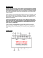
CONTROL SWITCHER
User’s Manual
(Preliminary)
www.voodoolab.com
Copyright ©2010 by Digital Music Corporation.
This publication is protected by copyright and all rights are reserved. Voodoo Lab,
Control Switcher, Pedal Power, Ground Control, and Commander are trademarks of
Digital Music Corp.
rev 0.8
INTRODUCTION
Voodoo Lab Control Switcher lets you replace your amp's footswitch to instantly
automate channel switching and much more. It easily interfaces with everything
from vintage combos to modern heads. Plus, each switch is completely isolated
so you can control multiple amps or other footswitchable devices from a single
Control Switcher.
Control Switcher is plug-and-play when used with Voodoo Lab controllers, such
as Ground Control Pro and Commander. It also works with any standard MIDI
foot controller, or MIDI capable multi-effects pedal like Line 6 PODxt Live or TC
Electronic Nova System.
Using Control Switcher with your amp gives you the ability to remotely control
each function and create preset combinations of amp channels, onboard boost,
reverb, EQ, and FX loops. Now everything can be automated along with your
other effects in a single stomp.
Control Switcher is also a great way to expand the capabilities an existing
Ground Control Pro and GCX Audio Switcher rig. Thanks to its compact, lowprofile design you can mount it inside your combo amp, head, pedalboard, or
rack.
CONNECTIONS
1. Power jack. Requires 9V AC or DC at 120mA.
2. MIDI IN. Receives MIDI commands and provides phantom power for Voodoo
Lab Ground Control Pro or Commander foot controllers.
3. MIDI OUT. Echoes commands from MIDI IN for chaining devices.
4. Control Jacks (4). Access to individual switch functions with 1/4” mono
jacks.
5. MULTI connector. Access to all 4 switch functions from a single connector.
6. Power LED. Indicates Control Switcher is powered on.
7. Buttons / Status LEDs. Buttons to toggle switch functions on/off. LEDs
indicate status. Also used to save programs and setup.
Switches
Control Switcher includes four automated switches which are used to replace
your amp’s footswitch. The switches can be accessed individually from the four
1/4” mono CONTROL jacks, or combined using the MULTI connector.
The MULTI connector provides access to all four switches with a common
ground. This is a standard 5-pin DIN connector which is commonly used for MIDI.
Plugging into any 1/4” jack isolates and removes that switch from the MULTI
connector.
MULTI Connector
Tip: If you want to make your own amp control cable using the MULTI connector,
start with a 5-pin active MIDI cable, cut off and replace the connector from one
end.
Please contact Voodoo Lab or refer to our web site for availability of special
cables for specific amps. If you don’t find the cable you need, please contact us
to request it.
MIDI Connections
Control Switcher receives MIDI commands from Ground Control Pro,
Commander, or other MIDI foot controller to turn individual switches on or off,
and recall preset combinations of switch settings.
You can generally route the MIDI signal from your foot controller to your devices
in any order that is convenient for cabling. Start by connecting a MIDI cable from
the MIDI OUT of your foot controller to the MIDI IN of your first device. Then
patch from its MIDI OUT (or MIDI THRU) to the MIDI IN of your next device.
Continue chaining in the manner until all devices have their MIDI inputs
connected.
Power
Normally, you will power Control Switcher from its supplied adapter. To use a
different adapter or power supply, you must provide 9VDC or 9VAC at 120mA to
a 5.5x2.5mm barrel connector.
Control Switcher can be powered by any output of a Voodoo Lab Pedal Power 2+
with the DIP switch in the normal position, or any 9V output of a Pedal Power
ISO-5, using the cable which is red on one end and black on the other. You can
also power it from any 9V output of a Pedal Power AC using the cable which is
red on both ends.
Control Switcher also provides phantom power to its MIDI IN jack which will
power the Voodoo Lab Ground Control Pro or Commander. You must use a MIDI
cable that has all 5-pins wired, commonly marked 5-pin active.
The supplied adapter has enough capacity to power both Control Switcher and
another foot controller as does Pedal Power AC. Pedal Power 2+ outputs 5 or 6,
and Pedal Power ISO-5 high current output will operate Control Switcher and
Commander only.
OPERATION
Once Control Switcher is connected to your amp and MIDI controller, you can
access individual switch functions by pressing the front panel buttons. The
corresponding LED will show the state of each switch. If your foot controller has
instant access buttons, these can also be assigned to directly control individual
switches.
You can save preset combinations of switch settings for recall with a single
button press. How to do this will depend on which type of MIDI foot controller
you’re using. The following sections explain using Commander with the different
types of controllers.
USE WITH GROUND CONTROL PRO
Using a Voodoo Lab Ground Control Pro MIDI foot controller, you will access
Control Switcher as if it were four loops of a GCX Guitar Audio Switcher. Ground
Control Pro assigns loops in the order the devices are chained. For example, a
Control Switcher connected directly to Ground Control Pro’s MIDI OUT will be
GCX#1 loops 1-4. A 2nd Control Switcher would then be GCX#1 loops 5-8.
Alternately, if MIDI is routed to a GCX first and then Control Switcher, the GCX is
#1 and Control Switcher becomes GCX#2.
You need to setup Ground Control Pro as if you have a GCX. Here’s how:
1.) Press both SETUP buttons to enter setup mode.
2.) Press EXPANDERS.
3.) Press YES/+ to turn on GCX-1. You have enabled GCX#1 loops 1-8. To
enable more GCX loops, press BANK ↓ then YES/+ to turn on GCX-2. You can
enable up to four GCX modules for 32 loops.
4.) Press either SETUP button to see “EXIT Y/N” then press YES/+ to exit setup
mode.
Please refer to the Ground Control Pro user’s manual for a detailed description of
how to assign instant access buttons to individual loops and create preset
combinations of loop settings.
USE WITH COMMANDER
Using a Voodoo Lab Commander, here’s how to create presets:
1.) Press Control Switcher buttons to select the switch functions you want.
2.) Select bank 1-5 or 6-10 on Commander.
3.) Hold down BANK/STORE until it starts blinking (about 3 seconds), then hit the
desired preset button at the same time.
Now recalling presets from Commander will configure your amp, and select any
desired combination of pedal effects.
Please refer to the Commander user’s manual for more detailed information.
USE WITH OTHER MIDI FOOT CONTROLLERS
You can use Control Switcher with any MIDI controller capable of sending
program change (PC) or control change (CC) messages. Following the
instructions below in the SETUP section of this manual, you will set Control
Switcher to respond to either PC, CC or both message types, as well as which
MIDI channel. If you are using CC, you also need to specify which group of CC
numbers.
Once setup, you can save and then recall preset combinations of switch settings
by sending a PC message from your MIDI foot controller. Here’s how:
1.) Send the PC message from your foot controller for the preset you want to
create.
2.) Set the Control Switcher switches to the desired combination.
3.) Press and hold button #1. At the same time, press button #4. The LEDs will
blink to confirm that you saved the preset.
Now whenever Control Switcher receives this PC message, it will recall your
switch settings.
Note: You must configure Control Switcher to respond to MIDI program change
messages. To do this, go to the following sections of this manual:
SETUP: MIDI Program Change and Control Change Enable
SETUP: Set MIDI Channel
To use MIDI control change messages for Instant Access buttons, go here as
well:
SETUP: Select Control Change Numbers
SETUP
Set Switch Function
Each of the four switches can be set to function as normal, reverse or
momentary.
Normal: This is the default setting and works correctly for most applications. The
LED shows the actual state of the switch. It will be off when the switch is off
(open), and on when the switch is on (closed). This is sometimes referred to as
“normally open” or N.O.
Reverse: This setting reverses the state of the LED. You should use reverse if
the LED is backwards. The LED will be on when the switch is off (open), and it
will be off when the switch is on (closed). This is sometimes referred to as
“normally closed” or N.C.
Momentary: Some amplifiers and effects will require the switch to be pulsed. This
simulates the action of a momentary switch. A momentary switch is on when you
step on it, and goes off immediately when you pick up your foot.
Here’s how you set the switch function:
1.) Apply power while holding down button #1. LED #1 will flash until you release
the button.
2.) Press each button to set the corresponding switch’s function. The LED
indicates the setting.
LED
Off
On
Blinking
Switch Function
Normal
Reverse
Momentary
3.) Remove power when finished.
Set Momentary Mode
Switches set to function as momentary will pulse once to turn on and pulse again
to turn off. This is how a momentary switch that selects between two amp
channels or controls a single function like boost or EQ will normally work. This is
the default and is called pulse on/off.
Some amps will use multiple momentary switches where each one selects a
different channel. For example, you may have three separate switches for clean,
rhythm and lead channels. In this case, you only pulse the switch for the channel
you are selecting. This is called pulse on only.
Here’s how to select between the two momentary modes:
1.) Apply power while holding down button #3. LED #3 will flash until you release
the button.
2.) Press button #3 to select the mode.
Momentary Mode
Pulse ON/OFF
Pulse ON only
LED #3
OFF
ON
3.) Remove power when finished.
Set MIDI Channel
MIDI program change and control change messages include a channel number,
1 through 16. Control Switcher will only respond to messages received on its
specified channel.
The default MIDI channel is 1.
Note: When Control Switcher is being controlled by a Voodoo Lab Commander
or Ground Control Pro, its MIDI channel is ignored.
Here’s how you set the MIDI channel:
1.) Apply power while holding down button #2. LED #2 will flash until you release
the button.
2.) Find your desired MIDI channel from the table and press each button to
match.
MIDI
Channel
1
2
3
4
5
6
7
8
9
10
11
12
13
14
15
16
LED #1
LED #2
LED #3
LED #4
OFF
ON
OFF
ON
OFF
ON
OFF
ON
OFF
ON
OFF
ON
OFF
ON
OFF
ON
OFF
OFF
ON
ON
OFF
OFF
ON
ON
OFF
OFF
ON
ON
OFF
OFF
ON
ON
OFF
OFF
OFF
OFF
ON
ON
ON
ON
OFF
OFF
OFF
OFF
ON
ON
ON
ON
OFF
OFF
OFF
OFF
OFF
OFF
OFF
OFF
ON
ON
ON
ON
ON
ON
ON
ON
3.) Remove power when finished.
MIDI Program Change and Control Change Enable
You can set whether Control Switcher responds to MIDI program change (PC),
control change (CC), both message types, or none.
Note: When using Voodoo Lab Ground Control Pro or Commander, you should
disable both PC and CC to take advantage of plug-and-play compatibility.
The default is both PC and CC disabled.
PC messages are used to recall preset conbinations of switch settings stored in
Control Switcher. This is commonly done with simple foot controllers that are not
capable of sending preset combinations of CC messages.
CC messages allow direct control of individual switches from your foot controller.
For example, this lets you use instant access buttons (IA) on your foot controller
to turn amp functions on and off.
Here’s how you set which MIDI messages Control Switcher will respond to:
1.) Apply power while holding down button #3. LED #3 will flash until you release
the button.
2.) Press buttons #1 and #2 according to this table.
Function
None (plug-and-play)*
PC only
CC only
Both PC & CC
LED #1
OFF
ON
OFF
ON
LED #2
OFF
OFF
ON
ON
*None is the correct setting for Voodoo Lab controllers only.
3.) Remove power when finished.
Select Control Change Numbers
Each MIDI control change (CC) message includes a controller number which
specifies the Control Switcher switch to turn on or off. You can select from eight
different groups of CC numbers.
The default group is CC numbers 80-83, which means that 80 controls switch #1,
81 controls switch #2, 82 controls switch #3, and 83 controls switch #4.
If you are using a Ground Control Pro, each group of CC numbers corresponds
to a set of four GCX loops. This allows you to force Control Switcher to respond
as if it were the specified GCX.
Here’s how you select which CC numbers Control Switcher will respond to:
1.) Apply power while holding down button #4. LED #4 will flash until you release
the button.
2.) Press buttons 1, 2 and 3 according to this table.
CC #
80-83
84-87
88-91
92-95
64-67
68-71
56-59
60-63
LED #1
OFF
OFF
OFF
OFF
ON
ON
ON
ON
LED #2
OFF
OFF
ON
ON
OFF
OFF
ON
ON
LED #3
OFF
ON
OFF
ON
OFF
ON
OFF
ON
GCX Loops
GCX#1 Loops 1-4
GCX#1 Loops 5-8
GCX#2 Loops 1-4
GCX#2 Loops 5-8
GCX#3 Loops 1-4
GCX#3 Loops 5-8
GCX#4 Loops 1-4
GCX#4 Loops 5-8
3.) Remove power when finished.
Factory Reset
You can restore all of the factory default settings and clear any saved presets by
the following steps:
1.) Apply power while holding down both buttons #2 and #3.
2.) LED #1 will be on. Press button #1.
3.) Press buttons #2, #3 and #4 as each LED comes on.
4.) LEDs will blink and then stay on. Remove power.
WARRANTY
Voodoo Lab warrants this product against any defects that are due to faulty
material or workmanship for a period of five years from the date of original retail
purchase. This warranty does not include damage to the product resulting from
accident or misuse.
If the product should become defective within the warranty period, Voodoo Lab
will repair it or replace it free of charge, provided it is returned freight prepaid to
Voodoo Lab with a valid RMA (return material authorization) number. Return
shipping will be paid by Voodoo Lab within the U.S. only.
This warranty shall not apply to any goods that have been repaired or altered by
anyone other than the manufacturer. There are no warranties which extend
beyond the terms described herein.
Should you experience any difficulty with this Voodoo Lab product, contact us as
described below. If it is determined that the product must be returned to the
factory for repair, you will be issued an RMA and given shipping and packaging
instructions.
HOW TO REACH US
You can reach us by any of the following:
Mail:
Voodoo Lab
3165 Coffey Lane, Santa Rosa, CA 95403
Tel:
707 545 0600
Fax:
707 545 9777
Email:
[email protected]
Forum:
www.voodoolab.com/forum