1
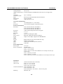
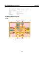
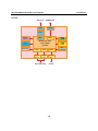
W315/325/345 Hardware User’s Manual www.moxa.com/product Second Edition, April 2008 © 2008 Moxa Inc., all rights reserved. Reproduction without permission is prohibited. W315/325/W345 Hardware User’s Manual The software described in this manual is furnished under a license agreement and may be used only in accordance with the terms of that agreement. Copyright Notice Copyright © 2008 Moxa Inc. All rights reserved. Reproduction without permission is prohibited. Trademarks MOXA is a registered trademark of Moxa Inc. All other trademarks or registered marks in this manual belong to their respective manufacturers. Disclaimer Information in this document is subject to change without notice and does not represent a commitment on the part of Moxa. Moxa provides this document “as is,” without warranty of any kind, either expressed or implied, including, but not limited to, its particular purpose. Moxa reserves the right to make improvements and/or changes to this manual, or to the products and/or the programs described in this manual, at any time. Information provided in this manual is intended to be accurate and reliable. However, Moxa assumes no responsibility for its use, or for any infringements on the rights of third parties that may result from its use. This product might include unintentional technical or typographical errors. Changes are periodically made to the information herein to correct such errors, and these changes are incorporated into new editions of the publication. Technical Support Contact Information www.moxa.com/support Moxa Americas: Toll-free: 1-888-669-2872 Tel: +1-714-528-6777 Fax: +1-714-528-6778 Moxa Europe: Tel: +49-89-3 70 03 99-0 Fax: +49-89-3 70 03 99-99 Moxa Asia-Pacific: Tel: +886-2-8919-1230 Fax: +886-2-8919-1231 Moxa China (Beijing office): Tel: +86-10-6872-3959/60/61 Fax: +86-10-6872-3958 Table of Contents Chapter 1 Introduction ..................................................................................................1-1 Overview.................................................................................................................................. 1-2 Package Checklist .................................................................................................................... 1-2 Product Features ...................................................................................................................... 1-3 Product Hardware Specifications............................................................................................. 1-3 Hardware Block Diagram ........................................................................................................ 1-5 W315 ............................................................................................................................ 1-5 W325 ............................................................................................................................ 1-6 W345 ............................................................................................................................ 1-7 Chapter 2 Hardware Introduction.................................................................................2-1 Appearance .............................................................................................................................. 2-2 W315 ............................................................................................................................ 2-2 W325 ............................................................................................................................ 2-2 W345 ............................................................................................................................ 2-3 Dimensions .............................................................................................................................. 2-4 W315 ............................................................................................................................ 2-4 W325 ............................................................................................................................ 2-5 W345 ............................................................................................................................ 2-6 LED Indicators......................................................................................................................... 2-7 Reset Button............................................................................................................................. 2-7 Real Time Clock ...................................................................................................................... 2-8 Chapter 3 Hardware Connection Description .............................................................3-1 Installing the W315/W325/W345 ............................................................................................ 3-2 Wiring Requirements ............................................................................................................... 3-3 Connecting the Power................................................................................................... 3-3 Grounding the Unit....................................................................................................... 3-3 Connecting Data Transmission Cables .................................................................................... 3-4 Connecting to the Network........................................................................................... 3-4 Connecting to a Serial Device ...................................................................................... 3-5 Connecting to the Serial Console Port.......................................................................... 3-5 Connecting an Antenna................................................................................................. 3-5 Installing a SIM Card and SD Card ......................................................................................... 3-6 Installing a SIM Card ................................................................................................... 3-6 Installing an SD Card for Storage Expansion ............................................................... 3-7 USB (W345 only) .................................................................................................................... 3-8 Relay Output (W345 only)....................................................................................................... 3-8 Appendix A FCC Warning Statement ................................................................................. 1 1 Chapter 1 Introduction The W315/W325/W345 series of wireless RISC-based embedded computers feature a GSM/GPRS module, RS-232/422/485 serial ports, and an Ethernet port in a small, rugged chassis. In addition, the W325 and W345 models come with an SD slot, and the W345 also has two USB 2.0 hosts and one relay output channel. The W300 series embedded computers are ideal for diverse, machine-to-machine embedded applications. The computers enable the wireless operation of traditionally wired network and serial devices, and can handle transparent data transfer, numeric computing, protocol conversion, data processing, and even data encryption. You will find it easier to build embedded systems for distributed peer-to-peer communication, turn wired devices into wireless devices, and introduce higher mobility and more intelligence to your system. In this chapter, we cover the various capabilities of the W300 series embedded computers. In this chapter, we cover the following topics: Overview Package Checklist Product Features Product Hardware Specifications Hardware Block Diagram ¾ W315 ¾ W325 ¾ W345 W315/325/W345 Hardware User’s Manual Introduction Overview The W315/W325/W345 wireless embedded computers are designed around the Moxa ART ARM9 32-bit RISC processor. Unlike the X86 CPU, which uses a CISC design, the Moxa ART ARM9 uses RISC architecture and modern semiconductor technology to provide a powerful computing engine without generating a significant amount of heat. The processor also integrates UART and LAN functions to provide exceptional communication performance, but without the bus bandwidth limitations associated with general ARM-based communication products. An onboard NOR Flash ROM and SDRAM provide ample storage capacity, and the SD slot gives applications extra room to expand. The built-in GSM/GPRS function supports the 850/900/1800/1900 MHz frequency bands, providing coding scheme from CS-1 to CS-4. The backup LAN port not only provides an alternative solution for networking, but also supports Ethernet clients, allowing any network device to plug in and connect to the GPRS network. The built-in RS-232/422/485 serial ports support a wide range of serial devices, making this platform suitable for data acquisition and protocol conversion applications. The Linux-based operating system comes pre-installed and ready to run, providing an open platform for software development. Software written for desktop PCs can be ported easily to W300 series embedded computers by using a common complier, so you do not need to spend a lot of time modifying existing software code. In addition, the operating system, device drivers, and user-developed software can all be stored in the built-in flash memory. Package Checklist The W300 Series includes the following models: W315-LX Mini RISC-based, ready-to-run, wireless embedded computer with GSM/GPRS, one serial port, LAN, SD, and Linux OS W325-LX Mini RISC-based, ready-to-run, wireless embedded computer with GSM/GPRS, two serial ports, LAN, SD, and Linux OS W345-LX RISC-based, ready-to-run, wireless embedded computer with GSM/GPRS, four serial ports, LAN, SD, USB, relay output, and Linux OS Each model is shipped with the following items: y y y y y y y y W300 Series wireless embedded computer Quick Installation Guide Document & Software CD 100 cm RJ45-to-RJ45 Ethernet cross-over cable CBL-4PINDB9F-100: 100 cm 4-pin header to female DB9 console port cable 1 dBi antenna Universal power adaptor Product Warranty Statement Optional Accessories y 35 mm DIN-rail mounting kit (DK-35A) NOTE: Please notify your sales representative if any of the above items are missing or damaged. 1-2 W315/325/W345 Hardware User’s Manual Introduction Product Features W315/W325/W345 series embedded comptuers have the following features: y y y y y y y y y y y y y y y Moxa ART 32-bit ARM9 RISC industrial communication processor 32 MB on-board RAM (64 MB for W345) 16 MB built-in flash memory RS-232/422/485 serial ports with software selectable interface Baudrate between 50 and 921.6Kbps; supports ANY BAUDRATE 10/100M Ethernet for backup networking Built-in quad band 850/900/1800/1900 MHz GSM/GPRS module GPRS class 10 Coding scheme from CS1 to CS4 SD card slot for storage expansion Designed to withstand continuous 5G vibration and a 50G shock LED indicators for status, serial transmission, and wireless signal strength Ready-to-run Linux platform Install on a DIN-rail or wall Fanless design for increased ruggedness Product Hardware Specifications System CPU RAM Flash Storage Expansion USB Relay Output Console port Button Other OS Moxa ARM9-based 32-bit RISC CPU, 192 MHz W315: 32 MB W325: 32 MB W345: 64 MB W315: 16 MB W325: 16 MB W345: 16 MB W315: SD slot x 1 W325: SD slot x 1 W345: SD slot x 1 W345:USB2.0 host x 2 Form C, SPDT x 1 Normal switching capacity: 2A@30 VDC Switching power: 60 W max. Switching voltage: 220 VDC max. Switching current: 2 A max. Operation time: 4 ms @ 20°C Initial contact resistance: 100 MΩ max. RS-232 x 1 (TxD, RxD, GND); 4-pin header output, “115200, n, 8, 1” Reset button x 1; supports “Reset to Factory Default” RTC, buzzer, Watchdog Timer Built-in Embedded Linux with MMU support; based on Linux Kemel 2.6 Cellular Communication Standard Compliance GSM (Global Service for Mobile) and GPRS (General Packet Radio Service) Radio Band Selection Quad-band 850 MHz, 900 MHz, 1800 MHz, and 1900 MHz GPRS Multi-slot Class Class 10 1-3 W315/325/W345 Hardware User’s Manual Coding Schemes GPRS Terminal Device Class CSD Data Transmission Rate SMS SIM Control Antenna Introduction CS1 to CS4 Class B (simultaneous GPRS/CSD connections are not supported) Up to 14,400 bps Point-to-point Text(MT/MO) and Cell Broadcast 3V/1.8V Interface 1 dBi antenna, 8.33 cm Network Communication LAN 10/100 Mbps RJ45 x 1, auto-sensing Protection 1.5 KV built-in magnetic isolation protection Serial Communication Serial Port W315: RS-232/422/485, male DB9 x 1 W325: RS-232/422/485, male DB9 x 2 W345: RS-232/422/485, male DB9 x 4 Protection 15 KV built-in ESD protection for all signals Data bits 5, 6, 7, 8 Stop bit(s) 1, 1.5, 2 Parity None, Even, Odd, Space, Mark Flow Control RTS/CTS, XON/XOFF, RS-485 ADDC™ Speed 50 bps to 921.6 Kbps; supports ANY BAUDRATE LEDs System GPRS LAN Serial Ready, SD activity (for W325 and W345 only) Enable, signal strength 10 M/Link, 100 M/Link (RJ45 connector) TxD, RxD Power Requirements Power Input 12 to 48 V Power Consumption In GPRS mode: W315: 1A @ 12 VDC W325: 1A @ 12 VDC W345: 1.2A @ 12 VDC with USB devices on each port at max spec In idle mode: W315: 240 mA @ 12 VDC W325: 270 mA @ 12 VDC W345: 800 mA @ 12 VDC with USB devices on each port at max spec Mechanical Dimensions (W x D x H) Construction Material Mounting (without wall mount ears or antenna) W315: 77 x 111 x 26 mm W325: 77 x 111 x 26 mm W345: 150 x 100 x 38 mm W315: aluminum, 1 mm W325: aluminum, 1 mm W345: aluminum, 1 mm / SECC, 1 mm for rear panel DIN-Rail, wall 1-4 W315/325/W345 Hardware User’s Manual Introduction Environment Operating Temperature -10 to 60°C (14 to 140°F), 5 to 95% RH Storage Temperature -20 to 80°C (-4 to 176°F), 5 to 95% RH Regulatory Approvals EMC Safety Other Warranty FCC, CE (Class A) UL, cUL RoHS, CRoHS, WEEE 5 years Hardware Block Diagram W315 Ethernet GSM/GPRS LAN Cellular PHY Power Circuit RTC Watchdog MAC UART MOXA ART CPU 32-bit ARM9 192 MHz UART UART Serial Port Console Port RS-232/422/485 RS-232 1-5 32MB RAM 16MB Flash SD Function W315/325/W345 Hardware User’s Manual Introduction W325 Ethernet GSM/GPRS LAN Cellular PHY Power Circuit MAC MOXA ART CPU 32-bit ARM9 192 MHz RTC Watchdog UART UART UART UART Serial Port 1 Serial Port 2 Console Port RS-232/422/485 RS-232 1-6 32MB RAM 16MB Flash SD Function W315/325/W345 Hardware User’s Manual Introduction W345 GSM/GPRS Ethernet USB 2.0 Host x 2 Cellular LAN Relay Output PHY MAC UART Power Circuit 64MB RAM MOXA ART CPU 32-bit ARM9 192 MHz RTC 16MB Flash SD Function Watchdog UART UART UART UART UART Serial Port 1 Serial Port 2 Serial Port 3 Serial Console Port 4 Port RS-232 RS-232/422/485 1-7 2 Chapter 2 Hardware Introduction The W300 series embedded computers are compact, well-designed, and built rugged enough for industrial applications. LED indicators help you monitor performance and identify trouble spots, multiple serial ports allow you to connect different devices for wireless operation, and the reliable and stable hardware platform lets you devote your attention to developing your applications. In this chapter, we cover the following topics: Appearance ¾ W315 ¾ W325 ¾ W345 Dimensions ¾ W315 ¾ W325 ¾ W345 LED Indicators Reset Button Real Time Clock W315/325/W345 Hardware User’s Manual Hardware Introduction Appearance W315 Wireless GSM/GPRS antenna Ethernet (10/100BaseTx) 12 to 48 VDC Serial console port 5 Internal SIM Card Slot (remove cover to access) Serial Port (RS-232/422/485) W325 Wireless GSM/GPRS antenna Ethernet (10/100BaseTx) 12 to 48 VDC Serial console port 5 1. Internal SD Slot for Storage Expansion 2. Internal SIM Card Slot (remove cover to access) Serial Port 1 (RS-232/422/485) Serial Port 2 (RS-232/422/485) 2-2 W315/325/W345 Hardware User’s Manual Hardware Introduction W345 Top View USB 2.0 Host Relay Output 1. Internal SD Slot for Storage Expansion 2. Internal SIM Card Slot (remove cover to access) USB LAN Reset Button RELAY Reset NO COM NC 12-48V 12 to 48 VDC Ethernet 10/100BaseTX Wireless GSM/GPRS antenna connector Front View USB 2.0 Host x 2 Wireless GSM/GPRS antenna Ethernet (10/100BaseTx) Relay Output 12 to 48 VDC 1. Internal SD Slot for Storage Expansion 2. Internal SIM Card Slot (remove cover to access) 5 Serial console port Serial Port 1 to 4 (RS-232/422/485) Bottom View Serial Port x 4 (RS-232/422/485) 2-3 W315/325/W345 Hardware User’s Manual Hardware Introduction Dimensions 26 mm (1.02 in) 77 mm (3.03 in) 88 mm (3.46 in) 100 mm (3.94 in) 2-4 148.1 mm (5.83 in) 25 mm (0.98 in) 315 43 mm (1.69 in) 111 mm (4.37 in) W315 W315/325/W345 Hardware User’s Manual Hardware Introduction 26 mm (1.02 in) 77 mm (3.03 in) 88 mm (3.46 in) 100 mm (3.94 in) 2-5 148.1 mm (5.83 in) 25 mm (0.98 in) 325 43 mm (1.69 in) 111 mm (4.37 in) W325 W315/325/W345 Hardware User’s Manual Hardware Introduction W345 USB RELAY LAN Reset NO COM NC 40.5 mm (1.59 in) 150 mm (5.91 in) 161 mm (6.34 in) 173 mm (6.81 in) 2-6 137.1 mm (5.40 in) 25 mm (0.98 in) 100 mm (3.93 in) 38 mm (1.50 in) 35 mm (1.38 in) 12-48V W345 W315/325/W345 Hardware User’s Manual Hardware Introduction LED Indicators Note that the W315 does not have an SD slot, so it does not have an SD LED. LED Name Ready SD GPRS LED Color Green Off Green Off LED Function Power is on and functioning normally Power is off or a power error exists SD card is detected SD card is not detected ON: GPRS is ready Blinking: Conflict with GPRS IP or no response from DHCP server GPRS is not ready or function error exists Number of glowing LEDs indicates signal strength 5: Excellent 4: Very good 3: Good 2: Fair 1: Bad No signal or GPRS connection failed 10 Mbps Ethernet link Green Off Signal Strength LAN TxD P1-P4 RxD P1-P4 Green Off Orange Green Off Green Off 100 Mbps Ethernet link Disconnected or short circuit Serial ports P1-P4 transmitting data Serial ports P1-P4 not transmitting data Serial ports P1-P4 receiving data Yellow Serial ports P1-P4 not receiving data Off Reset Button Hold in the reset button for 5 seconds to load the factory default configuration. After loading the factory defaults, the system will reboot automatically. We recommend that you use this function only if the software is not working properly. To reset the Linux system software, always use the software reboot command (“reboot”) to protect the integrity of your data. The reset button is NOT designed as a hard reboot for the embedded computer. ATTENTION Restoring default settings preserves your data Resetting the embedded computer to factory defaults will NOT format the user directory and will NOT erase the user’s data. The reset button only loads a configuration file. All files in the /etc directory will revert to their factory defaults, but all other user data will remain intact in the Flash ROM. Please note that if there is a problem with the /etc directory, the embedded computer may be unable to restore the factory default settings. 2-7 W315/325/W345 Hardware User’s Manual Hardware Introduction Real Time Clock The embedded computer’s real-time clock is powered by a lithium battery. We strongly recommend that you NOT replace the lithium battery on your own. If the battery needs to be changed, please contact the Moxa RMA service team. ATTENTION There is a risk of explosion if the wrong type of battery is used. To avoid this potential danger, always be sure to use the correct type of battery. Contact the Moxa RMA service team if you need to replace your battery. Caution There is a risk of explosion if the battery is replaced by an incorrect type. Dispose of used batteries according to the instructions on the battery. 2-8 3 Chapter 3 Hardware Connection Description The W300 series wireless embedded computers support multiple types of connections. GSM/GPRS, Ethernet, and one or more serial ports are built into every model. In addition, the computers come with a serial console port for monitoring bootup messages. All models include an SD storage expansion, USB ports for additional device and storage options, and relay output connections. With the open-source Linux kernel, you are free to develop custom applications for remote, wireless operation of your device. In this chapter, learn how to connect the embedded computer to the network and to various devices. In this chapter, we cover the following topics: Installing the W315/W325/W345 Wiring Requirements ¾ Connecting the Power ¾ Grounding the Unit Connecting Data Transmission Cables ¾ Connecting to the Network ¾ Connecting to a Serial Device ¾ Connecting to the Serial Console Port ¾ Connecting an Antenna Installing a SIM Card and SD Card ¾ Installing a SIM Card ¾ Installing an SD Card for Storage Expansion USB (W345 only) Relay Output (W345 only) W315/325/W345 Hardware User’s Manual Hardware Connection Description Installing the W315/W325/W345 Wall or Cabinet Mounting The W315/325/345 embedded computers have built-in “ears” for attaching the embedded computers to a wall or the inside of a cabinet. We suggest using two screws per ear to attach the W315/325/345 to a wall or cabinet. The heads of the screws should be less than 6.0 mm in diameter, and the shafts should be less than 3.5 mm in diameter, as shown by the figure at the right. 6.0 mm 3.5 mm 5 W315 GPRS GPRS DIN-Rail Mounting DIN-rail attachments can be purchased separately to attach the product to a DIN-rail. When snapping the attachments to the DIN-rail, make sure that the stiff metal springs are at the top. 3-2 W315/325/W345 Hardware User’s Manual Hardware Connection Description Wiring Requirements This section describes how to connect serial devices to the embedded computer. You should read and follow these common safety precautions before proceeding with the installation of any electronic device: y Use separate paths to route wiring for power and devices. If power wiring and device wiring paths must cross, make sure the wires are perpendicular at the intersection point. NOTE: Do not run signal or communication wiring together with power wiring in the same wire conduit. To avoid interference, wires with different signal characteristics should be routed separately. y Use the type of signal transmitted through a wire to determine which wires should be kept separate. The rule of thumb is that wiring that shares similar electrical characteristics can be bundled together. y Keep input wiring and output wiring separate. y It is advisable to label the wiring to all devices in the system. ATTENTION Safety First! Be sure to disconnect the power cord before installing and/or wiring your W315/325. Wiring Caution! Calculate the maximum possible current in each power wire and common wire. Observe all electrical codes dictating the maximum current allowable for each wire size. If the current goes above the maximum ratings, the wiring could overheat, causing serious damage to your equipment. Temperature Caution! Be careful when handling the unit. When the unit is plugged in, the internal components generate heat, and consequently the outer casing may feel hot to the touch. Connecting the Power The PC’s power source should be provided by a UL listed class 2 or “Limited Power Source” (LPS), with external adaptor output rated 12 to 48 VDC, minimum 1.2A. If the power is supplied properly, the “Ready” LED will glow a solid green after a 25 to 30 second delay. Grounding the Unit Grounding and wire routing help limit the effects of noise due to electromagnetic interference (EMI). Before connecting any devices, run a ground wire from the ground screw to the grounding surface. 3-3 W315/325/W345 Hardware User’s Manual Hardware Connection Description ATTENTION This product should be mounted to a well-grounded mounting surface such as a metal panel. SG SG: The Shielded Ground (sometimes called Protected Ground) contact is the left most contact of the 3-pin power terminal block connector when viewed from the angle shown here. Connect the SG wire to an appropriate grounded metal surface. V- V+ 12-48V Connecting Data Transmission Cables This section describes how to connect the W315/325/345 embedded computers to the network, serial devices, and a serial COM terminal. Connecting to the Network Plug your network cable into the embedded computer’s Ethernet port. The other end of the cable should be plugged into your Ethernet network. When the cable is properly connected, the LEDs on the embedded computer’s Ethernet port will glow to indicate a valid connection. The 10/100 Mbps Ethernet LAN port uses 8-pin RJ45 connectors. The following diagram shows the pinouts for these ports. 8 1 8 1 The LED indicator in the lower right corner glows a solid green color when the cable is properly connected to a 100 Mbps Ethernet network. The LED will flash on and off when Ethernet packets are being transmitted or received. The LED indicator in the lower left corner glows a solid orange color when the cable is properly connected to a 10 Mbps Ethernet network. The LED will flash on and off when Ethernet packets are being transmitted or received. 3-4 Pin 1 2 3 4 5 6 7 8 Signal ETx+ ETxERx+ ----ERx----- W315/325/W345 Hardware User’s Manual Hardware Connection Description Connecting to a Serial Device Use a serial cable to plug your serial device into the embedded computer’s serial port. Serial ports P1 to P4 have male DB9 connectors and can be configured for RS-232, RS-422, or RS-485 communication by software. The pin assignments are shown in the following table: DB9 Male Port 1 2 3 4 5 6 7 8 9 RS-232/422/485 Pinouts Pin RS-232 RS-422 1 2 3 4 5 6 7 8 DCD RxD TxD DTR GND DSR RTS CTS TxDA(-) TxDB(+) RxDB(+) RxDA(-) GND ------- RS-485 (4-wire) TxDA(-) TxDB(+) RxDB(+) RxDA(-) GND ------- RS-485 (2-wire) ----DataB(+) DataA(-) GND ------- Connecting to the Serial Console Port The serial console port is a 4-pin pin-header RS-232 port. It is designed for serial console terminals, which are useful for viewing boot up message. Serial Console Port & Pinouts 4 3 2 1 Serial Console Cable Pin Signal 1 TxD 2 RxD 3 NC 4 GND Connecting an Antenna The W315/325/345 embedded computers come with a 1 dBi antenna for GPRS communication. Connect the antenna to the SMA connector located on the front panel of the embedded computer. Connect the antenna to the computer by rotating it in a clockwise direction. Antenna Connector GSM/GPRS Antenna 3-5 W315/325/W345 Hardware User’s Manual Hardware Connection Description Installing a SIM Card and SD Card Installing a SIM Card The W315/325/345 embedded computers have a built-in GSM/GPRS cellular module to provide long-range communication. SIM (Subscriber Identity Module) cards are used to authenticate and identify subscribers when connecting to a network. The SIM card and SD card slot are located on the right side of the W315/325’s casing, and on the front panel of the W345. W345 W315/W325 SIM Card/SD Card Slot SIM Card/SD Card Slot Follow these steps to install a SIM card: Step1: Before you install a SIM card, make sure the embedded computer is powered off. Step2: Use a screwdriver to remove the protective cover to access the slot. Note that the SD slot and SIM card slot for the W315/W325 share the same protective cover. W345 W315/W325 Step3: When inserting the SIM card, make sure the chip is facing upwards. Plug the SIM card directly into the slot. 3-6 W315/325/W345 Hardware User’s Manual Hardware Connection Description W315/325 SIM Card Slot SD Card Slot W345 SD Card Slot SIM Card Slot Step 4: Power on the embedded computer and tart the operating system. Step 5: To operate GPRS connection, please refer to the operating system user’s manual for further detail. NOTE: To remove the SIM card from the slot, press the SIM card in slightly with your finger, and then remove your finger to allow the card to spring out partially. You may now grasp the top of the card with two fingers and pull it out. Installing an SD Card for Storage Expansion The W315/W325/W345 provide an SD slot for storage expansion. The SD slot allows users to plug in a Secure Digital (SD) memory card compliant with SD standard V1.0 for up to 1 GB of additional memory space. The following steps show you how to install SD card. W315/W325 The SD slot is located on the right side of the W315/W325 casing. To install an SD card, first remove the protective cover to access the slot, and then plug the SD card directly into the slot. Step 1: Use a screwdriver to remove the screws holding the SD/SIM card slot’s outer cover. Step 2: After removing the cover, insert the SD memory card into the slot. 3-7 W315/325/W345 Hardware User’s Manual Hardware Connection Description SIM Card Slot SD Card Slot W345 The SD slot is located on the front panel of the W345. To install an SD card, you must first remove the protective cover to access the slot, and then plug the SD card directly into the slot. Step 1: Use a screwdriver to remove the screws holding the SD/SIM card slot’s outer cover. Step 2: After removing the cover, insert the SD memory card into the slot. SD Card Slot SIM Card Slot NOTE: To remove the SD card from the slot, press the SD card in slightly with your finger, and then remove your finger to allow the card to spring out partially. You may now grasp the top of the card with two fingers and pull it out. USB (W345 only) The W345 includes two USB 2.0 hosts. The hosts can be used for an external flash disk or hard drive for storing large amounts of data. RELAY 3-8 NC COM The W345 includes a relay output channel. A 3-pin terminal block is used for the relay output connection. Pinouts as shown in the figure at the right. NO Relay Output (W345 only) A Appendix A FCC Warning Statement This device complies with Part 15 of the FCC Rules. Operation is subject to the following two conditions: 1. This device may not cause harmful interference. 2. This device must accept any interference received, including interference that may cause undesired operation. This equipment has been tested and found to comply with the limits for a class B digital device, pursuant to part 15 of the FCC Rules. These limits are designed to provide reasonable protection against harmful interference in a residential installation. This equipment generates, uses, and can radiate radio frequency energy, and if not installed and used in accordance with the instructions, may cause harmful interference to radio communications. However, there is no guarantee that interference will not occur in a particular installation. If this equipment does cause harmful interference to radio or television reception, which can be determined by turning the equipment off and on, the user is encouraged to try to correct the interference by one or more of the following measures: y R eorient or relocate the receiving antenna. y I ncrease the separation between the equipment and receiver. y C onnect the equipment to an outlet on a circuit different from that to which the receiver is connected. y Consult the dealer or an experienced radio/TV technician for help. CAUTION: Any changes or modifications not expressly approved by the party responsible for compliance could void the user’s authority to operate the equipment. Prohibition of co-location: This device and its antenna(s) must not be co-located or operating in conjunction with any other antenna or transmitter. Safety Information: To maintain compliance with the FCC’s RF exposure guidelines, when installing and/or operating this equipment, you should maintain a minimum distance of 20 cm between the transmitter and your body. Use only the supplied antenna. Unauthorized antennae, modifications, or attachments could damage the transmitter and may violate FCC regulations. The device includes a GPRS module. This module has approved by FCC. The FCC ID is 09EQ24PL001