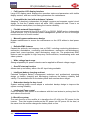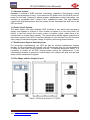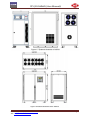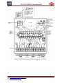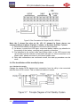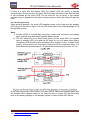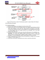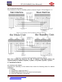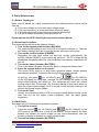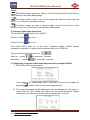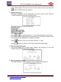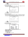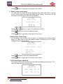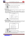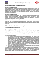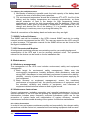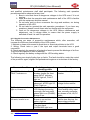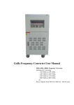
1
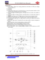
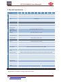
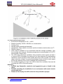
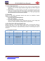
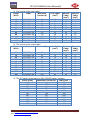
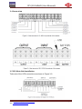
 PHD Powerhouse Distributions in Partnership with Allis Electric Co. 3 Phase UPS ST5 Series
(10~160KVA)
User Manual ST5 (10‐160kVA) User Manual
Note Please read the user’s manual carefully before operation, to understand the correct
operation of the UPS. Please keep the manual handy for future reference.
Warning!
The input and output of the UPS has dangerous high voltages which may
endanger the user’s safety. Please strictly follow the operating procedures,
and do not remove the cover of the UPS.
1. Please keep the UPS connected to ground before connecting the UPS.
2. The input & output voltages of the UPS are dangerous.
3. Please do not open the cover of the UPS by yourself because of danger of
electric shock.
4. Please turn off the mains input breaker and the battery breaker for any
emergency.
5. Please remove the cable between the battery & UPS before repairing. It’s
necessary to wait for another 5 minutes for discharging the capacitors,
because of the danger of electric shock.
6. The wires should be fastened to the terminals. It is prohibited to short the -ve
and +ve of the battery bank. It’s prohibited to touch any two of the wire
connectors or bare end of the connecting wires. Otherwise, it may lead to
damage of the battery bank or personal injury.
7. Please keep the battery bank away from fire and any instrument that may
cause sparks to prevent danger or damage.
8. Please do not open the battery, the overflow electrolyte is hazardous and may
cause injury.
9. Please contact professional personnel of the local dealer for any troubleshooting.
10. This is an A-grade product with electromagnetic compatibility.
11. This equipment must be installed and serviced by qualified personnel.
12. Before you replace the battery of a different brand and different type, make
sure the charging voltage is correct with the UPS charging voltage due to the
different required charging voltages of different battery types. If in any doubt,
please consult with the manufacturer. Any changes to the system
configuration, structure and composition will influence the performance of the
UPS, please consult with the manufacturer prior to doing any changes.
PHD: http://www.phdpowerhouse.co.za AEC: http://www.allis.com.tw Page 2 ST5 (10‐160kVA) User Manual
Table of Contents 1. System Overview ........................................................................................................................................................................ 4
1.1 Brief Introduction .................................................................................................................................................................. 4
1.2 Configuration ............................................................................................................................................................................. 4
1.2.1 Basic Configuration ........................................................................................................................................................... 4
1.2.2 Utility Mode .................................................................................................................................................................. 4
1.2.3 Battery Mode ................................................................................................................................................................ 5
1.2.4 Bypass Mode ............................................................................................................................................................... 5
1.2.5 Maintenance Bypass Mode .......................................................................................................................................... 6
1.3 System Features and Advantages ....................................................................................................................................... 6
1.4 Rectifier system.................................................................................................................................................................... 7
1.5 Inverter system .................................................................................................................................................................... 8
1.6 Static Switch System ........................................................................................................................................................... 8
1.7 Maintenance Bypass Switch System ................................................................................................................................... 8
1.8 The Shape and the Display Panel ....................................................................................................................................... 8
2. Physical Specification ............................................................................................................................................................... 17
3. Installation of UPS .................................................................................................................................................................... 18
3.1 Selection of location and environment ............................................................................................................................... 18
3.1.1 Location requirement ................................................................................................................................................. 18
3.1.2 Environment Requirement ......................................................................................................................................... 19
3.1.3 Power Supply Requirement ....................................................................................................................................... 20
3.2 Unpacking .......................................................................................................................................................................... 20
3.3 The Selection for UPS Input/Output Cable ........................................................................................................................ 20
3.4 Connection ......................................................................................................................................................................... 22
3.5 UPS Main Unit Installation ................................................................................................................................................. 22
3.6 The Installation of Hot standby System ............................................................................................................................. 23
3.6.1 The Basic Principle .................................................................................................................................................... 23
3.6.2 Work Engineering ...................................................................................................................................................... 24
3.6.3 Connection Procedure ............................................................................................................................................... 25
3.7 Installation Check ............................................................................................................................................................... 26
3.7.1 Checks on the Cabinet ............................................................................................................................................... 26
3.7.2 Check on Electrical Connections ............................................................................................................................... 27
3.8 Installation Steps of the Three-Phase Series (for example 10~60KVA)........................................................................... 27
4. Daily Maintenance .................................................................................................................................................................... 31
4.1 Before Turning on .............................................................................................................................................................. 31
4.2 Bootstrap Procedure .......................................................................................................................................................... 31
4.3 Shut Down ......................................................................................................................................................................... 31
4.4 Operation Procedure for the Maintenance Switch: ............................................................................................................ 32
5. The Operation Procedure of the LCD Display .......................................................................................................................... 32
5.1 the Buttons ......................................................................................................................................................................... 32
5.2 Startup/Shut-down Operation ............................................................................................................................................ 33
5.3 Displaying Contents and Related Operation (for example 80KVA) ................................................................................... 33
6. The Connection for Communication Port .................................................................................................................................. 38
6.1 RS232 Communication ...................................................................................................................................................... 38
6.2 RS485 Communication ...................................................................................................................................................... 38
6.3 Dry connection communication .......................................................................................................................................... 38
7. The selection and maintenance for options .............................................................................................................................. 38
7.1 The Application of Battery ....................................................................................................................................................... 38
7.1.1 Charging /Discharging for battery. ............................................................................................................................. 38
7.1.2 The Selection of Battery ............................................................................................................................................. 38
7.1.3 Battery Use and Maintenance .................................................................................................................................... 39
7.2 SNMP Card and Software .................................................................................................................................................. 39
7.3 UPS Concentrated Monitor ................................................................................................................................................ 39
8. Maintenance ............................................................................................................................................................................. 39
8.1 Machinery management .................................................................................................................................................... 39
8.2 Maintenance Instructions ................................................................................................................................................... 39
8.2.1 Safety Precautions ..................................................................................................................................................... 39
8.2.2 Regular Preventive Maintenance ............................................................................................................................... 40
9. Package, Transportation and storage ....................................................................................................................................... 42
9.1 Package ............................................................................................................................................................................. 42
9.2 Transportation .................................................................................................................................................................... 42
9.3 Storage.......................................................................................................................................................................... 42
PHD: http://www.phdpowerhouse.co.za AEC: http://www.allis.com.tw Page 3 ST5 (10‐160kVA) User Manual
1. System Overview 1.1 Brief Introduction This series is a true sine wave on-line UPS with high performance, adopting
advanced techniques to protect IT, communication devices, electrical machinery,
medical equipment etc. from disturbances or losing data from power failures. This
product can be used to resolve all kinds of power problems such as power
interruptions, voltage faults, electronic noise, peaks, instantaneous voltage dips,
lightning, instantaneous voltage fluctuations, frequency fluctuations etc.
1.2 Configuration 1.2.1 Basic Configuration This UPS includes: Input Breaker, Input Filter & Protection Circuit, Rectifier, Inverter,
Static Switch, Bypass Breaker, Isolation Transformer, Output Filter & Battery group
etc. as showed in Figure 1-1. When the utility is normal, AC power goes through the
filter and rectifier and then changes to DC power to the inverter for charging the
battery bank, which can supply clean power to the load at no transfer time.
This system includes four operation modes: utility mode, battery mode, bypass mode
and maintenance bypass mode, showed as follows:
1.2.2 Utility Mode As shown in Figure 1-2, at the status of the utility normal, the rectifier changes the
AC power to DC power to the inverter and charges the battery bank. Through the
process of AC power changing to DC power, the inverter can supply more reliable
and clean power to the load, as the rectifier can correct the problems associated with
voltages, noise, unstable frequency and so on.
PHD: http://www.phdpowerhouse.co.za AEC: http://www.allis.com.tw Page 4 ST5 (10‐160kVA) User Manual
1.2.3 Battery Mode As shown in Figure 1-3, when the utility is abnormal, the battery connected to the DC
BUS will supply power to the inverter, to protecting the load from AC power
interruptions.
1.2.4 Bypass Mode As shown in Figure 1-4, when the inverter has failed (due to any conditions such as
over-temperature, short circuit, output voltage abnormal, overload and so on), the
inverter should shut off automatically. If the utility is normal when the inverter fails,
the switch will switch to bypass power to supply power to the load.
PHD: http://www.phdpowerhouse.co.za AEC: http://www.allis.com.tw Page 5 ST5 (10‐160kVA) User Manual
1.2.5 Maintenance Bypass Mode As shown in Figure 1-5, when you are maintaining or changing the battery bank, and
the power must not be interrupted, you can shut off the inverter, and turn on the
maintenance breaker, then turn off the rectifier and bypass breaker. In this mode, AC
power goes through the maintenance breaker to supply power to the load. And at
this time, there may be no power inside the UPS except on the output transformer,
and the maintenance personnel can work without any risk.
1.3 System Features and Advantages True double conversion on line UPS
Complete isolation at input/output by transformers, and adopting high efficiency
IGBT power modules for protection against lightning, voltages between neutral and
ground and all kinds of pulses and disturbances in the power network to supply a
safe operating environment for the equipment.
Digital DSP Control Technology
The inverter control, synchronous phase control, input rectifying control, logic control
etc. are all controlled by a DSP, as the control is with high precision, high speed, and
high system performance.
PHD: http://www.phdpowerhouse.co.za AEC: http://www.allis.com.tw Page 6 ST5 (10‐160kVA) User Manual
Full function LCD display interface
Large LCD display panel displays the operation status and parameters with visible
display content; and can record history parameters for maintenance.
Compatible the load with unbalance 3 phases
Adopting 3 absolutely independent full bridge inverters and separate control circuit
design, so that the 3 phase output will allow 100% unbalanced load. There is no
effect between each phase, increasing the inverter reliability.
Flexible network Supervisation
This series can supervise the UPS and PC’s by RS232, SNMP and an independent
remote monitor. It is a convenient power management system for one to one single
monitor and one to N multi-monitor.
Manual bypass maintenance design
Bypass maintenance to ensure the maintenance on the UPS without a load power
break.
Reliable EMC features
Passed the authority and company test on EMC, including conducting disturbance,
radioactive disturbance, conducting anti-disturbance, radioactive anti-disturbance,
power fault, mass impulsion, static discharging, surge etc. The predominant EMC
features can be applied to high frequency communication, broadcasting audio and
video systems.
Wide voltage input range
Strong adaptability for power networks can be applied to different voltage ranges.
Own DC start-up function
Allows start up on battery without the AC input being available.
Intelligent battery charging and test
Patented intelligent battery management technique and professional managing
design on battery charging and discharging improves the battery reliability and
validity. The automatic test on the battery bank also reaches above target.
Redundant design for key circuit
System working power source adopts a redundant backup design to improve the
system running reliability.
Intellectual Fans control
Fans can adjust their speed in accordance with the load status to prolong their life
and reduce noise levels.
1.4 Rectifier system The main function of the rectifier is to transform the AC utility into DC power for the
inverter. Then the inverter transforms the DC power into AC power for the load, at
the same time the rectifier charges the battery bank on line.
PHD: http://www.phdpowerhouse.co.za AEC: http://www.allis.com.tw Page 7 ST5 (10‐160kVA) User Manual
1.5 Inverter system Inverter: It consists of IGBT modules, inductance, capacitors, filter boards, control
circuitry and protection circuitry. It can transform DC power from the DC BUS into AC
power for the load. Adopting 3 phase inverter independent control technology, the
machine is compatible with 3 phase 100% unbalanced loads. The high capacity
module with high performance and low losses of heat decreases the fault rate of the
UPS’s inverter.
1.6 Static Switch System The static switch uses high reliability SCR modules. It can switch the load power
supply from bypass to inverter or from inverter to bypass in a very short time (no
break); It also can switch the inverter output to bypass output, when there is an
inverter fault or another fault, instantly. The system never allows bypass output but to
shut down bypass input SCR to prevent damage to user devices from the incorrect
utility supply at abnormal bypass voltage, frequency and wrong phase rotation.
1.7 Maintenance Bypass Switch System For convenient maintainance, the UPS set has an internal maintenance bypass
breaker. It will be switched off normally, but will be opened only for hot maintenance
to keep the user load running without a break. To maintain personnel safety, it is
necessary to switch off all UPS internal power during the maintenance. If the
maintenance breaker is opened at normal status, the inverter will stop and the load
power will be switched into bypass.
1.8 The Shape and the Display Panel PHD: http://www.phdpowerhouse.co.za AEC: http://www.allis.com.tw Page 8 ST5 (10‐160kVA) User Manual
PHD: http://www.phdpowerhouse.co.za AEC: http://www.allis.com.tw Page 9 ST5 (10‐160kVA) User Manual
PHD: http://www.phdpowerhouse.co.za AEC: http://www.allis.com.tw Page 10 ST5 (10‐160kVA) User Manual
PHD: http://www.phdpowerhouse.co.za AEC: http://www.allis.com.tw Page 11 ST5 (10‐160kVA) User Manual
PHD: http://www.phdpowerhouse.co.za AEC: http://www.allis.com.tw Page 12 ST5 (10‐160kVA) User Manual
PHD: http://www.phdpowerhouse.co.za AEC: http://www.allis.com.tw Page 13 ST5 (10‐160kVA) User Manual
PHD: http://www.phdpowerhouse.co.za AEC: http://www.allis.com.tw Page 14 ST5 (10‐160kVA) User Manual
Explanation :
1) LCD display: Show the running parameter and status of UPS (as voltage,
current, load etc.)
2) on button
3) off button
4) Phase alarm light (red): The light will be on when the phase rotation of the
rectifier input or bypass input is not clockwise.
5) Work flow light of rectifier (green): The light will be on when the rectifier is
normal.
6) Work flow light of inverter (green): The light will be on when the inverter is
normal.
7) Bypass alarm light (red): The light will be on when there is bypass output.
8) Battery low alarm light (red): The light will be on when the battery is low.
9) Overload alarm light (red): The light will be on when the output of the UPS is
overloaded.
10) Fault alarm light (red): The light will be on when rectifier, inverter or bypass is
faulty.
11) Scroll up button: Use to lookup display contents of LCD.
12) Enter button: Use to lookup display contents of LCD.
13) Backup button: Use to lookup display contents of LCD.
14) Scroll down button: Use to lookup display contents of LCD.
15) Scroll left button: Use to lookup display contents of LCD and turn on LCD
screen light.
PHD: http://www.phdpowerhouse.co.za AEC: http://www.allis.com.tw Page 15 ST5 (10‐160kVA) User Manual
A. LCD display: Displaying UPS operation status and parameters (i.e. voltage,
current, loading etc).
B. Utility input indicator (Green): Being on at normal utility.
C. Rectifier indicator (Green): Being on at rectifier normal status.
D. Scroll-up: For looking over LCD displaying contents.
E. Scroll-left: For looking over LCD displaying contents.
F. Scroll-down: For looking over LCD displaying contents.
G. On Button: For starting up the UPS with H button.
H. Enter: For starting up the UPS with G button, and shutting down with I button.
I. Off Button: For shutting down the UPS with H button.
J. Enter: For looking over LCD displaying contents.
K. Turn back: For looking over LCD displaying contents.
L. Battery indicator (Green): Being on at battery supplying status.
M. Inverter indicator (Green): Being on at inverter normal status.
N. Output indicator (Green): Being on at output voltage normal status.
O. Bypass indicator (Green): Being on at bypass supply status.
P. Bypass maintenance indicator (Green): Being on at bypass maintaining
status.
Q. Fault alarm indicator (Red): Being on at rectifier, inverter, or bypass fault.
R. Over load alarm indicator (Red): Being on at UPS output over load.
S. Low battery alarm indicator (Red): Being on at low battery.
T. Bypass alarm indicator (Red): Being on at bypass output.
U. Phase alarm indicator (Red): Being on at wrong phase on rectifier input or
bypass input.
PHD: http://www.phdpowerhouse.co.za AEC: http://www.allis.com.tw Page 16 ST5 (10‐160kVA) User Manual
2. Physical Specification Model 10kVA 15kVA Input Topology 20kVA
30kVA
40kVA
50kVA
Voltage (VAC) 400 ± 25%
Frequency (Hz) 50/60 ± 5%
Phase 3Φ4W+GND
100kVA 120kVA
3Φ4W
Voltage(VAC) L‐N: 220/230/240, L‐L: 380/400/415 (user selectable) Frequency (Hz) 50/60 ± 0.2% (battery mode)
Unbalance three phase voltage stabilisation with full load ≤2%, compatible 100% unbalanced load Waveform Sine wave, THD < 3% at linear load
Switch Time (ms) 0
Efficiency ≥90%
Overload Capacity 125% for 15mins, 150% for 1min
Maintenance Switch Maintenance switch with no switching time Start‐up Provided with DC Start‐up function
LCD Display Input Voltage/Frequency, Output Voltage, Battery Voltage, Load, DC Current etc. LED Display Operation Status
Alarm Function Overload, AC input abnormal, Low Battery, Failure, SNMP RS232/485, dry connection communication signal Communication function
Battery Test Function As shown in section 5.3
Protection Function Battery low voltage, Overload, Over‐temperature, Output short circuit, Output over/low voltage
EMC GB/T 7260.3‐2003
Noise (dB) <65
Cooling Fans
Operating 0
Temperature ( C) 0‐40 Relative Humidity 0‐95%, No condensation
Dimensions (W x D x H) (mm) Weight (Kg) 160kVA
12Vx29 = 348V
Phase Output 80kVA Three Phase Input, 3 Phase Output, True Online Double Conversion Battery Voltage (VDC) Other 60kVA
500 x 800 x 1180 250 290 300
320
400
1200 x 800 x 1600 450
460
840
950 1180
1300
* Specifications are subject to change without prior notice. PHD: http://www.phdpowerhouse.co.za AEC: http://www.allis.com.tw Page 17 ST5 (10‐160kVA) User Manual
3. Installation of UPS One of the main functions of the UPS is to supply safe, pure and stable power to the
load, preventing the power source from disturbing fluctuations or power breaks.
Normally the life of the UPS is around 10 years (excludes the battery bank as the
validity for the battery bank is effected by various elements such as battery type,
usage, environment, humidity, installation etc.). It is very important to select a right
installation area and environment for extending the UPS’s life.
3.1 Selection of location and environment 3.1.1 Location requirement Location environment should meet the basic requirements for the equipment when
running normally.
1) Suitable and effective fire protection equipment should be arranged in the
UPS room.
2) UPS room can supply enough AC input voltage and power capacity for the
UPS to run normally. The utility supply to the UPS should be with a suitable
breaker.
3) Prohibit any flammable and explosive material from being stored in the UPS
room.
4) Finish the preparation of the UPS room and ground wires before installation.
The voltage between the neutral wire and ground wire (of the AC input
source) in UPS room should be under 5V.
5) The construction work for the UPS room should have finished before
installation.
6) The position for the UPS installation should be as close to the AC power
source as possible.
7) The floor must withstand the UPS’s weight and size as shown in Figure 3-1,
Figure 3-2 and Figure 3-3.
8) The UPS room should be locked and only appointed personnel can have the
key. The UPS room should only be accessible to the operator and
maintenance people.
PHD: http://www.phdpowerhouse.co.za AEC: http://www.allis.com.tw Page 18 ST5 (10‐160kVA) User Manual
3.1.2 Environment Requirement Environment temperature: 00C~+400C;
Relative humidity: 0%RH~95%RH, no condensation;
Cooling: Fan;
Altitude: Meet international standard;
Uprightness: There shall be no shock and the inclination shall not be over 50;
Pollution grade: II;
UPS must be installed in an environment that has enough ventilation, cool,
low humidity and clean air. Operating temperature recommended is 20~250C,
and humidity is about 50%.
• The UPS room should be ventilated, there should be some space (at least 1
m) around UPS to facilitate the opening of the front door and for maintenance
operations; there should be some space above the UPS (at least 1m) for the
upper extraction of heat. It is recommended that there should be some space
for the right and left of the UPS to facilitate UPS maintenance.
• Do not place anything on top of the UPS to block the ventilation fans and do
not place the UPS in hot environment.
Attention:
• Prohibit any flammable, explosive and aggressive gas or liquid in the
room.
• Prohibit operating the installation in an environment with metal electric
conducting dust.
• Please do not deploy the UPS under the fire protection sprayer.
•
•
•
•
•
•
•
PHD: http://www.phdpowerhouse.co.za AEC: http://www.allis.com.tw Page 19 ST5 (10‐160kVA) User Manual
3.1.3 Power Supply Requirement 1) This series UPS requires the utility input to be 3 phase 5 wires 398VAC.The
capacity of the AC utility supply should be larger than the UPS’s maximum
input power;
2) There should be a suitable breaker for the UPS in the distribution board in the
UPS room to isolate it from the utility supply. Input breaker, output breaker
and power db board cables are recommended in 3.3. The input neutral wire
can be connected to the UPS without a breaker.
3.2 Unpacking Remove all the UPS’s packaging material and select the installation location
carefully (as referred above).
1) Check the following fitting/options:
Keys, user’s manual
2) Check the specification of the UPS:
Check if the UPS’s capacity; input voltage and frequency, output voltage and
frequency, phase and battery voltage meet the requirements.
3.3 The Selection for UPS Input/Output Cable Different capacities of UPS need different grade cables. Unconformable cables or
breakers may lead to a fire risk. Please select the size of breakers and cables
connecting to the UPS input, output and battery as follows. The following are only for
reference:
1) The choice of breaker
Power (KVA)
Input
10
15
20
30
40
50
60
80
100
120
160
230/398V 3Φ
230/398V 3Φ
230/398V 3Φ
230/398V 3Φ
230/398V 3Φ
230/398V 3Φ
230/398V 3Φ
230/398V 3Φ
230/398V 3Φ
230/398V 3Φ
230/398V 3Φ
PHD: http://www.phdpowerhouse.co.za AEC: http://www.allis.com.tw Maximum Current
(A)
24
37
50
73
98
122
147
172
215
251
344
Breaker (A)
60
60
60
100
125
150
200
200
250
300
400
Page 20 ST5 (10‐160kVA) User Manual
2) The choice of the input cable
Power
Input
Maximum
(KVA)
Current (A)
10
15
20
30
40
50
60
80
100
120
160
230/398V 3Φ
230/398V 3Φ
230/398V 3Φ
230/398V 3Φ
230/398V 3Φ
230/398V 3Φ
230/398V 3Φ
230/398V 3Φ
230/398V 3Φ
230/398V 3Φ
230/398V 3Φ
24
37
50
73
98
122
147
172
215
251
344
3) The choice of the output cable
Power
Output
Current (A)
(KVA)
10
15
20
30
40
50
60
80
100
120
160
230/398V 3Φ
230/398V 3Φ
230/398V 3Φ
230/398V 3Φ
230/398V 3Φ
230/398V 3Φ
230/398V 3Φ
230/398V 3Φ
230/398V 3Φ
230/398V 3Φ
230/398V 3Φ
15
22
29
46
58
72
91
116
133
160
232
Line Cable
(mm2)
10
16
16
16
25
35
35
50
70
95
95
Line Cable
(mm2)
6
10
10
16
25
35
35
50
70
95
95
Neutral
Cable
(mm2)
10
16
16
16
25
35
50
70
95
95
95
Ground
Cable
(mm2)
6
6
6
6
10
10
16
16
25
25
25
Neutral
Cable
(mm2)
10
10
10
16
25
35
50
70
95
95
95
Ground
Cable
(mm2)
6
6
6
6
10
10
10
16
16
25
25
4) The DC cable (at the status of 300-410VDC battery voltage)
Power (KVA)
Maximum Current (A)
Cable (mm2)
24
60
10
37
60
15
50
60
20
73
100
30
98
125
40
122
150
50
147
200
60
172
200
80
215
250
100
251
300
120
344
400
160
PHD: http://www.phdpowerhouse.co.za AEC: http://www.allis.com.tw Page 21 ST5 (10‐160kVA) User Manual
3.4 Connection 3.5 UPS Main Unit Installation Take note of the UPS connections as shown in Figure 3-5:
PHD: http://www.phdpowerhouse.co.za AEC: http://www.allis.com.tw Page 22 ST5 (10‐160kVA) User Manual
Note: the 3 phase line wire as LA, LB, LC showed in figure above, are
corresponding to A phase, B phase, C phase, or R phase, S phase, T phase.
1) Remove the breaker cover board in the front of the machine.
2) As shown, connect the UPS input, output and battery cables; pay attention to
the polarity of the battery, avoiding wrong polarity connection.
3) Pay attention to the correct utility input phase order, or the UPS cannot start
up normally and the indicator on the panel will light on. If the connection is out
phase order, please reconnect in the correct phase order.
4) Only after connections are confirmed correct, the start-up procedure can be
done. 3.6 The Installation of Hot standby System 3.6.1 The Basic Principle Change the master UPS’s bypass input connection from the utility to be connected
with the slave UPS’s output. This is called hot backup in series.
PHD: http://www.phdpowerhouse.co.za AEC: http://www.allis.com.tw Page 23 ST5 (10‐160kVA) User Manual
If there is a fault with the master UPS, the master UPS will switch to bypass
automatically. At this moment, the slave UPS will take the output load, and the load
is still protected by the slave UPS. So the load will run as usual. If the master
machine stays in bypass and the slave machine stays in fault, the utility will take the
load.
3.6.2 Work Engineering While working properly, the main UPS supplies power to the load and the standby
UPS idly runs. As show in figure 3-8, the thick lines refer to the power passage of hot
the standby system
Note:
1) the two UPS’s in hot standby connection mode shall not share one battery
pack, instead, they shall have separate battery packs
2) The AC input(LA,LB,LC,N when three phase) of the main UPS, the bypass
input of standby UPS (L,N) and the AC input (LA,LB,LC,N when three phase)
of standby UPS should be from the same utility supply(LA,LB,LC,N when three
phase), at the same time, the phase rotation must be consistent. When it is
three phase the bypass input (L, N) should be connected to the utility (L2, N). In the case of the main UPS’s failure, the main UPS is switched to bypass status and
the standby UPS supplies power to the load. As show in figure 3-9, the thick lines
refer to the power passage of hot standby system in case of main UPS failure.
PHD: http://www.phdpowerhouse.co.za AEC: http://www.allis.com.tw Page 24 ST5 (10‐160kVA) User Manual
3.6.3 Connection Procedure 3.6.3.1 Connection Steps 1) Remove the breaker cover board in the front of the UPS.
2) Remove the short wire connecting between the bypass input breaker and the
utility input breaker of the main unit, and remove the neutral of the input.
Connect the 3-phase line wires of the standby unit to the bypass input breaker
in correct phase order; the output neutral of the standby unit to the input
neutral of the main unit.
3) Connect the utility input of the main unit to the utility input of the standby unit.
Attention: The utility input phase rotation should be correct, or the UPS
cannot start up normally and the phase rotation indicator on the LCD panel
will light on. The wrong phase rotation connections must be corrected.
4) Other connections are the same as the connections of a single unit, as shown
in figure 3-10 and figure 3-11.
5) Only after ensuring the connections are correct, can start-up be done.
PHD: http://www.phdpowerhouse.co.za AEC: http://www.allis.com.tw Page 25 ST5 (10‐160kVA) User Manual
3.6.3.2 Connection Procedure The connection of the hot standby system is shown in figure 3-10 and figure 3-11:
Note: the 3 phase line wires as LA, LB, LC shown in the figure above, are
corresponding to A phase, B phase, C phase, or R phase, S phase, T phase.
3.7 Installation Check 3.7.1 Checks on the Cabinet Complete the assembly on the cabinet then check the following items for cabinet
installation:
1) Steady;
2) Uprightness, angle less than 5°;
3) Cabinet panel should be on the same horizontal plane;
4) Check the tightness of all screws;
PHD: http://www.phdpowerhouse.co.za AEC: http://www.allis.com.tw Page 26 ST5 (10‐160kVA) User Manual
5) Check if any redundant material is left on the cabinet. If so, please remove
them.
6) Check for any scratches, damage or paint (that has been removed) on the
cabinet.
7) Check the cleanliness of the cabinet, clean any dust and dirt.
3.7.2 Check on Electrical Connections Please check the electrical connections as follows:
1) Input and power distribution examination: whether AC cables meet the
standard, any loose cables in the cabinet; 2) Check all connections, series no, line order, polarity for output and battery
connections. Recheck the battery connection polarity and order. 3) Make sure the installation is done according to specifications. 3.8 Installation Steps of the Three‐Phase Series (for example 10~60KVA)
Remove the UPS from its pallet for installation. The following is the installation
instruction of the Three-Phase Series (10~60KVA)
1) The external structure of the three-phase series (10~60KVA) is as follows
after unpacking:
2) Loosen the 4 carrying bolts M16×65 front and back of the main frame and
the 6 hex bolts M12×40 between the brackets and the mainframe, make
the wheels of the main frame make contact with the bracket. PHD: http://www.phdpowerhouse.co.za AEC: http://www.allis.com.tw Page 27 ST5 (10‐160kVA) User Manual
3) Loosen the brackets and the binding hex bolts M12×40 locked on the main
frame, then unlock the binding hex bolts M12×80 fixed to the pallet and
bracket, and remove the brackets.
4) The main frame is pushed from the bracket to the ground ramp.
PHD: http://www.phdpowerhouse.co.za AEC: http://www.allis.com.tw Page 28 ST5 (10‐160kVA) User Manual
5) Choose and layout the installation site, drive 4 expansion bolt M10 into the
ground. Required space: 506mm×525mm, the exposed height of the
expansion bolt should be within 50mm.
6) Mount “T” type brackets, cover gasketΦ10, spring gasketΦ10 and nut
M10, lock tight.
PHD: http://www.phdpowerhouse.co.za AEC: http://www.allis.com.tw Page 29 ST5 (10‐160kVA) User Manual
7) The main frame is pushed between the brackets, re-heighten the 4 loose
carrying bolts M16×65, lock tight between the main frame and brackets
with 6 hex bolts M12×40.
PHD: http://www.phdpowerhouse.co.za AEC: http://www.allis.com.tw Page 30 ST5 (10‐160kVA) User Manual
4. Daily Maintenance 4.1 Before Turning on Make sure all cables are rightly connected and the following items correct before
start-up.
1) If the input voltage is in the rated input voltage range.
2) If the input frequency is in the rated input frequency range.
3) If all loads connected to the output terminal are switched off.
4) If all the breakers and battery fuses are switch off.
Please operate the UPS following the procedure referred below.
4.2 Bootstrap Procedure The bootstrap should follow the steps as follows:
1) Turn on the bypass power breaker (BYPASS):
The power board begins to work, the LCD on the panel switches on. Then the
low battery indicator will light on and the buzzer will beep continuously.
2) Turn on the rectifier breaker (POWER):
Supposing the right input power will start the rectifier automatically, the
rectifier indicator (AC/DC) on the panel will switch on. The DC voltage will be
established completely after 20s, and the Battery low indicator and buzzer will
turn off.
3) Turn on the battery breaker (BATTERY):
Turn on the battery breaker, the rectifier starts to charge the battery bank.
4) Press the inverter button on the panel:
This series UPS’s start up or shut down operation adapts “double buttons
combination operation” to prevent the wrong buttons being pressed.
(for 10~60KVA) and
(for 80~160KVA)
At start-up, just press
on the LCD panel for more than 1 second, DC/AC indicator will switch on, the
invert output indicator will switch on. The equipment will come into normal
inverter output after 30 seconds. The first-time starting of this series does not
allow the output bypass supply, so it is normal for the first-time starting to be
without the bypass output voltage.
5) Turn on the load:
Usually one should wait till the UPS is running smoothly before turning on the
load, first turn on the higher power equipment, then the lower power
equipment.
4.3 Shut Down Shut down the UPS following the operation as below:
1) Turn off the inverter:
Press the buttons
(for 10~60KVA) and
(for 80~160KVA) on the
LCD panel at the same time to turn off the inverter. At this moment the static
breaker will transfer the power supply for the load automatically from the
inverter to bypass to prevent an output voltage break.
2) Turn off the battery breaker (BATTERY):
PHD: http://www.phdpowerhouse.co.za AEC: http://www.allis.com.tw Page 31 ST5 (10‐160kVA) User Manual
To turn off all UPS power, please continue to switch off the battery breaker, so
that the rectifier cannot get power from the DC BUS.
3) Turn off the rectifier input breaker (POWER):
Turn off the rectifier breaker, the rectifier can not supply DC power from the
AC utility to the DC BUS, the DC BUS will discharge the power slowly, it will
take the DC BUS about 2 minutes to complete this.
4) Turn off the bypass input breaker (BYPASS):
Before switching off the bypass input breaker, you have to ensure the output
load is off, or there will be no power output from the output terminal.
5) The shut down procedure will be finished after the LCD display and the LED
indicators switch off.
4.4 Operation Procedure for the Maintenance Switch: Press the buttons on the LCD panel
(for 10~60KVA) and
(for
80~160KVA) at the same time to turn off the inverter.
1) Turn off the rectifier breaker (POWER) and battery breaker (BATTERY) after
the bypass indicator on the panel lights on.
2) Position the maintenance switch/ maintenance breaker to the “BYPASS”/”ON”
position, turn off the bypass power breaker (BYPASS) after the bypass
maintenance indicator (BYPASS) on the panel switches on. Open the panel to
switch the main board SW1-3 shift switch to ON (or take out the connection
for the main control board CN14). After all the indicators on the panel switch
off, switch the main board SW1-3 shift switch to OFF (or resume the
connection for the main board CN14); then the UPS can be maintained.
3) After the maintenance is finished, turn on the bypass power breaker
(BYPASS). Switch the maintenance switch to the “UPS”/ “ON” position after
the bypass indicator on the panel (BYPASS) switches on; the bypass power
output for the UPS is initiating.
4) Then begin to do the operation as the 4th daily operating procedure.
5. The Operation Procedure of the LCD Display The LCD display can display all running statuses and parameters of the UPS. The
user can preset some UPS parameters and control the UPS by operating the
interface. The full LCD screen can display 5 lines of characters. More characters can
be displayed by turning up/down pages by scrolling. Elegant and simple operation
buttons facilitate the user operation.
5.1 the Buttons There are 5 buttons for this series whose function is as shown below:
This button means “upward scroll / parameter setting +” used for upward
scrolling when multi-lines of characters are displayed / adding parameter values
when setting parameters.
This button means “downward scroll / parameter setting—” used for downward
scrolling when multi-lines of characters are displayed / decreasing parameter values
when setting parameters.
PHD: http://www.phdpowerhouse.co.za AEC: http://www.allis.com.tw Page 32 ST5 (10‐160kVA) User Manual
This button means “parameter setting” used for selection switch when thera er
many options in the same display page.
This button means “enter” used for confirming the selected option with the
mark “>” or to confirm a parameter setting.
This button means “go back to previous page” used for turning back to the
previous menu or to return without parameters being inputted.
5.2 Startup/Shut‐down Operation This Series UPS On/Off keys for 10~60KVA:
Power on: Push
key for 1s
Power off: Push
key for 1s.
This series UPS’s start up or shut down operation adapts “double buttons
combination operation” to prevent the wrong operation for 80~160KVA.
They are positioned on the panel as:
Start-up ---- press
Shut down ---- press
for more than 1 second.
for more than 1 second.
5.3 Displaying Contents and Related Operation (for example 80KVA) 1) Shut off the UPS bypass breaker.
It will return to the normal page after 10 seconds. It also can be enabled by
pressing
button to return to the normal page directly.
2) The output parameter will be displayed in the normal page for this series. It
means that the LCD display will switch into the output parameter display
under power on without any buttons being pressed after 1 minute.
PHD: http://www.phdpowerhouse.co.za AEC: http://www.allis.com.tw Page 33 ST5 (10‐160kVA) User Manual
In this display page, the user can turn into fthe unction menu by pressing the
button. Other buttons are negative.
3) Single menu page:
This page is designed for the displaying of all menu options of the UPS, the
“>”mark indicates the presently selected option.
There are other menu options as follows:
BATTERY TEST
LANGUAGE
DATE&TIME SETTING
MANUFACTURER INFO
HISTORICAL EVENT
Press
to position the mark “>” at the selected option in the menu.
The mark at right up and right down means there are still some contents in the
screen that can be displayed by scrolling up or down.
Press
button to enter into the option with the “>” mark.
Press
button to go back to the normal output parameter page.
4) Rectifier parameter page:
This page displays the 3 phase input voltage, the frequency of the UPS
rectifier and the rectifier DC output voltage.
5) Bypass parameter page:
This page displays the UPS bypass 3 phase voltage and frequency.
PHD: http://www.phdpowerhouse.co.za AEC: http://www.allis.com.tw Page 34 ST5 (10‐160kVA) User Manual
Press
button to go back to the upper menu index
6) Output parameter page:
This page displays the UPS’s three phase output voltages and load
percentages for each phase.
Press
button to go back to the upper menu index.
7) Battery parameter page:
This page contains the UPS battery voltage and charging (discharging)
current. It will display the charging current when the UPS’s rectifier is normal;
it will display the discharging current when the UPS is running on the inverter.
Press
button to go back to the upper menu index.
8) Running status page:
This page contains all the UPS work statuses.
There are two other lines marked at bottom right of the screen.
OUTPUT:NORMAL
LOAD STATUS: NORMAL
TEMPERATURE: 260C
Press
buttons to scroll.
PHD: http://www.phdpowerhouse.co.za AEC: http://www.allis.com.tw Page 35 ST5 (10‐160kVA) User Manual
Press
button to go back to the upper menu index.
9) Buzzer mute control page:
The user can shut down the buzzer beeping alarm when the UPS is running
on the inverter when the mains has failed (power failure). The buzzer will set
the alarm automatically and this can be silenced.
Press
buttons to select the options for On/Off.
Press
button to confirm the selected status.
Press
button to go back to the upper menu index..
10) Battery test control page:
For the battery test function, the principle is to discharge the UPS’s battery
bank in a short time to test the battery validity by lowering the DC output
voltage while the input is still on.
Press
button to confirm the selected status.
Press
button to go back to the upper menu index.
11) UPS internal time adjusting:
This series UPS has an internal timer chip that can display present time. The
user can adjust the time on this page.
PHD: http://www.phdpowerhouse.co.za AEC: http://www.allis.com.tw Page 36 ST5 (10‐160kVA) User Manual
Press
button to move the mark to the position of year, month, date, hour,
minute, second.
Press
button to add or reduce the time parameter.
Press
button to confirm the adjusted time meter.
Press
button to go back to the upper menu index.
12) Manufacturer:
This page displays UPS manufacturer’s information, mode name, version and
equipment ID address No.
The ID address NO supply address coding information is used to
communication with the data port when supervising multiple machines via
RS485. It can be set with a series of codes in the UPS. It is recommended not
to change this setting.
Press
button to go back to the upper menu index.
13) History record page:
This page supplies some important history parameters, the time for the
parameters and related displays of the UPS. These are the basic reference
data for analysis on local networks during abnormal situations.
Press
Press
buttons to scroll up or down
button to go back to the upper menu index.
Press
+
buttons for more than 10 seconds to clean the history
record in the UPS memory to facilitate the fault analysis for maintenance. It is
recommended not to clean history data frequently.
PHD: http://www.phdpowerhouse.co.za AEC: http://www.allis.com.tw Page 37 ST5 (10‐160kVA) User Manual
6. The Connection for Communication Port 6.1 RS232 Communication There is a RS232 communication port on the panel display control board. As
standard there is also an SNMP card, supporting close communication for the UPS
enabling the remote control of UPS input voltage, frequency, and output voltage,
frequency, load settings etc and other parameters. Remotely switching the machine
on and off is also enabled.
6.2 RS485 Communication There is a RS485 communication port on the panel display control board, it can
support remote communication enabling the remote control on the UPS input
voltage, frequency, output voltage, frequency, loading etc parameters. Remotely
switching the machine on and off is also enabled.
6.3 Dry connection communication There are two dry connection communication ports on the panel display control
board. They are for low battery and utility fault; they are closed for low battery and
utility fault.
7. The selection and maintenance for options 7.1 The Application of Battery 7.1.1 Charging /Discharging for battery. The battery bank is an important apparatus to ensure the uninterrupted power supply
for the UPS. The battery bank connects with the battery branch circuit of the UPS
system. The power system will do float charging or balance charging on the battery
bank at power normal status; the battery supply will keep the user equipment on
when the power fails.
7.1.2 The Selection of Battery 1) The selection of the battery bank capacity depends on two factors. The
needed current for the load equipment in the power system and the battery
discharge time. Supposing the discharging current of the battery bank in the
power system is 80A, and the battery bank power supply time when the power
fails is 10h. So the system requires a battery capacity= battery discharging
current × the power supplying time at power failure =800Ah. That is the
practical capacity of the battery. Usually oversizing the batteries slightly to
allow for losses is standard practise as theory is often very different from
reality. The losses can be in the region of 20%.
2) Do not use different capacity batteries in series with each other. Do not use
different voltage batteries in parallel either.
Please do not connect different capacity battery banks in parallel mode (the different
battery’s internal resistance will affect the charging current procedure which will
result in different capacities of batteries not fully charging. That will result in two
different battery banks: one gets over charged, another one gets under charged.
PHD: http://www.phdpowerhouse.co.za AEC: http://www.allis.com.tw Page 38 ST5 (10‐160kVA) User Manual
7.1.3 Battery Use and Maintenance 1) Muti-banks of batteries in parallel mode, the total capacity of the battery bank
equals to the sum of all battery bank capacities.
2) The environment temperature should be in between 00C~400C, the life of the
battery and the battery temperature are inversely proportionate, so there
should extraction of heat in the design for high temperature battery
applications to prevent the high temperatures with the batteries. (When the
battery bank under goes an increase in temperature, the batteries will over
charge and shorten the life of the battery.) If it is possible, please fix air
conditioning in machinery room to prolong the battery life.
Check all connections of the battery bank and make sure they are tight.
7.2 SNMP Card and Software The SNMP card will be installed in the UPS’s internal SNMP card slot to enable
network remote management on the UPS. The user can supervise the UPS using IE
or other browsers. The operation manual for the SNMP device can be found on the
Net Agent installation disk.
7.3 UPS Concentrated Monitor A background monitoring software-concentrating monitor can enable background
supervisation of the UPS and it can be remotely switched on/off. The operation
manual for the device can be found on the its installation disk.
8. Maintenance 8.1 Machinery management The management of the UPS room includes environment, safety and equipment
management.
1) Basic target for environment safety management: Make sure the
environment’s temperature, humidity, brilliance, static disturbance, noise and
strong EMC disturbance to meet standard requirement to assure the stability,
reliability , security of power equipment. All for the normal power supplying for
load equipment.
2) Basic demand on equipment management: ensure the machinery
performance of equipment well, the electric performance of equipment meet
the standard, reliability and stability of equipment, and intactness of
equipment related technical reference and original record.
8.2 Maintenance Instructions Correct maintenance, including preventive and remedial maintenance, is key to
optimal operation of the UPS and will prolong the equipment’s life span. Preventive
maintenance includes some frequently executed procedures which are for the
prevention of system faults and maximization of system efficiency; remedial
maintenance includes trouble-shooting of the system for effective maintenance.
8.2.1 Safety Precautions In order to carry out system maintenance safely and successfully, the relevant safety
precautions must be carried out, essential tools and testing equipment shall be used
PHD: http://www.phdpowerhouse.co.za AEC: http://www.allis.com.tw Page 39 ST5 (10‐160kVA) User Manual
and qualified maintenance staff shall participate. The following safe operation
procedures shall be observed at any time:
1. Bear in mind that there is dangerous voltages in the UPS even if it is not
running.
2. Make sure that the operation and maintenance staff of the UPS is familiar
with the equipment and this manual.
3. Do not wear gold or silver ornaments like rings and watches, etc during
operation of the UPS.
4. Do not take for granted the safe operation procedures. If you have any
questions, please consult those who are familiar with the equipment.
5. Look out for dangerous voltages in the UPS. Before maintenance and
adjustment, use a voltage meter to ensure that the power supply is
switched off and it is safe for operation.
8.2.2 Regular Preventive Maintenance The following are steps of preventive maintenance which, after execution, will
increase the efficiency and reliability of the UPS system.
1. Maintain a clean environment to avoid dust or chemical pollution to the UPS.
2. Wiring; Check twice a year if the input and output terminals have a good
connection.
3. Check regularly the operation of extraction fans to prevent the blockage of air flow.
They must be replaced in case of damage.
4. Check regularly the battery voltage and the UPS working status.
The following are simple finding tips on faults. The fault should be under the control
of the product’s agent, eligible and professional engineer or technician of the factory.
Abnormal Condition
(1) AC/DC indicator off,
FAULT indicator on.
(2) Panel phase rotation
light on, buzzer on.
(3) Inverter output does
not work, buzzer is on.
Fault diagnosing and
checking points
Rectifier utility input
breaker closes, the front
panel INPUT indicator,
AC/DC light off, FAULT
light on.
The rectifier input voltage
abnormal, AC/DC light off,
FAULT light on.
Fault phase for AC input,
LCD displays the wrong
message, the front panel
phase light is on (PHASE).
Buzzer is on.
Rectifier does not start up.
Buzzer is on and low
battery light on.
Shows output over load.
The front panel
OVERLOAD light is on.
PHD: http://www.phdpowerhouse.co.za AEC: http://www.allis.com.tw Remedy
Open rectifier utility input
breaker.
Connect the normal
voltage for the rectifier.
Change the phase rotation
of the rectifier utility input
lines, normally exchange
two phases of LA, LB, LC
phase.
After the completion of the
rectifier slow start-up, the
buzzer alarm will stop.
Reduce UPS load.
Page 40 ST5 (10‐160kVA) User Manual
(4) UPS is of and
supplying 0VAC output at
utility fault.
(5) LCD or LED off
(6) Fan stops rotating
(7) Panel FAULT light on,
buzzer on
(8) Panel OVERLOAD
light on
(9) UPS can not switch to
inverter, bypass
supply is on.
(10) UPS can not switch
from bypass power
to inverter power.
(11) Abnormal
communication.
Battery breaker closed.
Switch on battery breaker.
All UPS breakers are
closed.
Power board fault
Abnormal LB phase output
voltage, fan fault
Short circuit at output
terminal (including load
short circuit).
Over temperature of
inverter heat sink.
The fuse on the inverter is
blown, or IGBT module
abnormal
Input power failure, battery
in low battery protection
for discharging.
UPS output overload.
Open one breaker on the
UPS front panel.
Call professional engineer.
Call professional engineer.
Make sure whether
bypass power input
voltage and frequency is
normal.
Fault on bypass/inverter
SCR driving board
Inverter fault.
Fault on bypass/inverter
SCR driving board.
Wrong connection of
communication cable
Communication Software
not installed successfully.
Wrong setting for PC
communication interface.
Excludes above problem,
still have no normal
communication.
Check bypass power
Voltage and frequency.
PHD: http://www.phdpowerhouse.co.za AEC: http://www.allis.com.tw Remove short circuit point,
shut down the UPS’s
inverter, restart inverter.
Reduce load, or balance
the loads;
Change fuse or IGBT
module
Restart at AC input
resume.
Reduce load.
Call professional engineer.
Call professional engineer.
Call professional engineer.
Reconnect with right port.
Install software correctly
Correct communication
port set.
Call professional engineer.
Page 41 ST5 (10‐160kVA) User Manual
9. Package, Transportation and storage 9.1 Package The main unit of the UPS is firstly packaged in a carton, and then in a wooden case
for more protection. There are some signs on the carton, such as model, volume,
date etc.
9.2 Transportation It should strictly conform to the care signs during transportation, and place the UPS
according to the care signs, to avoid the damage to the UPS. Do not leave the create
in the open because of rain or other elements which could damage the UPS.
9.3 Storage Place the equipment according to the care signs. Store the UPS in an environment
of 00C-400C and relative humidity of 20%-80%. The storage period in this condition is
for six months, over six months, the equipment should be checked, and the batteries
charged every three months.
PHD: http://www.phdpowerhouse.co.za AEC: http://www.allis.com.tw Page 42