1
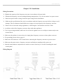
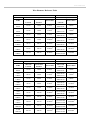
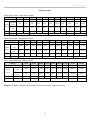
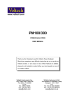
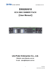
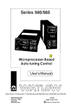
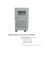
GoHz Frequency Converter User Manual 50Hz, 60Hz, 400Hz Frequency Converter Solutions for Converting - 110V 60Hz to 220V 50Hz, - 120V 60Hz to 240V 50Hz, - 230V 50Hz to 110V 60Hz, - 480V 60Hz to 400V 50Hz, etc… Power Capacity from 500 VA to 600 kVA - HZ-50 series www.GoHz.com Catalogue I. Safety Precautions ………………………………………………………………...…………………3 II. Working Principle ………………………………………………………………………….………4 III. Introduction ………………………………………………………………………..………………5 Product Features Applications Checklist Nameplate IV. Operation Panel and Functions ………………………………………………………...…………6 V. Operating Guide ……………………………………………………………………….……………7 Menu Selection Parameter Setting Procedure Specific Operation Settings VI. Placement…………………………………………………………………………...………………8 VII. Installation…………………………………………………………………..…………………9-12 Wiring Precautions Wiring Diagram Wire Diameter Reference Table Power Polarity Identification Methods Grounding System VIII. Specifications ……………………………………………………………………...……………13 Model Selection IX. Troubleshooting ……………………………………………………..……………………………15 X. Maintenance ………………………………………………………….……………………………16 www.GoHz.com Chapter I. Safety Precautions Read this user manual before using GoHz frequency converters. Keep this user manual near the frequency converter for reading at any time. Handle with care when transporting the frequency converter to avoid collision. Do not put the frequency converter on uneven or inclined place. Do not block the venting holes or slits to keep the frequency converter well-cooling effect, the back of the frequency converter should keep 10 cm (4 inches) away from the wall. Double check the frequency converter and power supply specifications are matching and well-wired before power connection to avoid any careless damaged. Frequency converters have different installations according to different capacities and voltage levels, choose an appropriate configuration and wire diameter. Do not overload the frequency converter and wire to prevent the electric shock or cause fires. Please follow the implementation of electrician laws and regulations. In case of abnormal phenomenon happens, follow this user manual in troubleshooting or contact the manufacturer. Please keep frequency converter clean and do not put heavy objects on top of it. Prevent any liquids and sundries into the frequency converter, in order to avoid poor contact or short circuit to cause electric shock or fire. Better to unplug the power cord in storm, lightning or thunder days. Avoid placing in direct sunlight, raining or humid place. Keep it away from the source of ignition and heat to prevent overheat. Shutdown the power cord during moving or maintaining the frequency converter. 3 www.GoHz.com Chapter II. Working Principle GoHz multi-function static frequency converter is a standard AC power supply electronic device, it can simulate international standard power supplies, convert fixed AC voltage and frequency power into stable pure sine wave power by internal AC to DC, DC to AC current rectifying, with high activation current, and displays a number of parameters (Such as: voltage, frequency, current, apparent power, power factor etc.). GoHz static frequency converters adopt advanced PWM (Pulse Width Modulation) technology with compact size, light weight and high efficiency features. Digital Signal Processor technology provides high precision measurements function of voltage, frequency, current, apparent power and power factor etc. The use of high power IGBT module design to reduce circuit complexity, enhance frequency converter stability and reduce power consumption. And the isolation transformers completely isolate the mains and the loads, in order to improve the loads stability and a variety of testing performance, to ensure the accuracy of test values for the loads. GoHz frequency converter provides voltage (0 - 300V) and frequency (standard 40Hz - 120Hz, 120Hz to 499.9Hz is optional), suitable for general commercial electrical and electronic machines. Frequency Converter Circuit Block Diagram Rectifier Filter Power Supply Overcurrent Detect Over-temperature Detect DC/AC Converter Output Filter Driver Circuit High/Low Voltage Switch Voltmeter PWM Output Control Circuit Ammeter Fuse Fusing Detect Wattmeter Overvoltage Detect Crystal Oscillator Programmable Circuit Triangle Wave Generator ROM (sine wave) Freq. meter PWM Circuit D/A Circuit 4 Sine wave Circuit Feedback Circuit Output NFB EMI www.GoHz.com Chapter III. Introduction Product Features GoHz frequency converter is suitable for use with resistive, capacitive, inductive and non-linear loads. 50Hz, 60Hz or 400Hz input frequency. Adjustable 0 to 300VAC output voltage. Adjustable 40.0 to 499.9Hz output frequency. Precise 4 LED digital display output frequency, voltage, ampere and wattage. Full galvanically isolated, no harmonic distortion (EMI, EMC). Pure sine wave output. Fast response time. Sustained 300% overload capability. IGBT/PWM technology enhances compact size, low noise and high reliability. Capable to simulate global voltage, frequency power supplies. GoHz frequency converters are equipped with electronic circuit/instant trip breaker/buzzer alarm for over voltage, over current, over temperature, output short circuit protection. Applications Laboratory standard power supply Air compressor testing Monitor Testing Quality assurance / Control / lifetime testing Air conditioning equipment testing in Manufacturers Transformers / TRIAC / SCR and other parts testing Switching power supply testing Fluorescent lamp ballast testing Motor equipment testing All kinds of electrical machines with motors Copiers, scanners, OA product testing R&D departments require best power supplies Checklist Every frequency converter has functional test before leaving factory, the frequency converter is wooden packaged, includes: 1 unit frequency converter 1 unit input power cable (only for 500VA & 1kVA) Operation manual Nameplate GoHz Frequency Converter Model: Capacity: Input: Output: Serial Number: HZ-50-1101 1kVA 1P2W 220V 50Hz/60Hz 1P2W 0 – 300V, 40.0 – 499.9Hz GoHz-20150101010 5 www.GoHz.com Chapter IV. Operation Panel and Functions A. Input power on. B. Off/Reset switch electronic circuit breaker instant trip and alarm when overload, short circuit, etc. press this switch to restart. C. Output frequency programmable setting. D. 0-150v (Low)/0-300V (High) output voltage button (For 30kVA and larger converters, this button is disabled, replace by switch(es) inside the front door of the frequency converter) E. 10 turns output voltage adjustable knob. F. Frequency. G. Voltage. H. Ampere. I. Wattage. J. Phase selection switch to select U.V.W phase’s current & power (3-phase frequency converters only). 6 www.GoHz.com Chapter V. Operating Guide Proper operating procedures allow you to use the frequency converter more smoothly and avoid unnecessary interference. 1. Make sure the POWER ON switch is on OFF position. 2. Make sure the switches, rotary buttons, displays are not loosen or damaged. 3. Make sure the power supply is matching with the frequency converter specifications (110V, 220V etc.) before turning the input POWER ON switch to ON position. 4. Set the output frequency by "FREQUENCY SET" switch. Note, press OFF/RESET before setting hundreds frequency (1xx.x). 5. Press to POWER ON switch (ON): turn off AC OUTPUT first. 6. Adjust the output voltage: change 0-150V (low) and 0-300V (high) base on required voltage. 7. Connect loads wire and turn on the AC OUTPUT switch to obtain required standard AC power supplies. 8. GoHz frequency converter has overcurrent (overload), over temperature, short circuit, instantaneous power off protection and warning indicators. In case of above phenomenon happens, the protection circuit cut off output immediately and trigger warning buzzer. 9. Press OFF / RESET switch to cut off the output. 7 www.GoHz.com Chapter VI. Placement The environment of the frequency converter being placed has direct affect to converter's function and lifetime, the environment should follow the conditions: Moving: Please shut down and disconnect all wirings before moving the frequency converter. Do not move the frequency converter upside down. Handle the frequency converter with care in moving to avoid collision. Placement Do not put the frequency converter on uneven or inclined place. Avoid direct sunlight, rain or humid place Keep it away from fire and high temperature place to prevent overheating. Avoid oil mist, salt, corrosive gases erosion. Avoid dust, cotton and small metal objects intrusion. Keep the frequency converter in a well-ventilated place, keep the frequency converter's back away from the wall at least 10cm to ensure sufficient ventilation. Operating temperature 0 - 40℃, humidity 0 - 90% (non-condensing). 8 www.GoHz.com Chapter VII. Installation Wiring Precautions Whether the capacity of the frequency converter in accordance with your loads. Whether the frequency converter damaged during transportation, if so, do not connect it to power source. Shut down power before wiring, check the input voltage before installation. Make sure the specification of the wire in accordance with the frequency converter before wiring to avoid damages. The wire diameter should follow the voltage level and capacity of the frequency converter. Please refer to electrician wiring regulations, or following the "wire diameter reference" table. Avoid the switch of the frequency converter share with other appliances. Use O-type wiring terminals, make sure it's well-wired, tighten screws to avoid poor contact and prevent electric shock. Make sure the polarity is correct where it's single phase frequency converter or three phase converter. For grounding, please refer to page 12. Make sure all switches on "OFF" status before connecting the frequency converter to power source. Make sure the power source, frequency converter and loads are matching before power on. Internal semiconductor components are sensitive to static electricity, be careful in touching the metal control panel. Wiring Diagram 9 www.GoHz.com Wire Diameter Reference Table 1Ø2W 220V/110V Model 1Ø Input Output GoHz Max. I/P Current Protection Breaker Power Wire Max. O/P Current Power Wire 1102 2KVA 12.6A 30.0A 2.0mm2 110V:18.2A 220V:9.1A 2.0mm2 1103 3KVA 19.0A 30.0A 3.5mm2 110V:27.2A 220V:13.6A 5.5mm2 1105 5KVA 25.5A 50.0A 3.5mm2 110V:45.4A 220V:22.7A 8.0mm2 1110 10KVA 63.1A 75.0A 22.0mm2 110V:91.0A 220V:45.5A 30.0mm2 3115 15KVA 94.7A 100.0A 30.0mm2 110V:136.4A 220V:68.2A 22.0mm2 3120 20KVA 12.6A 150.0A 38.0mm2 110V:181.8A 220V:90.9A 60.0mm2 3130 30KVA 189.4A 200.0A 80.0mm2 110V:272.8A 220V:136.4A 125.0mm2 3Ø4W 220V/ 380V, 3Ø3W 380V Model 3Ø Input Output GoHz Max. I/P Current Protection Breaker Power Wire Max. O/P Current Power Wire 3306 6KVA 12.6A 30.0A 2.0mm2 110V:18.2A 220V:9.1A 3.5mm2 3310 10KVA 20.5A 30.0A 3.5mm2 110V:30.2A 220V:15.1A 5.5mm2 3315 15KVA 31.5A 40.0A 5.5mm2 110V:45.5A 220V:22.7A 8.0mm2 3320 20KVA 42.2A 50.0A 8.0mm2 110V:60.6A 220V:30.3A 14.0mm2 3330 30KVA 63.0A 75.0A 22.0mm2 110V:91.0A 220V:45.5A 30.0mm2 3345 45KVA 95.0A 125.0A 30.0mm2 110V:136.0A 220V:68.0A 38.0mm2 3360 60KVA 126.0A 150.0A 38.0mm2 110V:182.0A 220V:91.0A 60.0mm2 3375 75KVA 158.0A 187.5A 50.0mm2 110V:227.0A 220V:113.5A 100.0mm2 33100 100KVA 210.5A 250.0A 80.0mm2 110V:303.0A 220V:151.5A 150.0mm2 33120 120KVA 252.5A 300.0A 100.mm2 110V:363.6A 220V:181.8A 200.0mm2 10 www.GoHz.com Power Polarity Identification Methods 1. Fire Wire to Ground or Neutral (i.e. line to line voltage) Wire, there are 173V, 190V, 200V, 208V, 220V, 230V, 240V, 380V, 400V, 415V, 440V, 480V according to different specifications. This is for three-phase three-wire or three-phase four-wire system. 2. Neutral Wire to Fire Wire, there are 100V, 110V, 115V, 120V, 127V, 132V, 139V, 220V, 230V, 240V, 254V, 277V etc according to different specifications, to Ground Wire it's approx. 0.5V-2.0V. There is no Neutral Wire in three-phase three-wire system. 3. Ground Wire to ground rods. Three-phase four-wire systems are: 173V / 100V, 190V / 110V, 200V / 115V, 208V / 120V, 220V / 127V, 230V / 132V, 240V / 139V, 380V / 220V, 400V / 230V, 415V / 240V, 440V / 254V, 480V / 277V. Three-phase three-wire systems are: 173V, 190V, 200V, 208V, 220V, 230V, 240V, 380V, 400V, 415V, 440V, 480V. Two-wire systems are: 100V, 110V, 115V, 120V, 127V, 132V, 139V, 220V, 230V, 240V, 254V, 277V. If the voltage between Ground Wire and Neutral Wire is higher than 5V or the equipment has specific requirement, please find a qualified electrician to reinstall the ground wiring system for safety factors. 4. Fire Wire marks: single-phase system marked with L, L1, L2; three-phase system marked with R, S, T, U, V, W. 5. Neutral Wire marks: both single-phase and three-phase systems are marked with N. 6. Ground Wire marks: marked with "G" or "E" (Earthing), or symbol "〨". 7. Single-phase wire color distinguishes: L, L1, L2 (Fire Wire): Red N (Neutral Wire): Black G or E (Ground Wire): Black 8. Three-phase wire color distinguishes: R-Phase (input) and U-Phase (output): Red S-Phase (input) and V-Phase (output): Green T-Phase (input) and W-Phase (output): Yellow N (Neutral Wire): Black G or E (Ground Wire): Black Note: if the voltage between Neutral Wire and Ground Wire is higher than 5V or the system has specific requirement, you can short the null line and ground line, but it's not a must. 11 www.GoHz.com Grounding System 1. In addition to safety consideration, well-grounded system also can avoid the power system interferes equipment normal operation. 2. Ground Wire should be separated with Neutral Wire if it's not neutral wire, unless special applications. 3. Ground Wire should be 8AWG wire at least or the diameter is basically the same. 4. Ground Wire is for specified frequency converter only, poor ground will cause interference for other machines. 5. Use ground rods in grounding for the best. 6. Ground Types: Item Applications Resistance values 1 Low voltage power supply system or high voltage electrical equipment of three-phase four-wire multi-grounded systems 10Ω or less grounding 2 Ungrounded high-voltage electrical equipment grounding system. 3 Low voltage power supply system of three-phase three-wire 50Ω or less ungrounded system. 4 1. Low voltage electrical equipment grounding 2. Inner system grounding 3. Frequency converter secondary grounding 4. Low voltage electrical equipment metal body grounding. 12 25Ω or less 1. Ground voltage less than 150V is 100Ω or less. 2. Ground voltage 151V to 300V is 50Ω or less. 3. Ground voltage higher than 301V is 10Ω or less. www.GoHz.com Chapter VIII. Specifications Single Phase Three Phase Capacity 500VA - 45 kVA 3 kVA - 600 kVA Methods of Making IGBT/Pulse Width Modulation 1 Phase 2 Wire: 110V/220V/230V/240 ± 10% 3 Phase 4 Wire: Wye Type 190/110, 200/115, 208/120, 220/128, 230/132, 240/139V±10% Voltage (Optional) 3 Phase 4 Wire: Wye Type 380/220, 400/230, 415/240, 440/254, 460/265, 480/277V ± 10% Input 3 Phase 4 Wire: Della Type 220, 230, 240, 380, 400, 415, 440V ± 10% 50Hz or 60Hz ± 5% 47 Hz - 63Hz or 50 Hz, 60 Hz ± 5% 110V Setting (Low grade): 0-150V Voltage 220V Setting 0-300V (High grade): 0-300V Load stabilization Rate Frequency Output ≤±1% 40.0Hz to 120Hz (400Hz is optional) Frequency Stability ≤±0.01% Harmonic Distortion Pure Sine Wave ≤2% Frequency meter 1) 0-600V; 2). Rated setting voltage: -10%~-30% ± 10%~+25% preset 4 digit, digital frequency meter, resolution 0.1Hz/Step Voltmeter 4 digit, digital voltage meter, resolution 0.1V Ammeter 4 digit, digital ammeter, resolution 0.1A Watt meter 4 digit, digital Watt meter, resolution 0.1W With overload, short circuit, over temperature Protection instantaneous power failure protection and alarm device Working Environment Temperature Humidity 0 - 40 deg. ℃ 0 - 90% (Non condensation) 13 www.GoHz.com Model Selection Single Phase Input, Single Phase Output Capacity 500VA Model 1 kVA HZ-50-500W HZ-50-1101 2 kVA 3 kVA HZ-50-1102 5 kVA 10 kVA 15 kVA 20 kVA 30 kVA HZ-50-1103 HZ-50-1105 HZ-50-1110 HZ-50-1115 HZ-50-1120 HZ-50-1130 45 kVA 50kVA HZ-50-1145 HZ-50-1150 Low-grade 4.2A 8.4A 16.8A 25.0A 41.6A 83.2A 125.0A 166.4A 250A 375A 416.6A 2.1A 4.2A 8.4A 12.5A 20.8A 41.6A 62.5A 83.2A 125A 188A 208.3A 21 45 60 70 120 130 150 200 265 290 (L-N) Output Current High-grade: (L-N) Weight (Kgs) 17 Size (mm) 430*460*180 540*350*700 620*400*920 770*500*1100 850*660*1180 Three Phase Input, Single Phase Output Capacity 10 kVA Model 15 kVA 20 kVA 25 kVA 30 kVA 45 kVA 50 kVA 60 kVA 75 kVA 90 kVA 100 kVA HZ-50-3110 HZ-50-3115 HZ-50-3120 HZ-50-3125 HZ-50-3130 HZ-50-3145 HZ-50-3150 HZ-50-3160 HZ-50-3175 HZ-50-3190 HZ-50-31100 Low-grade Output (L-N) Current High-grade: 83.2A 125A 166.6A 208.3A 250A 375A 416.6A 500A 625A 750A 833.3A 41.6A 62.5A 83.3A 104.1A 125A 187.5A 208.3A 250A 312.5A 375A 416.6A 120 130 150 175 200 265 290 350 410 485 545 (L-N) Weight (Kgs) Size (mm) 350*630*855 500*780*1100 750*1000*1200 850*1100*1350 Three Phase Input, Three Phase Output Capacity 3 kVA 10 kVA 15 kVA 20 kVA 30 kVA 45 kVA Model HZ-50-3303 HZ-50-3310 8.4A 27.6A 41.6A 55.6A 83.2A 125.0A 4.2A 13.8A 20.8A 27.8A 41.6A 100 195 210 240 360 60 kVA 75 kVA 100 kVA HZ-50-3375 HZ-50-33100 166.4A 208.4A 277.6A 62.5A 83.2A 104.2A 138.8A 390 450 525 720 HZ-50-3315 HZ-50-3320 HZ-50-3330 HZ-50-3345 HZ-50-3360 Low-grade Output (L-N) Current High-grade: (L-N) Weight (Kgs) Size (mm) 540*350*700 640*460*910 770*500*1100 850*660*1180 Remark: for higher capacity and nonstandard converters, please contact us directly. 14 900*800*1700 1500*860*1430 www.GoHz.com Chapter IX. Troubleshooting Please pay attention to internal high voltage components, only qualified electricians can maintain the frequency converter. Turn off the frequency converter before proceeding troubleshooting procedures if it's not necessary to do live troubleshooting. Phenomenon Inspection methods Troubleshooting No input power 1. Input switch is turn on or not? 2. Input voltage is right or not? 3. The fuse is burn down or not? 1. Turn the power supply input switch. 2. Connect to correct voltage power supply. 3. Check the fuse and replace the fuse with same specification if necessary. Output power outage 1. Is it power off or momentary power off? 2. Is it overload? 1. Press the activate switch (ON) to reboot 2. Make sure the loads are within the frequency converter's capacity. No output voltage 1. Is the fuse burn down or not? 2. Is it overloaded? 1. Check the fuse and replace the fuse with same specification if necessary. 2. Replace a larger capacity frequency converter Voltmeter, ammeter and power show "0" when the output frequency is normal. 1. Turn the power switch to "OFF" position. 2. Change output voltage switch to zero. 3. Turn the power switch to "ON" position. Voltmeter, ammeter and power show "0" and alarm rings when the output frequency is normal. 1. Check and decrease the loads' current. 2. Press the shutdown/reset button (OFF/RESET) 3. Re-operation High temperature Emergency 1. Is it overload? 1. Decrease loads. 2. Cooling fan speed is slowdown 2. Replace a new cooling fan. or not to work Please advise: 1. Frequency converter model & serial number. 2. Date & Time of the failure. 3. Loads. 4. Detailed description of the failure. 15 www.GoHz.com Chapter X. Maintenance GoHz frequency converters do not require daily maintenance, a regular maintenance is benefited of longer lifetime, the maintain times is in accordance with the environmental conditions. Preventive Measures: Do not put any liquid objects on the top of the frequency converter. If the frequency converter is installed in a harsh environment, such as windy and dusty, pay more attention to make the frequency converter clean or do more frequent maintenances. Maintenances: Turn off the power switch Clean inner dusts Wipe the cabinet, cover and venting holes with a soft cloth and detergent. Visual inspection of all power lines and terminals, see if there is collision, loose, hot corrosion, moisture, insect bites or rat bites, do some repairs or replaces if necessary. Note: DO NOT do any maintenance if you are not a qualified electrician, and make sure the frequency converter is discharged completely before proceeding any maintenance. 16