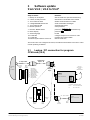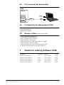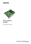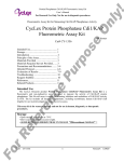
1
CERBERUS® CerGas
Gas warning unit CC60
Parameter setting quick instruction,
software
Fire & Security Products
Siemens Building Technologies Group
Data and design subject to change
without notice. / Supply subject to
availability.
Copyright by
Siemens Building Technologies AG
Wir behalten uns alle Rechte an
diesem Dokument und an dem in ihm
dargestellten Gegenstand vor. Der
Empfänger anerkennt diese Rechte
und wird dieses Dokument nicht ohne
unsere vorgängige schriftliche
Ermächtigung ganz oder teilweise
Dritten zugänglich machen oder
ausserhalb des Zweckes verwenden,
zu dem es ihm übergeben worden ist.
We reserve all rights in this document
and in the subject thereof. By
acceptance of the document the
recipient acknowledges these rights
and undertakes not to publish the
document nor the subject thereof in
full or in part, nor to make them
available to any third party without our
prior express written authorization,
nor to use it for any purpose other
than for which it was delivered to him.
Nous nous réservons tous les droits
sur ce document, ainsi que sur l’objet
y figurant. La partie recevant ce
document reconnaît ces droits et elle
s’engage à ne pas le rendre
accessible à des tiers, même
partiellement, sans notre autorisation
écrite préalable et à ne pas
l’employer à des fins autres que
celles pour lesquelles il lui a été
remis.
Ci riserviamo ogni diritto relativo al
presente documento e sull’oggetto
illustrato in esso. La parte che riceve
il documento si impegna a non
renderlo accessibile a terzi, né per
intero né in parte, senza la nostra
previa autorizzazione scritta ed a non
usarlo per altri scopi di quello per il
quale è stato rilasciato.
About this document . . . . . . . . . . . . . . . . . . . . . . . . . . . . . . . . . . . . . . . . . . . . . . . . . . . .
1
1
1.1
1.2
1.3
1.4
1.5
Parameter setting SW version 1.05 . . . . . . . . . . . . . . . . . . . . . . . . . . . . . . . . .
ln general . . . . . . . . . . . . . . . . . . . . . . . . . . . . . . . . . . . . . . . . . . . . . . . . . . . . . . . . .
Function level F1 . . . . . . . . . . . . . . . . . . . . . . . . . . . . . . . . . . . . . . . . . . . . . . . . . . .
Function level F2 . . . . . . . . . . . . . . . . . . . . . . . . . . . . . . . . . . . . . . . . . . . . . . . . . . .
Function level F3 . . . . . . . . . . . . . . . . . . . . . . . . . . . . . . . . . . . . . . . . . . . . . . . . . . .
Function level F4 . . . . . . . . . . . . . . . . . . . . . . . . . . . . . . . . . . . . . . . . . . . . . . . . . . .
2
2
2
2
3
4
2
Function comparison . . . . . . . . . . . . . . . . . . . . . . . . . . . . . . . . . . . . . . . . . . . . . .
6
3
3.1
Software update from V3.X / V4.0 to V5.0* . . . . . . . . . . . . . . . . . . . . . . . . . . .
Laptop / PC connection for program CC60.exe (V4.0) . . . . . . . . . . . . . . . . . . .
7
7
4
New functions in software version 5.0* . . . . . . . . . . . . . . . . . . . . . . . . . . . . .
8
5
5.1
New calibration Sensors Generation 60 . . . . . . . . . . . . . . . . . . . . . . . . . . . . . .
New calibration automatic Sensors Generation 61 . . . . . . . . . . . . . . . . . . . . . .
8
8
6
6.1
6.2
6.3
6.4
Data backup with SWE60 . . . . . . . . . . . . . . . . . . . . . . . . . . . . . . . . . . . . . . . . . .
Required hardware . . . . . . . . . . . . . . . . . . . . . . . . . . . . . . . . . . . . . . . . . . . . . . . . .
PC connection for data backup . . . . . . . . . . . . . . . . . . . . . . . . . . . . . . . . . . . . . . .
Configuration for data backup (CC60) . . . . . . . . . . . . . . . . . . . . . . . . . . . . . . . . .
Backup of data . . . . . . . . . . . . . . . . . . . . . . . . . . . . . . . . . . . . . . . . . . . . . . . . . . . . .
8
8
9
9
9
7
Details for ordering Software CC60 . . . . . . . . . . . . . . . . . . . . . . . . . . . . . . . . .
9
I
Fire & Security Products
Siemens Building Technologies Group
05.2002
II
Fire & Security Products
Siemens Building Technologies Group
05.2002
About this document
Purpose
This document defines the parameter settings of CC60 gas warning units in a shortened
form and is a supplement to other reference documents.
Software updates and data backups are described in the second part of the document.
Scope
The available document applies to the commissioning personnel, responsible for the commissioning and maintenance of CC60 gas warning units. For a complete commissioning
additional reference documents are necessary.
Reference documents
Gas warning unit CC60
785 Parameter settings
Softwaretool SWE60
1369 User manual
Standard symbols
Input
A
Indicate
D
Push
Abbreviations
W
Warning
P
Prealarm
A
Alarm
F
Fault
LMS
Local monitoring system
CAC
Cerberus alarm concept
DMS
Danger management system
Modifications
Version
Date
Description
e1989
04. 2000
New, replaces documents 1434 and 1513
User functions user–friendly arranged
Software versions 3.7, 4.0 omitted
Technical data updated
e1989a
05.2002
new layout, Autocal.
1
Fire & Security Products
Siemens Building Technologies Group
e1989b
05.2002
1
Parameter setting SW version 1.05
1.1
ln general
RESET–functions
Hardware RESET . . . . . . . . . . . . . . . . . . . . . . . . . . . . . . . . . . . . . . .
RAM RESET . . . . . . . . . . . . . . . . . . . . . . . . . . . . . . . . . . . . . . . . . . . . . .
Master RESET . . . . . . . . . . . . . . . . . . . . . . . . . . . . . . . . . . . . . . . . . . .
1.2
Keys
0+8
0+2+5+8
[I] + 2 + 6 +1 + 9
Function level F1
001 – 414 . . . . . . . . . . . . . . . . . . . . . . Detector OFF / ON
500 . . . . . . . . . . . . . . . . . . . . . . . . . . . . . . . A Software version
510 – 551 . . . . . . . . . . . . . . . . . . . . . . A latest 5 ”first alarm”
560 . . . . . . . . . . . . . . . . . . . . . . . . . . . . . . . D latest 5 ”first alarm”
640 / 650 . . . . . . . . . . . . . . . . . . . . . . A Installation / replacement date of sensor
670 / 680 . . . . . . . . . . . . . . . . . . . . . . A Last / next calibration date
720 . . . . . . . . . . . . . . . . . . . . . . . . . . . . . . . Printer ON / OFF
990 . . . . . . . . . . . . . . . . . . . . . . . . . . . . . . . Lamptest ON / OFF
1.3
Function level F2
001 – 414 . . . . . . . . . . . . . . . . . . . . . . Detector OFF / ON
500 . . . . . . . . . . . . . . . . . . . . . . . . . . . . . . . Relay test fault
510 – 530 . . . . . . . . . . . . . . . . . . . . . . Relay test W / P / A (Gr no)
540 . . . . . . . . . . . . . . . . . . . . . . . . . . . . . . . Relay test alarm horn, SU Relay 4
550 . . . . . . . . . . . . . . . . . . . . . . . . . . . . . . . Relay test alarm with timer, SU Relay 3
560 . . . . . . . . . . . . . . . . . . . . . . . . . . . . . . . Relay test remote alarm, SU Relay 2
600 . . . . . . . . . . . . . . . . . . . . . . . . . . . . . . . Simulation detector fault
610 – 630 . . . . . . . . . . . . . . . . . . . . . . Simulation detector W / P / A
640 . . . . . . . . . . . . . . . . . . . . . . . . . . . . . . . Switch off simulation
700 . . . . . . . . . . . . . . . . . . . . . . . . . . . . . . . A Check sum EPROM program
710 – 720 . . . . . . . . . . . . . . . . . . . . . . A Check sum EPROM configuration / text
2
Fire & Security Products
Siemens Building Technologies Group
e1989b
05.2002
1.4
Function level F3
Date
Time
Functions of time
010 / 020 . . . . . . . . . . . . . . . . . . . . . . Date / time
Weekday
Code
Monday, Tuesday, Wednesday, ...
1, 2, 3, ...
Sunday
0
030 . . . . . . . . . . . . . . . . . . . . . . . . . . . . . . . Commissioning Date
040 . . . . . . . . . . . . . . . . . . . . . . . . . . . . . . . Switchover time day / night
045 . . . . . . . . . . . . . . . . . . . . . . . . . . . . . . . Expired dates activate a fault indication
050 . . . . . . . . . . . . . . . . . . . . . . . . . . . . . . . Switchover winter– / summertime
060 . . . . . . . . . . . . . . . . . . . . . . . . . . . . . . . Switchover summer– / wintertime
070 / 080 . . . . . . . . . . . . . . . . . . . . . . Investigation time V1 / V2
085 . . . . . . . . . . . . . . . . . . . . . . . . . . . . . . . Warning before expire V2
090 . . . . . . . . . . . . . . . . . . . . . . . . . . . . . . . Duration time external acoustic SU Relay 3
Detector datas
100 / 110 . . . . . . . . . . . . . . . . . . . . . . Detector selection select / remove
120 / 130 . . . . . . . . . . . . . . . . . . . . . . Reference detector / copie datas
140 – 450 . . . . . . . . . . . . . . . . . . . . . . Optional commands available, only when activated (release
in F4 880). Input after F4
900 . . . . . . . . . . . . . . . . . . . . . . . . . . . . . . . Selection of language
(for collective programming)
Language
Password
910 . . . . . . . . . . . . . . . . . . . . . . . . . . . . . . Disable/release VD60 display for interrogation
920 – 940 . . . . . . . . . . . . . . . . . . . . . . Password Switching–off delay 4–99 minutes
950 – 970 . . . . . . . . . . . . . . . . . . . . . . Password level 0,1 and 2
3
Fire & Security Products
Siemens Building Technologies Group
e1989b
05.2002
1.5
System datas
Function level F4
010 / 015 . . . . . . . . . . . . . . . . . . . . . . Network
Computer connection / location
address
Release / rates in baud
Release / rates in baud
Release / rates in baud
020 / 025 . . . . . . . . . . . . . . . . . . . . . . Printer
030 / 035 . . . . . . . . . . . . . . . . . . . . . . Remote control
040 / 045 . . . . . . . . . . . . . . . . . . . . . . Service PC
050 – 080 . . . . . . . . . . . . . . . . . . . . . . Construction control unit
LI60–02
non–existent . . . . . . . . . . . . . . . . . . . . . . . . . . . . . . . . . . . . .
stub line, locally supplied . . . . . . . . . . . . . . . . . . . .
stub line, remote supplied . . . . . . . . . . . . . . . . . . .
loop line, locally supplied . . . . . . . . . . . . . . . . . . . .
loop line, remote supplied . . . . . . . . . . . . . . . . . . .
Module type
none . . . . . . . . . . . . . . . . . . . . . . . . . . . . . . . . . . . . . . . . . . . . . . . .
RK60 . . . . . . . . . . . . . . . . . . . . . . . . . . . . . . . . . . . . . . . . . . . . . . .
E4G020 (16 out) . . . . . . . . . . . . . . . . . . . . . . . . . . . . . . . .
AK60 . . . . . . . . . . . . . . . . . . . . . . . . . . . . . . . . . . . . . . . . . . . . . . .
E4G040 (16 in) . . . . . . . . . . . . . . . . . . . . . . . . . . . . . . . . .
E4G030 (12 in / 4 out) . . . . . . . . . . . . . . . . . . . . . . . .
Code
0
1
2
5
6
Code
0
1
2
5
6
7
Detector datas
100 . . . . . . . . . . . . . . . . . . . . . . . . . . . . . . . Address (link’s)
130 . . . . . . . . . . . . . . . . . . . . . . . . . . . . . . . A Address (link’s)
140 / 150 . . . . . . . . . . . . . . . . . . . . . . . Date
physical logical
logical physical
Commissioning / sensor exchange
Calibration functions
160 . . . . . . . . . . . . . . . . . . . . . . . . . . . . . . . Master calibration deletion
170 / 180 . . . . . . . . . . . . . . . . . . . . . . . A Date of calibration
last / next
190 . . . . . . . . . . . . . . . . . . . . . . . . . . . . . . . Start calibration
195 . . . . . . . . . . . . . . . . . . . . . . . . . . . . . . . Store calibration
200 . . . . . . . . . . . . . . . . . . . . . . . . . . . . . . . Sensor type
205 . . . . . . . . . . . . . . . . . . . . . . . . . . . . . . . Sensitivity (70%) for recalibration
210 . . . . . . . . . . . . . . . . . . . . . . . . . . . . . . . Concentration of first calibration gas
220 . . . . . . . . . . . . . . . . . . . . . . . . . . . . . . . Concentration of second calibration gas
Evaluation
225 . . . . . . . . . . . . . . . . . . . . . . . . . . . . . . . Start display
(Supression of bar indicator)
230 – 240 . . . . . . . . . . . . . . . . . . . . . . Display of bar indicator Start/End/Inversion
245 . . . . . . . . . . . . . . . . . . . . . . . . . . . . . . . Inversion of detector function
250 – 270 . . . . . . . . . . . . . . . . . . . . . . Analogue output
Start/End/Adress
300 – 320 . . . . . . . . . . . . . . . . . . . . . . Treshold value
W/P/A
350 – 380 . . . . . . . . . . . . . . . . . . . . . . Programming self hold P / W / P / A
410 – 414 . . . . . . . . . . . . . . . . . . . . . . Fault
Enable / Print / LMS
420 – 424 . . . . . . . . . . . . . . . . . . . . . . Warning
Enable / Print / LMS
430 – 434 . . . . . . . . . . . . . . . . . . . . . . Prealarm
Enable / Print / LMS
440 – 444 . . . . . . . . . . . . . . . . . . . . . . Alarm
Enable / Print / LMS
450 . . . . . . . . . . . . . . . . . . . . . . . . . . . . . . . Detector
Enable (ON/OFF)
480 . . . . . . . . . . . . . . . . . . . . . . . . . . . . . . . Enable functionality for F1 and F2
0 = F1 and F2 with password level 0 (default 7000 resp. system number)
1 = F1 and F2 with password level 1, (default 7100)
490 . . . . . . . . . . . . . . . . . . . . . . . . . . . . . . . Display supression in % of the warning level ( for all sensors
at the same time active)
4
Fire & Security Products
Siemens Building Technologies Group
e1989b
05.2002
Operating functions
(Groups)
500
Assignment of control groups
Event level [Flag]
Code
Warning . . . . . . . . . . . . . . . . . . . . . . . . . . . . . . . . . . . . . . . . . . . [1]
Pre–alarm . . . . . . . . . . . . . . . . . . . . . . . . . . . . . . . . . . . . . . . . [2]
[1] + [2] . . . . . . . . . . . . . . . . . . . . . . . . . . . . . . . . . . . . . . . . . . . . [3]
Alarm . . . . . . . . . . . . . . . . . . . . . . . . . . . . . . . . . . . . . . . . . . . . . . . [4]
[4] + [1] . . . . . . . . . . . . . . . . . . . . . . . . . . . . . . . . . . . . . . . . . . . . [5]
[4] + [2] . . . . . . . . . . . . . . . . . . . . . . . . . . . . . . . . . . . . . . . . . . . . [6]
[1] + [2] + [4] . . . . . . . . . . . . . . . . . . . . . . . . . . . . . . . . . . . . . [7]
510 . . . . . . . . . . . . . . . . . . . . . . . . . . . . . . . Group dependency (2,3,..)
520 / 525 / 526 . . . . . . . . . . . . . . . Enable printing
W/P/A
530 / 535 . . . . . . . . . . . . . . . . . . . . . . . Enable to LMS
W/P
550 / 560 . . . . . . . . . . . . . . . . . . . . . . . Delay time
ON / OFF
600 . . . . . . . . . . . . . . . . . . . . . . . . . . . . . . . Select output code
610 / 620 . . . . . . . . . . . . . . . . . . . . . . . Assignment of relay W INDICATION / INPUT
630 / 640 . . . . . . . . . . . . . . . . . . . . . . . Assignment of relay P INDICATION / INPUT
650 / 660 . . . . . . . . . . . . . . . . . . . . . . . Assignment of relay A INDICATION / INPUT
700 – 720 . . . . . . . . . . . . . . . . . . . . . . Relay self holding
W/P/A
800 . . . . . . . . . . . . . . . . . . . . . . . . . . . . . . . Groups ON / OFF
810 / 820 . . . . . . . . . . . . . . . . . . . . . . . Enable relay to
LMS / Printer
850 . . . . . . . . . . . . . . . . . . . . . . . . . . . . . . . A Detector / Groups / Flags
860 . . . . . . . . . . . . . . . . . . . . . . . . . . . . . . . A Relay assignment W / P / A
870 . . . . . . . . . . . . . . . . . . . . . . . . . . . . . . . Splitting [7] in F4 500 for W / P / A
Service functions
880 . . . . . . . . . . . . . . . . . . . . . . . . . . . . . . . Enable functions F3 140 – F3 450
890 . . . . . . . . . . . . . . . . . . . . . . . . . . . . . . . Hierarchy level function F1 u. F2
900 . . . . . . . . . . . . . . . . . . . . . . . . . . . . . . . Mains filter 50 / 60 Hz
905 . . . . . . . . . . . . . . . . . . . . . . . . . . . . . . . Response time delay on mains failure
910 / 920 . . . . . . . . . . . . . . . . . . . . . . . D System datas / Configuration
930 . . . . . . . . . . . . . . . . . . . . . . . . . . . . . . . D Functional condition
Service functions
940
...............................
D Memory
Event level [Flag]
Code
Operating message . . . . . . . . . . . . . . . . . . . . . . . . . . . [1]
Manipulation . . . . . . . . . . . . . . . . . . . . . . . . . . . . . . . . . . . . . [2]
[1] + [2] . . . . . . . . . . . . . . . . . . . . . . . . . . . . . . . . . . . . . . . . . . . . [3]
Fault message . . . . . . . . . . . . . . . . . . . . . . . . . . . . . . . . . . [4]
[4] + [1] . . . . . . . . . . . . . . . . . . . . . . . . . . . . . . . . . . . . . . . . . . . . [5]
[4] + [2] . . . . . . . . . . . . . . . . . . . . . . . . . . . . . . . . . . . . . . . . . . . . [6]
[1] + [2] + [4] . . . . . . . . . . . . . . . . . . . . . . . . . . . . . . . . . . . . . [7]
950 . . . . . . . . . . . . . . . . . . . . . . . . . . . . . . . D Calibration protocol
Calibration state
uncalibrated
No calibration data present . . . . . . . . . . . . . . . . . . . 0
Null gas measurement not completed . . . . . 1
Trigger operation not given . . . . . . . . . . . . . . . . . . . 2
Drop criteria not fulfilled . . . . . . . . . . . . . . . . . . . . . . . . 3
Minimum increase at first
calibration not achieved . . . . . . . . . . . . . . . . . . . . . . . . 4
Insufficient sensitivity at post–calibration . 5
calibrated
Data minimum increase from
master calibration . . . . . . . . . . . . . . . . . . . . . . . . . . . . . . . . 6
New calibration record . . . . . . . . . . . . . . . . . . . . . . . . . 7
970 . . . . . . . . . . . . . . . . . . . . . . . . . . . . . . . Repeated indicating of detector address
980 . . . . . . . . . . . . . . . . . . . . . . . . . . . . . . . A Detector measured values on detector line
...............................
5
Fire & Security Products
Siemens Building Technologies Group
e1989b
05.2002
2
Function comparison
System datas
SWE60
Function no.
CT60
Selection of language . . . . . . . . . . . . . . . . . . . . . . . . . F3 900
Mains filter . . . . . . . . . . . . . . . . . . . . . . . . . . . . . . . . . . . . . . . . F4 900
Passwort Ebenen / Gültigkeit . . . . . . . . . . . . . . . F3 920 – 970
Disable/release VD60 display . . . . . . . . . . . . . . F3 910
System time / Date . . . . . . . . . . . . . . . . . . . . . . . . . . . . . F3 010 / 020
Switchover time day / night . . . . . . . . . . . . . . . . . . F3 040
Switchover summer / winter . . . . . . . . . . . . . . . . . F3 050 / 060
Investigation time CAC . . . . . . . . . . . . . . . . . . . . . . . F3 070 – 090
Delay on mains failure . . . . . . . . . . . . . . . . . . . . . . . . F4 905
Expired dates fault indication . . . . . . . . . . . . . . . F3 045
Hardware
Bus . . . . . . . . . . . . . . . . . . . . . . . . . . . . . . . . . . . . . . . . . . . . . . . . . . F4 070
Display element . . . . . . . . . . . . . . . . . . . . . . . . . . . . . . . . . F4 050
Fire brigade operation . . . . . . . . . . . . . . . . . . . . . . . . . F4 080
Interface
Service PC . . . . . . . . . . . . . . . . . . . . . . . . . . . . . . . . . . . . . . . . F4 040
Printer . . . . . . . . . . . . . . . . . . . . . . . . . . . . . . . . . . . . . . . . . . . . . . F4 020
Remote control . . . . . . . . . . . . . . . . . . . . . . . . . . . . . . . . . . F4 030
Management system . . . . . . . . . . . . . . . . . . . . . . . . . . F4 010
Detectorline
LI 60
Detector parameter
Assignment Detector FE . . . . . . . . . . . . . . . . . . . . . F4 100
Configuration display bar indicator . . . . . . . . F4 230 – 240
Programming self hold . . . . . . . . . . . . . . . . . . . . . . . . F4 350 – 380
Enable detector configuration . . . . . . . . . . . . . . F4 450
– Master calibration deletion . . . . . . . . . . . . . . . . F4 160
– Sensitivity . . . . . . . . . . . . . . . . . . . . . . . . . . . . . . . . . . . . . . . F4 205
– 1st commissioning (only display) . . . . . . . . F4 140
– Next exchange . . . . . . . . . . . . . . . . . . . . . . . . . . . . . . . . F4 150
– Last Calibration . . . . . . . . . . . . . . . . . . . . . . . . . . . . . . . F4 170
Inversion of alarms . . . . . . . . . . . . . . . . . . . . . . . . . . . . . F4 245
– F / W / P / A Print / DMS . . . . . . . . . . . . . . . . . . F4 410 – 444
Enable Detector . . . . . . . . . . . . . . . . . . . . . . . . . . . . . . . . . F4 410 – 440
Sensor type . . . . . . . . . . . . . . . . . . . . . . . . . . . . . . . . . . . . . . . F4 200
Configuration analogue output . . . . . . . . . . . . . F4 250 – 270
Concentration calibration gas . . . . . . . . . . . . . . . F4 210 – 220
Configuration treshold value . . . . . . . . . . . . . . . . F4 300 – 320
Copie functions
Copie detector functions
Control zones
Detector assignment . . . . . . . . . . . . . . . . . . . . . . . . . . F4 500 – 510
Relay assignment . . . . . . . . . . . . . . . . . . . . . . . . . . . . . . F4 610 – 820
Delay time ON / OFF . . . . . . . . . . . . . . . . . . . . . . . . . . F4 550 – 560
Relay self holding . . . . . . . . . . . . . . . . . . . . . . . . . . . . . . . F4 700 – 720
Group status, relay to LMS / Printer . . . . . . F4 800 – 820
. . . . . . . . . . . . . . . . . . . . . . . . . . . . . . . . . . . . . . . . . . . . . . . . F4
. . . . . . . . . . . . . . . . . . . . . F3
/
/
/
/
045
025
035
015
060
100 – 130
6
Fire & Security Products
Siemens Building Technologies Group
e1989b
05.2002
3
Software update
from V3.X / V4.0 to V5.0*
Steps to follow:
1. Backup of old System
2. Check, if backup file has
3. Turn CC60 unit OFF
4. Change EPROM U2 and U3
5. Turn CC60 unit ON
6. Enable operation
Remarks:
with old CC60.exe (and old software key)
with Norton Commander been created
disable communication to outside
avoid electrostatic discharges
acknowledge buzzer
enter password
7. Execute ”Master Reset”
press keys
8. Erase display
9. Select language
10. F4 040 ON
11. F4 045 ON
12. Reload System data to CC60 unit
press key C
F3 900
configure output for PC devices to ”ON”
program baud rates to 9600
with old CC60.exe
2
6
1
9
simultaneously
The CC60 unit is now configured as before, but with the new software. The unit is ”under
normal operating conditions”.
3.1
Laptop / PC connection for program
CC60.exe (V4.0)
RS232 Cable
25pin F / M
9 – 25pin Cable
Laptop/
PC
(COM1)
Female
Socket
DB9
Male
Plug
DB25
1
2
3
4
5
6
7
8
9
8
3
2
20
7
6
4
5
2
.
.
.
25
CD
RD
TD
DTR
SG
DSR
RTS
CTS
RI
Set the
switches to
send,
downwards!
Gas
Adaptor
25pin
Description
Carrier detect
Received data
Transmitted data
Data terminal ready
Signal ground
Data set ready
Request to send
Clear to send
Ring indicator
V24 Dual–Modem Z3W050 /
Z3W051
Input K1
25pin Connector
S1
A2 A1
S2
Connect 14pol flatcable
Cable−
side
1
2
3
4
5
6
7
8
.
.
.
25
.
1
2
3
4
5
6
7
8
.
.
.
25
.
Female
Socket
DB25
Male
Plug
DB25
from
A1 of modem box
to
P5 of SU−60
Modem B3D021
25 − 9pin Cable
Modem−
side
25pin
Female
Input
9pin Connector
9pin
Male
7
Fire & Security Products
Siemens Building Technologies Group
e1989b
05.2002
4
New functions in software
version 5.0* (See Document e4708)
F3 225
Suppression of the display below the selected value (absolute value)
F4 190
F4 195
F4 205
F4 225
F4 490
F4 950
Activate calibration
Storing the calibration
Sensitivity
Suppression of the display below the selected value (absolute value)
Suppression of the display in % of the lowest alarm level for all sensors together
Print calibration log
5
New calibration Sensors Generation 60
(See Document e4708)
F4
F4
F4
F4
F4
F4
F4
160,
140,
200,
205,
210,
220,
190,
set all sensors on status calibration OFF
check first commissioning
check type of sensor
check the sensitivity value
check concentration of gas 1
check concentration of gas 2
activate calibration
Gasing of sensors with the calibration gas
F4 195, store the calibration
F4 905, set Mains failure response time
F4 950, print the calibration log (Calibration state has to be 7)
5.1
New calibration automatic Sensors Generation 61
(See dokument e4708)
6
Data backup with SWE60
6.1
Required hardware
Modem box B3D 021
14–core ribbon cable
9/9–core RS232 cable
Special software key M3C060
505259
316273
438842
462075
8
Fire & Security Products
Siemens Building Technologies Group
e1989b
05.2002
6.2
PC connection for data backup
CC60
SU 60
M3C060
Parallelport
P5
PC
RS232C
Com1
P4
Printer
6.3
Modem
Configuration for data backup (CC60)
Enable operation, password 7000
F4 040 service PC ON
F4 045 baud rate 9600
6.4
1.
2.
3.
4.
5.
6.
7.
8.
7
Backup of data (See Document e1369)
Save system datas on floppy disc
Start SWE60 tool; With software key
Menu ”File/New”; Create a new file
Menu ”File/Save”; Save new file
Menu ”Control unit ”; Transfer data to disk (CC––>SWE)
Menu ”File/Open”; Open saved data
Menu “File/Create List”; Choose appropriate printer output
Check the print out; Leave one copy at the CC60 unit
Details for ordering Software CC60
Designation
Checksum
Remarks
Part no
EPROM U2 SE60 CCG00105–19
F51C
System software
507626
EPROM U3 TED60 ECG00105–19
5348
German / English
507639
EPROM U3 TED60 ECG10105–19
E5ED
French / English
507642
EPROM U3 TED60 ECG10105–19
1D26
Italien / English
531977
EPROM U3 TED60 ECGE0105–19
0AF1
Spanish / English
531980
9
Fire & Security Products
Siemens Building Technologies Group
e1989b
05.2002
Siemens Building Technologies AG
Alte Landstrasse 411
CH8708 Männedorf
Phone +41 1 − 922 61 11
Fax +41 1 − 922 64 50
www.cerberus.ch
10
Fire
& Security
Document
no. Products
e1989b
Siemens Building Technologies Group
Edition 05.2002
Back
CG60
05.2002
Section
5
Manual