1
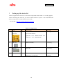
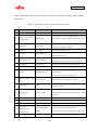
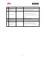
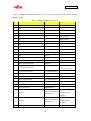
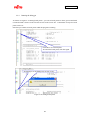
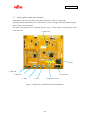
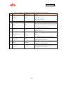
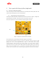
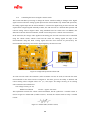
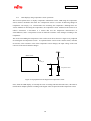
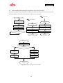
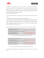
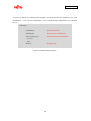
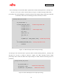
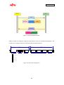
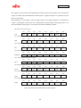
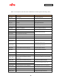
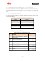
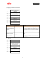
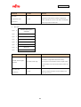
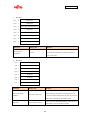
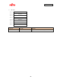
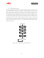
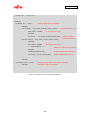
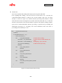
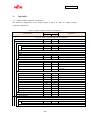
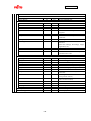
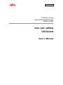
AN07-00200-03E
The registers used for entire LIN communication control on the microcontroller are as described in
“Figure 5-8 Entire LIN communication control registers”. Registers named “res” cannot be used as
they are reserved bits.
The description of each register, and the setting values in the sample programs, are described in
“Table 5-1 Description of the entire LIN communication control registers and setting values”. For
more information of the registers, refer to the microcontroller hardware manual.
LIN-UART serial control register
SCR
bit7
bit6
bit5
bit4
bit3
bit2
bit1
bit0
PEN
P
SBL
CL
AD
CRE
RXE
TXE
LIN-UART serial mode register
SMR
bit7
bit6
bit5
bit4
bit3
bit2
bit1
bit0
MD1
MD0
OTO
EXT
REST
UPCL
SCKE
SOE
LIN-UART serial status register
SSR
bit7
bit6
bit5
bit4
bit3
bit2
bit1
bit0
PE
ORE
FRE
RDRF
TDRE
BDS
RIE
TIE
bit4
bit3
bit2
bit1
bit0
LIN-UART data receiving register / data send register
bit7
bit6
bit5
RDR/TDR
LIN-UART expanded status control register
ESCR
bit7
bit6
bit5
bit4
bit3
bit2
bit1
bit0
LBIE
LBD
LBL1
LBL0
SOPE
SIOP
CCO
SCES
LIN-UART expanded communications control register
ECCR
bit7
bit6
bit5
bit4
bit3
bit2
bit1
bit0
res
LBR
MS
SCDE
SSM
res
RBI
TBI
bit4
bit3
bit2
bit1
bit0
bit4
bit3
bit2
bit1
bit0
LIN-UART baud rate generator register 1
bit7
BGR1
bit6
bit5
‐
LIN-UART baud rate generator register 0
bit7
bit6
bit5
BGR0
Figure 5-8 Entire LIN communication control registers
89