1
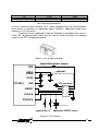
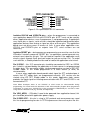
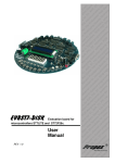
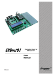
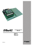
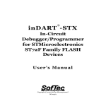
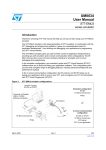
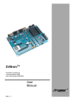
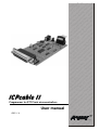
Programmer for ST7 Flash microcontrollers
User manual
REV 1.0
,
lu ard ST Sta rve
a
,
e
o
Ev B VR ers b S l
d
n
io 1, A trol We mo
t
i
a ‘5
in ron ed
r
c
fo cro dd s M the
e
s
d e
i
m mb oar rs, peC E B
e S
PI its ng roll gh r
K pi nt Hi fo
r
y
o
rte tot roc FID ers s
o c
r
Pr mi s, R mm lle
rs or ler gra tro
f ol
n
o
s
pr oco CB
e ntr
l
u o
m icr s, P for
c
e
t
t
m m ds
s
e
ne Sy T
st oar lS
n
y
I
,
s
B tro
C
d
I
r
n
e P
o tio con eb
s
,
R ce lua cro W
V
A pro va mi ed iro g E IC edd m
c
i
s
M nin T, P mb rd ,
a s
g
si , S its E Bo ller
e
d VR K ng ro
A ter pi
nt igh
,
y
o
r
t
1
H
‘5 Sta oto roc ID c
r
e
rs P mi RF m
e
s
l
,
r
er fo ers ram trlv
g n
r
s
ll
Se ule tro pro oco
od con ms icr s,
m
ni net ste T m stem
er Sy , S sy Bo
h
et d In PIC sor on e
, ce ati
ic
e
R
m
o
u
Sp AV opr val IC e
r r
fo ic g E T, P mb
rs s M nin , S
E g
s
r
t
g
R
i
i
in
le
ol des , AV er K typ
B `51 tart roto roS s P mic ,
PC for
s
s ller
er for llers
d
ar tro erw les tro on b S du con ram
c
ro We imo et rog p co
d in ern
e
o
M
m
dd ds eth ste icr
ar rs, Sy T m r
o
B olle In , S so
tr ed IC oce ign
P
s
co Spe R, opr De
V cr
h
B Rtion
ig r A Mi
C
a
H f o rs
, Pone asolution
lu
Many ideas
s
e
s
l
v s
m
er ol
m ntr ste g E ard
co Sy nin Bo
1. Introduction
ICPcable II was made with thought about developers which need low-price
programmer to get start developing applications with ST7Lite, ST7SuperLite and
ST7Dali microcontrollers.
This programmer is simply hardware interface between microcontroller and
developer’s host PC, when using ST7 Visual Programmer (STVP7) or ST7 Visual
Develop (STVD7) software.
We wish you a lot of success and full satisfaction, while using
ICPcable II
2
2. Host PC system requirements
ICPcable II and ST7 Toolset software have been designed to work with PCs
meeting the following requirements:
- One of the following operating systems: Microsoft Windows 98, 2000,
Millennium, NT or XP
-
Intel Pentium (or compatible) processor with minimum speed of 133 MHz.
-
Minimum RAM of 32 MB (64 MB recommended).
-
50 MB of free hard disk space to install all of the ST7 tools.
-
Parallel port
3. Delivery checklist
- ICPcable II programmer
- One 10-pin HE10 type ribbon cable for ICC connectors.
- CD-ROM containing ST7 Toolset
4. Connecting programmer to user application
ICPcable II programmer should be connected directly to PC parallel port or
through LPT cable (input current I/O pin is between 0,5-5mA). ICC cable should be
connected to ICC connectors on programmer and user application. The programmer
is powered from external power supply (12-15V).
On the programmer board is placed 6-pins header to control buffers power
supply, developer can set jumper in one of three positions:
-
connected pins 1 and 2: The power supply voltage of the STICK’s ICC
buffer follows the VDD used by user ST7. This position allows working with
any power supply voltage supported by user MCU. When the jumper is in
this position, user must connect the application power supply to pin 7 of the
ICC connector.
-
connected pins 3 and 4: The power supply voltage of the STICK’s ICC
buffer is 5 V. User don’t need to connect the application VDD to pin 7 of the
ICC connector, but application must be powered by 5 V +/- 5%.
-
connected pins 5 and 6: The power supply voltage of the STICK’s ICC
buffer is 3.3 V. User don’t need to connect the application VDD to pin 7 of
the ICC connector, but application must be powered by 3.3 V +/- 5%.
3
MCU supply voltage
5V
3.3V
STICK supply current (min)
15mA
12mA
STICK supply current (max)
40mA
25mA
Tab 1. Electrical characteristic
In-Circuit Communication protocol (ICC) allows programming the microcontroller
while device is mounted on application board. However, application board must
integrate an ICC connector.
To connect to user application board for ICPcable II, developer must install a
10-pin, HE-10 type connector, which receives the ICC cable and relays the required
signals to the ST7 on application board.
Figure.1. HE-10 type connector
Application power supply
VDD
OSC1/
CLKIN
OSC2
ST7 MCU
optional
XTAL1
C2
C1
VSS
ICC connector
10
8
6
4
2
/RESET
ICCCLK
ICCDATA
R1
application I/O
R2
9
7
5
3
1
D1
Schottky diode
application RESET source
Figure.2. ICC Interface
4
ICC connector
GND
ICCSEL/VPP
ICCRESET
ICCCLK
ICCDATA
10
8
6
4
2
9
7
5
3
1
ICCOSC
VDD_APPLI
GND
GND
GND
Figure.3. Pin specification for ICC connector
Isolation ICCCLK and ICCDATA pins – when the programmer is connected to
user application board ICCCLK and ICCDATA pins of ST7 must not be used by
others application devices, even if programmer is not programming. If application
uses these pins as inputs, serial resistors should be implemented to prevent other
application devices from forcing a signal on either of these pins. The application
board must not drive current in excess of 1mA. In case when application uses
ICCCLK and ICCDATA pins as outputs from ST7, serial resistors are not
necessary.
Isolation RESET pin – during processor programming user must be sure that the
ICPcable II controls processor RESET pin, so application cannot generate any
external reset signal on this pin. This can lead to a conflict if the application reset
circuitry signal exceeds 5mA (push-pull output or pull-up resistor <1k). To avoid
such conflicts, a Shottky diode can be used to isolate the application reset circuit.
Pin ICCOSC – this ICC connector pin should be connected to OSC1 or OSCIN
pin, if clock is not provided by the application or if clock source is not programmed
in option byte. This connection allows starting programming session in ICP OPT
Disable mode. In this mode programmer is a clock source (8 MHz) for
microcontroller.
In case, when application board provide clock signal for ST7 and developer is
certain that ST7 option byte are programmed correctly, ICP session can be
started using ICP OPT Enable mode. In this mode, application clock source
provides the clock signal for initiating communication with ST7 and ICCOSC is not
connected to ST7.
Note: When developer wants to use ICCOSC as clock source for microcontroller during
programming, he should read first datasheet of this microcontroller (chapter about programmer
connection). In some case, ICCOSC has to be connected to PB4/CLKIN pin, not OSC1, when
using ICP OPT Disable mode (e.g. ST7Lite, ST7SuperLite).
Pin VDD_APPLI – ICPcable II need to be powered from application board, this
pin should be joined with application power supply.
Pin ICCSEL/VPP – this pin is using in ICC protocol and some processors need
this line to programming session. In ST7Lite processors there are no pins like this.
5
5. Programming with STVD7 or STVP7
Developer can configure and control the programming of ST7 with ST7 Visual
Programmer (STVP7) or ST7 Visual Develop (STVD7) software running on host
PC.
Start programming with STVD7
1 Launch STVD7
2 Open workspace and project that you used when developing your application.
You will have selected your MCU during the early stages of application
development.
3 Select Tools>Programmer.
4 Configure the options in the Settings tab:
- Board: Stick
- Port: LPT1 or LPT2
- Programming mode:
- ICP OPT Disable– a safe mode that must be used if your
application clock circuitry doesn’t match the OSCTYPE option byte
selection. In this mode, an external source with a square wave signal
from 0 V to VDD must be provided either by the ICPcable II via the
ICC connector pin 9 (ICCOSC safe clock), or your application.
- ICP OPT Enable – used only if your application clock circuitry
matches the OSCTYPE option byte selection. In this case, the ICC
connector pin 9 is not connected and the ICCOSC safe clock is not
used.
5 Power on your application board and connect the ICC cable between your
ICPcable II and the application.
6 Select the Memory Area tab then select a memory area. Click on Add and
then use the browse window to identify the file (.s19, .hex) to program the
selected memory area with. Repeat this step as necessary for each memory
area.
7 Select the Option Byte tab to configure any option byte settings.
8 Select the Program tab and click on Start to program your ST7.
6
Start programming with STVP7:
1 Lunch STVP7
2 Select Configure>Configure ST Visual Programmer:
- Hardware: STICK
- Port: LPT1 or LPT2
- Programming mode:
- ICP OPT Disable– a safe mode that must be used if your
application clock circuitry doesn’t match the OSCTYPE option byte
selection. In this mode, an external source with a square wave signal
from 0 V to VDD must be provided either by the ICPcable II via the
ICC connector pin 9 (ICCOSC safe clock), or your application.
- ICP OPT Enable – used only if your application clock circuitry
matches the OSCTYPE option byte selection. In this case, the ICC
connector pin 9 is not connected and the ICCOSC safe clock is not
used.
Select the name of your MCU from the list in the Device field. Keep in
mind that the list displayed for ICP mode is different from that displayed
for the other two in-circuit programming modes.
3 Select files (.s19, .sx, .hex) for programming to memory areas. Select the tab
for the memory area (for example, PROGRAM MEMORY or DATA
MEMORY), then select File>Open. Locate the file using the resulting browse
window and click on Open.
4 Select the Option Byte tab. Option bytes can be configured using the list
boxes in this tab or by loading a HEX or S19 file with the previously used
option byte settings. To program option bytes from a file, select the Option
Byte tab, then click on File>Open to load the file containing the option byte
settings.
5 Program your ST7 by selecting Program>All Tabs (on active sectors, if any)
6 Check the content by selecting Verify>All Tabs (on active sectors, if any). If
you want to check the programmed content systematically after programming,
ensure that the Verify After Programming feature is activated
(Edit>Preferences)
You have to disconnect ICC cable form your application board, then
microcontroller will start.
7
Manufacturer:
„PROPOX”
ul. Korzeniowskiego 30
81-376 Gdynia, Poland
contact: [email protected]
technical support: [email protected]
8