1
UM0313
User manual
EK302DL
Evaluation Kit
Introduction
The EK302DL is an evaluation kit designed to provide the user with a complete, ready-touse platform for evaluation of the LIS302DL. The LIS302DL is a low power 3-axis linear
accelerometer with digital output. The device includes a sensing element and an IC
interface capable of translating information from the sensing element into a measured signal
that can be used for external applications.
In addition to the MEMS sensor, the evaluation board utilizes an ST7-USB microcontroller
which functions as a bridge between the sensor and the PC, on which it is possible to use
the Graphical User Interface included with the kit or dedicated software routines for
customized applications.
This user manual describes the hardware included with the evaluation kit and provides the
information required to install and run the evaluation kit user interface.
For details regarding the features of the LIS302DL sensor, please refer to the datasheet for
this device and application note AN2335.
June 2007
Rev 2
1/33
www.st.com
Contents
UM0313
Contents
1
Evaluation kit description . . . . . . . . . . . . . . . . . . . . . . . . . . . . . . . . . . . . . 5
2
EK302DL GUI installation . . . . . . . . . . . . . . . . . . . . . . . . . . . . . . . . . . . . . 7
3
2.1
PC system requirements . . . . . . . . . . . . . . . . . . . . . . . . . . . . . . . . . . . . . . 7
2.2
Software installation . . . . . . . . . . . . . . . . . . . . . . . . . . . . . . . . . . . . . . . . . . 7
2.3
Hardware installation . . . . . . . . . . . . . . . . . . . . . . . . . . . . . . . . . . . . . . . . . 7
Graphical User Interface . . . . . . . . . . . . . . . . . . . . . . . . . . . . . . . . . . . . . 11
3.1
Connecting to the Virtual COM port . . . . . . . . . . . . . . . . . . . . . . . . . . . . . 12
3.2
“Options” tab . . . . . . . . . . . . . . . . . . . . . . . . . . . . . . . . . . . . . . . . . . . . . . . 12
3.3
“Register Setup” tab . . . . . . . . . . . . . . . . . . . . . . . . . . . . . . . . . . . . . . . . . 13
3.4
“Bars” tab . . . . . . . . . . . . . . . . . . . . . . . . . . . . . . . . . . . . . . . . . . . . . . . . . 15
3.5
“Plot” tab . . . . . . . . . . . . . . . . . . . . . . . . . . . . . . . . . . . . . . . . . . . . . . . . . . 16
3.6
“Data” tab . . . . . . . . . . . . . . . . . . . . . . . . . . . . . . . . . . . . . . . . . . . . . . . . . 17
3.7
“Inclinometer” tab . . . . . . . . . . . . . . . . . . . . . . . . . . . . . . . . . . . . . . . . . . . 18
3.8
“Map Browsing” tab . . . . . . . . . . . . . . . . . . . . . . . . . . . . . . . . . . . . . . . . . 19
3.9
“Interrupt” tab . . . . . . . . . . . . . . . . . . . . . . . . . . . . . . . . . . . . . . . . . . . . . . 19
3.10
“Click” tab . . . . . . . . . . . . . . . . . . . . . . . . . . . . . . . . . . . . . . . . . . . . . . . . . 21
3.11
“FFT” tab . . . . . . . . . . . . . . . . . . . . . . . . . . . . . . . . . . . . . . . . . . . . . . . . . 22
4
Data acquisition quick start . . . . . . . . . . . . . . . . . . . . . . . . . . . . . . . . . . 22
5
EK Lite . . . . . . . . . . . . . . . . . . . . . . . . . . . . . . . . . . . . . . . . . . . . . . . . . . . 23
6
MEMS pointer . . . . . . . . . . . . . . . . . . . . . . . . . . . . . . . . . . . . . . . . . . . . . 24
6.1
7
GUI description . . . . . . . . . . . . . . . . . . . . . . . . . . . . . . . . . . . . . . . . . . . . 24
6.1.1
Right side: main controls . . . . . . . . . . . . . . . . . . . . . . . . . . . . . . . . . . . . 25
6.1.2
Left side: pointer application controls . . . . . . . . . . . . . . . . . . . . . . . . . . 25
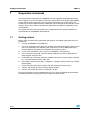
Supported commands . . . . . . . . . . . . . . . . . . . . . . . . . . . . . . . . . . . . . . 26
7.1
Getting started . . . . . . . . . . . . . . . . . . . . . . . . . . . . . . . . . . . . . . . . . . . . . 26
7.2
Supported commands . . . . . . . . . . . . . . . . . . . . . . . . . . . . . . . . . . . . . . . 27
7.2.1
2/33
Start command . . . . . . . . . . . . . . . . . . . . . . . . . . . . . . . . . . . . . . . . . . . 27
UM0313
Contents
7.3
7.2.2
Debug command . . . . . . . . . . . . . . . . . . . . . . . . . . . . . . . . . . . . . . . . . . 27
7.2.3
Stop command . . . . . . . . . . . . . . . . . . . . . . . . . . . . . . . . . . . . . . . . . . . . 28
7.2.4
Register read . . . . . . . . . . . . . . . . . . . . . . . . . . . . . . . . . . . . . . . . . . . . . 28
7.2.5
Register write . . . . . . . . . . . . . . . . . . . . . . . . . . . . . . . . . . . . . . . . . . . . . 28
7.2.6
Single bit write . . . . . . . . . . . . . . . . . . . . . . . . . . . . . . . . . . . . . . . . . . . . 28
7.2.7
Zon and Zoff . . . . . . . . . . . . . . . . . . . . . . . . . . . . . . . . . . . . . . . . . . . . . 28
7.2.8
Device name . . . . . . . . . . . . . . . . . . . . . . . . . . . . . . . . . . . . . . . . . . . . . 28
7.2.9
Firmware version . . . . . . . . . . . . . . . . . . . . . . . . . . . . . . . . . . . . . . . . . . 29
Quick start . . . . . . . . . . . . . . . . . . . . . . . . . . . . . . . . . . . . . . . . . . . . . . . . 29
8
Schematic diagram . . . . . . . . . . . . . . . . . . . . . . . . . . . . . . . . . . . . . . . . . 30
9
Bill of materials . . . . . . . . . . . . . . . . . . . . . . . . . . . . . . . . . . . . . . . . . . . . 31
10
Revision history . . . . . . . . . . . . . . . . . . . . . . . . . . . . . . . . . . . . . . . . . . . 32
3/33
List of figures
UM0313
List of figures
Figure 1.
Figure 2.
Figure 3.
Figure 4.
Figure 5.
Figure 6.
Figure 7.
Figure 8.
Figure 9.
Figure 10.
Figure 11.
Figure 12.
Figure 13.
Figure 14.
Figure 15.
Figure 16.
Figure 17.
Figure 18.
Figure 19.
Figure 20.
Figure 21.
Figure 22.
Figure 23.
Figure 24.
4/33
Evaluation board block diagram . . . . . . . . . . . . . . . . . . . . . . . . . . . . . . . . . . . . . . . . . . . . . . 5
Top silk-screen of the EK302DL kit . . . . . . . . . . . . . . . . . . . . . . . . . . . . . . . . . . . . . . . . . . . 6
Board photograph . . . . . . . . . . . . . . . . . . . . . . . . . . . . . . . . . . . . . . . . . . . . . . . . . . . . . . . . . 6
Software installation . . . . . . . . . . . . . . . . . . . . . . . . . . . . . . . . . . . . . . . . . . . . . . . . . . . . . . . 7
Notify icon . . . . . . . . . . . . . . . . . . . . . . . . . . . . . . . . . . . . . . . . . . . . . . . . . . . . . . . . . . . . . . . 8
Driver installation using the device manager . . . . . . . . . . . . . . . . . . . . . . . . . . . . . . . . . . . . 8
USB driver installation using the Hardware Update Wizard . . . . . . . . . . . . . . . . . . . . . . . . . 9
Virtual COM driver port assignment . . . . . . . . . . . . . . . . . . . . . . . . . . . . . . . . . . . . . . . . . . 10
Graphical User Interface: main window . . . . . . . . . . . . . . . . . . . . . . . . . . . . . . . . . . . . . . . 11
Options tab . . . . . . . . . . . . . . . . . . . . . . . . . . . . . . . . . . . . . . . . . . . . . . . . . . . . . . . . . . . . . 13
Register Setup tab . . . . . . . . . . . . . . . . . . . . . . . . . . . . . . . . . . . . . . . . . . . . . . . . . . . . . . . 14
Bars tab . . . . . . . . . . . . . . . . . . . . . . . . . . . . . . . . . . . . . . . . . . . . . . . . . . . . . . . . . . . . . . . 15
Plot tab . . . . . . . . . . . . . . . . . . . . . . . . . . . . . . . . . . . . . . . . . . . . . . . . . . . . . . . . . . . . . . . . 16
Data tab . . . . . . . . . . . . . . . . . . . . . . . . . . . . . . . . . . . . . . . . . . . . . . . . . . . . . . . . . . . . . . . 17
Inclinometer tab . . . . . . . . . . . . . . . . . . . . . . . . . . . . . . . . . . . . . . . . . . . . . . . . . . . . . . . . . 18
Axis Inclination . . . . . . . . . . . . . . . . . . . . . . . . . . . . . . . . . . . . . . . . . . . . . . . . . . . . . . . . . . 18
Map Browsing tab . . . . . . . . . . . . . . . . . . . . . . . . . . . . . . . . . . . . . . . . . . . . . . . . . . . . . . . . 19
Interrupt tab . . . . . . . . . . . . . . . . . . . . . . . . . . . . . . . . . . . . . . . . . . . . . . . . . . . . . . . . . . . . 20
Click tab . . . . . . . . . . . . . . . . . . . . . . . . . . . . . . . . . . . . . . . . . . . . . . . . . . . . . . . . . . . . . . . 21
FFT tab . . . . . . . . . . . . . . . . . . . . . . . . . . . . . . . . . . . . . . . . . . . . . . . . . . . . . . . . . . . . . . . . 22
EK302DL Lite GUI . . . . . . . . . . . . . . . . . . . . . . . . . . . . . . . . . . . . . . . . . . . . . . . . . . . . . . . 23
MEMS Pointer Demo . . . . . . . . . . . . . . . . . . . . . . . . . . . . . . . . . . . . . . . . . . . . . . . . . . . . . 24
Axis orientation . . . . . . . . . . . . . . . . . . . . . . . . . . . . . . . . . . . . . . . . . . . . . . . . . . . . . . . . . . 25
Schematic diagram of the EK302DL board . . . . . . . . . . . . . . . . . . . . . . . . . . . . . . . . . . . . 30
UM0313
1
Evaluation kit description
Evaluation kit description
The EK302DL is a complete evaluation kit that allows evaluation of the performance of the
LIS302DL low power 3-axis linear accelerometer with digital output.
The block diagram of the evaluation kit is shown in Figure 1.
Figure 1.
Evaluation board block diagram
Control Switches
(Left, Right and Reset)
MEMS
Sensor
SPI
USB
ST72F651
µC
USB
Connector
Power On LED
Data Ready LED
General Purpose LED
The ST7-USB microcontroller included on the board allows communication between the
sensor device and the PC. The user can interact with the hardware either through the GUI
provided with the kit, or through dedicated software routines to run customized applications.
Switches and LED indicators are used to control and monitor the functionality of the board.
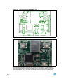
The top silk-screen view and photo of the full board, respectively, are shown in Figure 2 and
Figure 3.
5/33
Evaluation kit description
Figure 2.
Top silk-screen of the EK302DL kit
Figure 3.
Board photograph
UM0313
Operation of the EK302DL Evaluation Kit requires the installation of a dedicated driver
which is included on the CD in the kit, together with a GUI interface which allows simple
interaction with the sensor. The steps required for driver and software installation are
described in the following section.
6/33
UM0313
2
EK302DL GUI installation
EK302DL GUI installation
The installation of the Graphical User Interface (GUI) for the EK302DL requires two steps:
2.1
1.
installation on the PC of the software delivered with the evaluation kit.
2.
installation of the Virtual COM driver needed to use the evaluation kit board.
PC system requirements
Both the hardware and software that compose the EK302DL Evaluation Kit have been
designed to operate with Microsoft® Windows XP.
2.2
Software installation
To install the software distributed with the EK302DL Evaluation Kit:
1.
insert the mini CD into the CD-ROM drive;
2.
if the “Autorun” screen does not appear, click on Start > Run, then enter
“D:\Autorun.exe” and click OK. “D” represents the letter of your CD-ROM drive;
3.
click on “Evaluation Kit SW Installation” from the “EK302DL Evaluation Kit” page;
4.
follow the on screen instructions (Figure 4).
Figure 4.
2.3
Software installation
Hardware installation
To install the virtual COM driver, insert the evaluation kit board into a free USB port. The
“Notify” icon should appear as in Figure 5.
7/33
EK302DL GUI installation
Figure 5.
UM0313
Notify icon
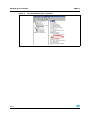
If the “Hardware Update Wizard” window appears (Figure 7), follow the instructions on the
screen. Otherwise, the installation can be performed by following the instructions indicated
in Figure 6 and Figure 7.
Figure 6.
Driver installation using the device manager
Right click on My Computer
Right click on “ST MEMS UNIT” and choose Update driver
1
2
8/33
UM0313
EK302DL GUI installation
Figure 7.
USB driver installation using the Hardware Update Wizard
3
4
6
5
7
Once the installation is complete, a COM port number will be assigned to the ST Virtual
COM driver (Figure 8). This number should be retained as it will be required to run the
EK302DL Evaluation Software GUI. For additional details, see section 3.1.
9/33
EK302DL GUI installation
Figure 8.
10/33
Virtual COM driver port assignment
UM0313
UM0313
3
Graphical User Interface
Graphical User Interface
To execute the EK302DL Evaluation Software GUI:
1.
click on Start > All Programs;
2.
select EK302DL > Executables;
3.
launch the program “EK302DL Ver.1.3”.
The GUI main window will appear as shown in Figure 9. The functions of the four main
sections of the window are described below:
●
Connection panel (ref 1) - Connects/disconnects the board and starts acquisition via
the Start/Stop buttons.
●
“Save” box (ref 2) - Allows the user to save the data to a specified file.
●
Tab Menu (ref 3) - Used to toggle between the different functions of the evaluation kit.
Figure 9.
Graphical User Interface: main window
ref 3
ref 1
ref 2
11/33
Graphical User Interface
3.1
UM0313
Connecting to the Virtual COM port
Before using the functions of the evaluation kit software it is necessary to open the
connection with the EK302DL board. This is achieved through the following procedure:
1.
connect the EK302DL to the desired USB port;
2.
in the “Select COM” drop-down menu (Figure 9 ref 1), choose the Virtual COM number
to which the board has been mapped. For additional information on how to obtain this
number, see section 2.3;
3.
open the connection by clicking on “Connect” (Figure 9 ref 1). When this procedure is
complete, the general purpose LED on the board will switch from red to green.
At this point the user can acquire, plot and save the acceleration data measured by the
sensor and access the content of the registers embedded in the device.
The following sections provide details regarding the functions of the tabs in Figure 9, ref 3.
3.2
“Options” tab
The Options tab allows the user to control the following parameters:
12/33
●
Full Scale (FS) - Sets the maximum acceleration value measurable by the device. It is
possible to select either 2g or 8g (Figure 10, ref 1).
●
Data Rate (DR) - In this box the rate at which each acceleration sample is produced
can be selected. The possible values are 100 Hz or 400 Hz (Figure 10, ref 2).
●
Tri-State (TS) - Permits switching the SPI lines of the ST7-USB microcontroller
mounted on the evaluation kit between 3-state (i.e. high-impedance) and normal mode
(Figure 10, ref 3). This function makes it possible to isolate the sensor mounted on the
board from the microprocessor, in case any external control (from a different
microcontroller mounted on a separate user board) is needed.
●
High-Pass Filter (HP) - This control activates the High-Pass Filter on the device and
selects the cut-off frequency (Figure 10, ref 4).
●
Interrupt on Pad IntX - Allows the selection of the type of signal to be sent out on Int1
and Int2 Pad (Figure 10, ref 5).
UM0313
Graphical User Interface
Figure 10. Options tab
ref 1
ref 2
ref 3
ref 4
ref 5
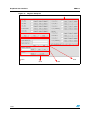
3.3
“Register Setup” tab
The Register Setup tab shown in Figure 11 allows read/write access to the content of the
registers embedded in the LIS302DL MEMS sensor mounted on the evaluation kit. The tab
is divided into five sections:
●
“General” (ref 1) - Provides access to the registers which control the main settings of
the device. This section contains the control registers (CTRL_REG1, CTRL_REG2 and
CTRL_REG3) and the registers that control the generation of inertial interrupt signals.
It is possible to read and write the contents of each register. To restore the default value
for a given register, press the “Default” button.
●
“All Registers” (ref 2) - Permits the user to read, write and recall the default content for
all the registers shown in ref 1 with a single click on the read/write/default button.
●
“Direct Communication” (ref 3) - Provides access to any register in the device. To read
a generic register, insert the address in the “Register Address” textbox, then click on
the “Read” button. The retrieved content of the register will be displayed in the
“Register Value” field. As with writing to a register, the user must specify the address
and the data to be written inside the fields marked “Register Address” and “Register
Value”, respectively, and then press the “Write” button.
●
“Load/Save Configuration” (ref 4) - Lets the user save/load a specific configuration
to/from a file.
●
“Parameters” (ref 5) - Allows the user to save the register configuration to a text file,
which includes a detailed description of the resulting configuration for each register.
13/33
Graphical User Interface
UM0313
Figure 11. Register Setup tab
ref 1
ref 3
ref 2
ref 5
14/33
ref 4
UM0313
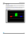
3.4
Graphical User Interface
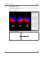
“Bars” tab
The Bars tab (Figure 12) displays the acceleration data measured by the LIS302DL sensor
in bar chart format. The accelerations along the X, Y and Z axes correspond respectively to
the RED, GREEN and BLUE bars.
The length of each bar is determined by the amplitude of the acceleration signal measured
along the related axis. The full scale of the graph depends on the FS bit of CTRL_REG1 that
may be changed through both the Option (Figure 10) and the Register Setup tabs
(Figure 11).
Figure 12. Bars tab
15/33
Graphical User Interface
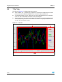
3.5
UM0313
“Plot” tab
The Plot tab (Figure 13) is divided into three sections:
●
“Main window” (ref 1) - Shows the sequence of acceleration samples that have been
measured by the LIS302DL MEMS sensor mounted on the evaluation kit.
●
“Visualization options” (ref 2) - Allows the user to enable/disable the trace related to
each axis and to show/hide the marker on the plot diagram.
●
“Zoom options” (ref 3) - Permits enlargement of the plot in the horizontal (Time) and
vertical (Amplitude) directions and to move the center of the plot upward/downward
with the “Up” and “Down” buttons.
Figure 13. Plot tab
ref 2
ref 1
ref 3
16/33
UM0313
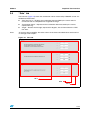
3.6
Graphical User Interface
“Data” tab
The Data tab (Figure 14) shows the acceleration values measured by LIS302DL sensor. It is
divided into three boxes:
Note:
●
“ADC Out” (ref 1) - Displays the acceleration data provided by the sensor after its
conversion from 2’s complement to magnitude and sign.
●
“Acceleration Value” - Represents the acceleration data measured by the sensor,
expressed in mg.
●
“Angle” - Returns the tilt angle, expressed in degrees, that is inferred from the “ADC
Out” data.
To increase data readability, the values shown in the boxes described above are based on
an average of 50 samples.
Figure 14. Data tab
ref 1
ref 2
ref 3
17/33
Graphical User Interface
3.7
UM0313
“Inclinometer” tab
The Inclinometer tab (Figure 15) represents the acceleration data measured by the sensor
in the form of an artificial horizon.
Figure 15. Inclinometer tab
Figure 16. Axis Inclination
+90°
0°
x,y,z
-90°
18/33
horizontal plane
UM0313
3.8
Graphical User Interface
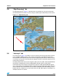
“Map Browsing” tab
The Map Browsing tab (Figure 17) demonstrates the possibility of using the acceleration
data obtained from the sensor to scroll a map (or another type of document) on the screen.
Figure 17. Map Browsing tab
1
2
3.9
“Interrupt” tab
The Interrupt tab (Figure 18) provides a tool for evaluating the interrupt generation features
of the LIS302DL MEMS sensor. In this section of the GUI it is possible to configure the
characteristics of the inertial events that must be recognized by the device and to visualize,
in real-time, the level of the two interrupt lines together with the acceleration signals that are
measured by the device.
The GUI provides direct access to the registers (INT_CFG, INT_SRC, THS and DURATION)
that allow the configuration of the two independent interrupt sources of the device.
Conversion boxes are located on the right most side of the THS and DURATION registers
(ref 1). These boxes are intended to show, respectively, the threshold value expressed in mg
and the duration value converted in msec for better readability and understanding. On the
bottom side of the window (ref 2), the content of the FF_WU_SRC register is reported for an
immediate check of its content.
19/33
Graphical User Interface
UM0313
Finally, two buttons are provided for each interrupt line to set the suggested default values
for free-fall and wake-up detection. Those buttons are marked “Set FreeFall Default” (ref 3)
and “Set Wake Up Default”, respectively (ref 4).
Figure 18. Interrupt tab
ref 1
ref 2
ref 3
20/33
ref 4
UM0313
3.10
Graphical User Interface
“Click” tab
The Click tab (Figure 19) is a tool to evaluate the “Click Recognition” function of the
LIS302DL MEMS sensor. This function allows the recognition of a “Single Click” and a
“Double Click” event and provides an interrupt when the event occurs.
Acceleration data (top section) and recognized click events (bottom section) are plotted in
real-time for each axis. On the bottom the level of the Interrupt is plotted . This tab provides
direct access to the registers (TAP_THSY_X, TAP_THSZ, TAP_DURATION,
TAP_LATENCY, TAP_WINDOW), allowing the user to fully configure the “Click Recognition”
function and the external interrupt lines.
Two buttons allow the user to set standard values for single and double click.
Figure 19. Click tab
21/33
Data acquisition quick start
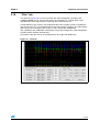
3.11
UM0313
“FFT” tab
The FFT tab (Figure 20) shows the FFT of the acceleration signals acquired by the sensor.
The spectral data are updated every sample and are calculated on a 64-sample moving
window.
Figure 20. FFT tab
4
Data acquisition quick start
This section describes the basic steps that must be performed to acquire the acceleration
data from the EK302DL:
22/33
1.
connect the EK302DL to the USB port;
2.
start the EK302DL GUI;
3.
select the Virtual COM port and click on the “Connect” button (Figure 9, ref 1);
4.
select the destination file to which the acceleration data must be saved by clicking
“Browse” (Figure 9, ref 2) in Save section (optional);
5.
use the Tab Menu to display the desired function (optional);
6.
click on the “Start” button to activate the sensor data collection and screen plotting
functions;
7.
click on the “Start saving” button to activate the sensor data saving to file;
8.
click on the “Stop saving” button to stop the sensor data saving;
UM0313
EK Lite
9.
click on the ”Stop” button to stop the sensor data collection and screen plotting
functions;
10. to close the application, click on “Disconnect” and then click on “Exit”.
5
EK Lite
The mini CD included with the EK302DL also contains a lite version of the previous GUI
together with its source code. The source code can be found in the directory:
($Home)\STM\EK302DL\EK302DL_lite, where ($Home) is the directory in which the
software that came with the evaluation kit was installed (C:\Program Files by default).
The purpose of the lite version is to provide the user a base for the development of a
customized application.
The lite version of the evaluation kit is started by launching the EK302DL Lite executable file
located in the EK302DL > Executables folder.
An example of the GUI of the EK lite application is shown in Figure 21.
Figure 21. EK302DL Lite GUI
Follow these instructions to use the software:
1.
connect the EK302DL to the USB port;
2.
start the EK302DL Lite GUI;
3.
select the Virtual COM port and click on the “Connect” button (Figure 9, ref 1);
4.
select the destination file to which the acceleration data must be saved by clicking
“Browse” (Figure 9, ref 2) in Save section (optional);
5.
use the Tab Menu to display the desired function (optional);
6.
click on the “Start” button to activate the sensor data collection and screen plotting
functions;
23/33
MEMS pointer
UM0313
7.
click on the “Start saving” button to activate the sensor data saving to file;
8.
click on the “Stop saving” button to stop the sensor data saving;
9.
click on the ”Stop” button to stop the sensor data collection and screen plotting
functions;
10. to close the application, click on “Disconnect” and then click on “Exit”
The GUI also gives read/write access to the registers embedded in the LIS302DL device
and allows a single read of the acceleration data measured by sensor.
6
MEMS pointer
This section describes how to use a simple pointer application, which utilizes acceleration
data provided by the LIS302DL MEMS 3-axis linear accelerometer to control the position of
a pointer on the screen of the PC. The software provided with the kit allows the EK302DL
Evaluation Kit board to be used as an inertial mouse, where the tilt of the board is translated into
movement of the pointer. The board also emulates the left and right buttons of the mouse.
6.1
GUI description
The GUI window (see Figure 22) is divided into two sections. The top section contains the
main controls to open the connection to the evaluation kit and to start/stop the data
acquisition. The bottom section contains the pointer application controls.
Figure 22. MEMS Pointer Demo
24/33
UM0313
6.1.1
MEMS pointer
Right side: main controls
The buttons on the right side of the GUI and their related functions are described below:
6.1.2
●
Connection control - Selects the COM port on which the EK board is connected.
●
Acquisition control - Starts and stops acquisition.
●
Exit - Exits the MEMS Pointer Demo application.
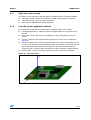
Left side: pointer application controls
The controls on the left side of the GUI and their related functions are as follows:
●
Left button/right buttons - Indicates when the left/right button on the evaluation kit is
pressed.
●
X/Y-position - Shows the current x/y coordinates of the mouse pointer on the PC
screen.
●
X/Y-deg - Shows the tilt of the evaluation kit along the X and Y axes as depicted in
Figure 23.
●
Tilt control - Allows the user to select the direction of the vertical displacement on the
screen vs. the direction in which the board is tilted. For example, by selecting “Up” the
pointer will move upward when the evaluation kit is tilted forward. Conversely, by
selecting “Down” the pointer will move downwards when the board is tilted backward.
●
Pointer speed - Sets the sensitivity of the pointer to the inclination of the board.
Figure 23. Axis orientation
25/33
Supported commands
7
UM0313
Supported commands
The microcontroller mounted on the EK302DL board is equipped with dedicated firmware
which supports a set of commands that allow the control of the 3-axis digital output MEMS
sensor and permit the aquisition of the measured acceleration data. The firmware also
handles the communication between the EK board and the PC through the USB bus. These
features allow users to easily write their own applications to exploit the capabilities of the
accelerometer.
This section describes the commands that are supported by the firmware loaded in the
microcontroller of the EK302DL Evaluation Kit.
7.1
Getting started
Before using the commands supported by the firmware, the following procedure must be
performed:
1.
connect the EK302DL to the USB port;
2.
launch an application which allows the sending of commands through the Virtual serial
port. The remainder of this document will assume the use of the Microsoft© Hyper
Terminal program integrated in the Windows XP operating system;
3.
create a new connection, enter a name (ex. “EK302DL”), and click “OK”;
4.
in the “Connect Using” field, select the Virtual COM port to which the USB port has
been mapped, and click “OK”;
5.
in Port Settings, set Bits per second to 115200, Data bits to 8, Parity to None, Stop bits
to 1, and Flow control to None. Click “OK”;
6.
in the Hyper Terminal select Files > Properties > Settings and then click on the “ASCII
Setup” button;
7.
select “Send line ends with line feeds” and “Echo typed characters locally”;
8.
click the “OK” button to close the “ASCII Setup” window;
9.
click the “OK” button to close the “Properties” window.
Once this procedure has been completed the user can utilize the commands described in
the following sections by typing them into the Hyper Terminal window.
26/33
UM0313
7.2
Supported commands
Supported commands
The table below lists the commands supported by the EK302DL firmware:
Table 1.
Supported commands
Command
*start
*debug
Note:
Description
Starts continuous data acquisition
Returns the acceleration data in readable
text format
*stop
Stops data acquisition
*rAA
Register read
*wAADD
Register write
*bwAA<0:7><0|1>
Single bit write
Returned value
S T x y z I1 I2 s
x=XX y=YY z=ZZ
RAAhDDh
*Zon
Force 3-state
*Zoff
Exit from 3-state
*dev
Device name
LIS302DL
*ver
Firmware version
302DL 1.1
AA: register address
DD: data
S: service field
XX, YY, ZZ: Acceleration data returned for the X, Y and Z axes
I1, I2 : interrupt value on each axes.
7.2.1
Start command
The *start command initiates the continuous data acquisition. When this command is sent to
the board, it returns the acceleration data measured by the LIS302DL device. The
acceleration data are packed in a string composed of eight bytes: “s t X Y Z I1 I2 SD”. The
first two bytes are always “s” and “t” which correspond to the hexadecimal values {73 74},
while “X” “Y” “Z” represent, respectively, the acceleration data for the X, Y, Z axes.
“I1” and “I2” contain the values of FF_WU_SRC1 and FF_WU_SRC2, where each bit is a
specific interrupt.
The last byte “s” returns information about the switches mounted on the board. Specifically,
bit#1 and bit#0 of the "service data" correspond to the status of SW3 and SW2 on the
evaluation kit board, and they are set to 1 when the corresponding switch is pressed.
7.2.2
Debug command
The *debug command starts the continuous data acquisition in debug mode. When this
command is sent to the board it returns the acceleration data measured by the LIS302DL
device in readable text format. The values shown on the screen correspond to the content of
the output data registers and are shown as a hexadecimal number. A TAB is employed as a
separator between the different fields.
27/33
Supported commands
7.2.3
UM0313
Stop command
The *stop command interrupts any acquisition session that has been started with either the
*start or *debug commands.
7.2.4
Register read
The *rAA command allows the contents of the LIS302DL device registers in the evaluation
kit board to be read. AA, expressed as hexadecimal value and written in upper-case,
represents the address of the register to be read.
Once the read command is issued, the board will return RAAhDDh, where AA is the address
sent by the user and DD is the data present in the register.
For example, to read the CTRL_REG1 the user would issue the command *r20, which
returns R20hC7h.
7.2.5
Register write
The *wAADD command permits writing to the contents of the LIS302DL device registers in
the evaluation kit board. AA and DD, expressed as hexadecimal values and written in uppercase, represent respectively the address of the register and the data to be written. To write
0xC7 to the CTRL_REG1, for example, the user would issue the command *w20C7.
7.2.6
Single bit write
Using this command it is possible to set/reset a single bit in a given register. The command
*bwAA<0:7><0|1> requires the user to specify the address AA of the register in which to
change the bit, with AA expressed as a hexadecimal value and written in lower-case,
followed by the position of the bit to be changed, an integer between 0 and 7, and the value,
either 0 or 1, to be associated to the specified bit.
For example, to set to 1 the FS bit within the CTRL_REG2, the user would issue the
command *bw2171.
7.2.7
Zon and Zoff
The *Zon and *Zoff commands are employed respectively to put into 3-state (i.e. highimpedance) and to exit (i.e. normal mode) the SPI lines of the ST7-USB microcontroller
mounted on the evaluation kit. These commands allow the isolation of the sensor from the
microprocessor in the event that an external control (from a different microcontroller
mounted on a separate board) is needed.
By default, when the kit is first turned on, the SPI lines are in 3-state mode and the user is
required to send the command *Zoff to allow the communication between the sensor and
the microcontroller.
7.2.8
Device name
The *dev command retrieves the name of the device mounted on the evaluation kit
connected to the PC. For the EK302DL, the returned value is “LIS302DL”.
28/33
UM0313
7.2.9
Supported commands
Firmware version
The *ver command queries the evaluation kit and returns the version of the firmware loaded
in the microprocessor.
7.3
Quick start
This section shows the basic sequence of commands to start a data communication session
and retrieve the acceleration data from the evaluation kit:
1.
connect the EK302DL to the USB port;
2.
start Microsoft© Hyper Terminal and configure it as described in section 7.1;
3.
inside the Hyper Terminal window, enter the command *Zoff to enable the control of the
SPI line from the ST7-USB microcontroller;
4.
send the *debug command to get the acceleration data measured from the sensor;
5.
send *stop to end the continuous acquisition and visualization.
29/33
USB_B
C8
47n
R6
1K5
+ C10
10u
220n
Rled
Gled
Vddf
+
C9
C1
10u
VCC
R7
10K
1
2
3
4
5
6
7
8
9
10
11
12
13
14
15
16
+
UV ss
UDM
UDP
UV cc
UV dd
Vddf
Vssf
PE5
PE6
PE7
PB0
PB1
PB2
PB3
PB4
PB5
C4
C2
100n 4u7
oscout
osci n
1
V+
2
DM
3
DP
4
GND
C5
100n
SW2
iccdata
icccl k
SW3
cs_pad
R8
10K
C3
4u7
PWM0
AIN6
AIN5
AIN4
AIN3
AIN2
OCMP2
OCMP1
PD3
PD2
PD1
PD0
PC7
PC6
PC5
PC4
48
47
46
45
44
43
42
41
40
39
38
37
36
35
34
33
+
VCC
CS1
C6
100n
U2
ST7265X_TQFP64
Cosc1
33p
osci n
Gled
D4
Rled
R2
100R
Vddf
12MHz
Yoscm1
R3
100R
J3
SPI
Cosc2
33p
oscout
TP1
VCC
Vddf
ICP
1
3
5
7
9
J2
6
5
4
3
2
1
2
4
6
8
10
VDD
GND
Test_SE
HV
GND_IO
Vdd_IO
sck
14
SCL
CS
J1
nRESET
iccsel
64
63
62
61
60
59
58
57
56
55
54
53
52
51
50
49
OSCOUT
OSCIN
V ss2
V ssa
V dda
V dd2
ICCDATA
ICCCL K
USBEN
A IN1
A IN0
SDA
SCL
RESET
V pp/ICCSEL
PWM1
PB6
PB7
PA 0
PA 1
PA 2
PA 3
PA 4
PA 5
PA 6
PA 7
SS
MISO
MOSI
SCK
V dd1
V ss1
INT1
INT2
R1
180R
INT2
CS1
sck
mi so
mosi
INT1
cs_pad
7
6
5
4
3
2
1
17
18
19
20
21
22
23
24
25
26
27
28
29
30
31
32
V ddf
miso
mosi
sck
G
30/33
7
iccdata
icccl k
nRESET
iccsel
INT2
INT1
8
miso
mosi
9
10
11
12
13
Riccsel1
10K
Int1
Int2
TESTEN
Reserved
SDO
SDA
U1
LIS302DL
SW1
NReset
R5
100R
C7
100n
R4
100R
D3
D2
8
cs_pad
R
D1
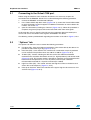
Schematic diagram
UM0313
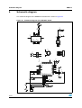
Schematic diagram
The schematic diagram of the EK302DL Evaluation Kit is shown in Figure 24.
Figure 24. Schematic diagram of the EK302DL board
UM0313
9
Bill of materials
Bill of materials
The bill of materials for the EK302DL Evaluation Kit is provided in Table 2.
Table 2.
Bill of materials
Designator
Description
Comment
Footprint
C1
Capacitor
10 µF
C1206_POL
C2
Capacitor
4.7 µF
C1206_POL
C3
Capacitor
4.7 µF
C1206_POL
C4
Capacitor
100 nF
0805
C5
Capacitor
100 nF
0805
C6
Capacitor
100 nF
0805
C7
Capacitor
100 nF
0805
C8
Capacitor
47 nF
0805
C9
Capacitor
220 nF
0805
C10
Capacitor
10 µF
C1206_POL
Cosc1
Capacitor
33 pF
0805
Cosc2
Capacitor
33 pF
0805
D1
Led
SMD_LED red
SMD_LED
D2
Led
SMD_LED red
SMD_LED
D3
Led
SMD_LED green
SMD_LED
D4
Led
J1
USB connector
USB_B
USB_B
J2
Header, 5X2
ICP
HEADER_5X2_A
J3
Header, 7-Pin
SPI
HDR1X7
R1
Resistor
180 Ω
0805
R2
Resistor
100 Ω
0805
R3
Resistor
100 Ω
0805
R4
Resistor
100 Ω
0805
R5
Resistor
100 Ω
0805
R6
Resistor
1.5 kΩ
0805
R7
Resistor
10 kΩ
0805
R8
Resistor
10 kΩ
0805
Riccsel1
Resistor
10 kΩ
0805
SMD_LED_3C
SW1
Button
NReset
SMT_Button
SW2
Button
SMT_Button
SMT_Button
SW3
Button
SMT_Button
SMT_Button
LIS302DL
TLGA_5x3x1
ST72F651AR6T1E
TQFP64_10x10
12 MHz
OSC_SMD
U1
U2
Yoscm1
Crystal
31/33
Revision history
10
UM0313
Revision history
Table 3.
32/33
Revision history
Date
Revision
Changes
24-Nov-2006
1
Initial release.
08-Jun-2007
2
Click Tab description added.
UM0313
Please Read Carefully:
Information in this document is provided solely in connection with ST products. STMicroelectronics NV and its subsidiaries (“ST”) reserve the
right to make changes, corrections, modifications or improvements, to this document, and the products and services described herein at any
time, without notice.
All ST products are sold pursuant to ST’s terms and conditions of sale.
Purchasers are solely responsible for the choice, selection and use of the ST products and services described herein, and ST assumes no
liability whatsoever relating to the choice, selection or use of the ST products and services described herein.
No license, express or implied, by estoppel or otherwise, to any intellectual property rights is granted under this document. If any part of this
document refers to any third party products or services it shall not be deemed a license grant by ST for the use of such third party products
or services, or any intellectual property contained therein or considered as a warranty covering the use in any manner whatsoever of such
third party products or services or any intellectual property contained therein.
UNLESS OTHERWISE SET FORTH IN ST’S TERMS AND CONDITIONS OF SALE ST DISCLAIMS ANY EXPRESS OR IMPLIED
WARRANTY WITH RESPECT TO THE USE AND/OR SALE OF ST PRODUCTS INCLUDING WITHOUT LIMITATION IMPLIED
WARRANTIES OF MERCHANTABILITY, FITNESS FOR A PARTICULAR PURPOSE (AND THEIR EQUIVALENTS UNDER THE LAWS
OF ANY JURISDICTION), OR INFRINGEMENT OF ANY PATENT, COPYRIGHT OR OTHER INTELLECTUAL PROPERTY RIGHT.
UNLESS EXPRESSLY APPROVED IN WRITING BY AN AUTHORIZED ST REPRESENTATIVE, ST PRODUCTS ARE NOT
RECOMMENDED, AUTHORIZED OR WARRANTED FOR USE IN MILITARY, AIR CRAFT, SPACE, LIFE SAVING, OR LIFE SUSTAINING
APPLICATIONS, NOR IN PRODUCTS OR SYSTEMS WHERE FAILURE OR MALFUNCTION MAY RESULT IN PERSONAL INJURY,
DEATH, OR SEVERE PROPERTY OR ENVIRONMENTAL DAMAGE. ST PRODUCTS WHICH ARE NOT SPECIFIED AS "AUTOMOTIVE
GRADE" MAY ONLY BE USED IN AUTOMOTIVE APPLICATIONS AT USER’S OWN RISK.
Resale of ST products with provisions different from the statements and/or technical features set forth in this document shall immediately void
any warranty granted by ST for the ST product or service described herein and shall not create or extend in any manner whatsoever, any
liability of ST.
ST and the ST logo are trademarks or registered trademarks of ST in various countries.
Information in this document supersedes and replaces all information previously supplied.
The ST logo is a registered trademark of STMicroelectronics. All other names are the property of their respective owners.
© 2007 STMicroelectronics - All rights reserved
STMicroelectronics group of companies
Australia - Belgium - Brazil - Canada - China - Czech Republic - Finland - France - Germany - Hong Kong - India - Israel - Italy - Japan Malaysia - Malta - Morocco - Singapore - Spain - Sweden - Switzerland - United Kingdom - United States of America
www.st.com
33/33