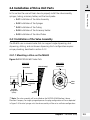
1
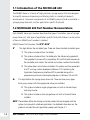
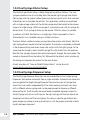
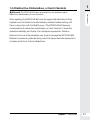
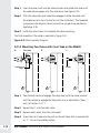
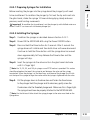
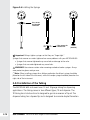
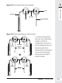
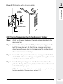
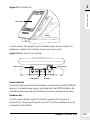
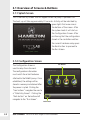
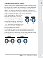
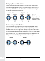
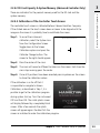
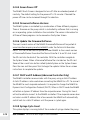
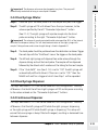
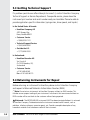
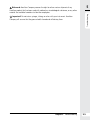
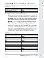
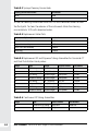
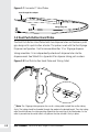
Step 6. Place the valve assembly onto the instrument as one assembled unit.
Step 7. Install two screws into each valve to secure the assembly to the
instrument.
2
Hardware Setup
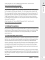
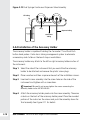
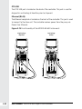
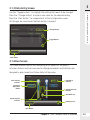
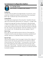
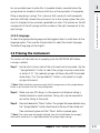
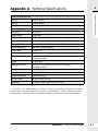
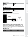
Step 5. Screw the cross tube into the valve port on the right valve marked by
an “R”. The valve shaft for the left and right valve should both point in
the same direction, so they can be slipped into the valve actuator. Do
not completely tighten the tubing.
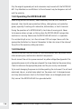
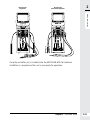
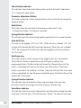
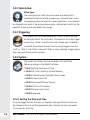
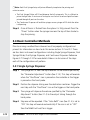
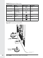
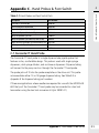
Step 8. Completely tighten the cross tube on both valves.
2.4.2 Installation of Syringes
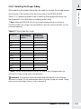
In this section the user will learn how to properly prepare and install the syringes
onto the MICROLAB 600.
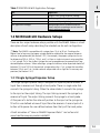
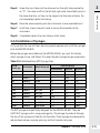
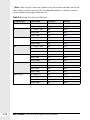
Before the syringes are installed on the MICROLAB 600, you must first decide
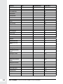
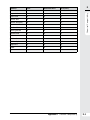
which syringes to use. Use Table 2-5 to select the best syringe for your application.
Table 2-5 BubbleFreePrime (BFP) Syringe Sizes
Flow Rate (µL/sec)
Syringe
Volume (µL)
Part Number
Optimal Range (µL)
Recommended
Minimum
Maximum
10
59000-05
1.0–10
5
0.003
6.5
25
59000-10
2.5–25
12.5
0.007
16.5
50
59000-15
5–50
25
0.014
33
100
59000-20
10–100
50
0.03
66.5
250
59000-25
25–250
125
0.07
166.5
500
59000-30
50–500
250
0.14
333
1,000
59000-35
100–1,000
500
0.3
665
2,500
59000-40
250–2,500
625
0.7
1,250
5,000
59000-45
500–5,000
1250
1.4
2,500
10,000
59000-50
1,000–10,000
2500
3
5,000
25,000
59000-55
2,500–25,000
3125
7
6,000
50,000
59000-60
5,000–50,000
3125
14
6,000
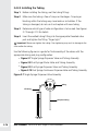
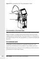
The BFP Syringes are specifically designed for the MICROLAB 600. They are
GASTIGHT syringes with a unique plunger tip. The plunger tip extends through
the top of the syringe and slightly into the valve. These syringes are designed to
reduce dead volume, improve priming, and limit sample carry-over.
Chapter 2 Hardware Setup
2-11