1
35(0,(56;
),5($/$50
&21752/3$1(/
86(50$18$/
0$,17(1$1&(*8,'(
/2*%22.
.
PREMIER SX USER MANUAL, MAINTENANCE GUIDE & LOG BOOK
CONTENTS
1. Safety ……………………………………………………………………………………
Important information regarding the safe use of this Fire Alarm Panel
3
2. Fire Alarm Systems ……………………………………………………………………
How fire alarm systems operate and a general overview of the key features
3
3. User Responsibilities …………………………………………………………………
General guidelines on what the User is expected to do, including daily, weekly,
quarterly & annual checks
4
4. Panel Layout/Accessing the Controls ……………………………………………..
A summary of the controls and indicators available on the Fire Alarm Panel
4.1
GENERAL CONTROLS
4.2
ACCESSED CONTROLS
4.3
WHAT THE INDICATORS MEAN
4.4
TESTING THE INDICATOR LIGHTS
5
5. Fire Conditions …………………………………………………………………………
5.1
HOW AN ALARM IS INDICATED
5.2
SILENCING THE ALARM SOUNDERS
5.3
NEW ZONE IN ALARM
5.4
MANUALLY ACTIVATING THE ALARM SOUNDERS
5.5
RESETTING THE PANEL
7
6. Fault Conditions ……………………………………………………………………….
6.1
DIFFERENT TYPES OF FAULT
6.2
IN THE EVENT OF A FAULT CONDITION
8
7. Disablements
7.1
7.2
7.3
10
…………………………………..………………………………………
REASONS FOR DISABLING CERTAIN PARTS OF A FIRE ALARM SYSTEM
TO DISABLE A ZONE AND/OR EXTERNAL SOUNDER
TO ENABLE A ZONE AND/OR EXTERNAL SOUNDER
8. Notes on Delays ……………………………………………………………………….
11
8.1
WHAT IS A DELAY
8.2
DELAY OPTIONS
8.3
DELAY INDICATION
8.4
WHAT HAPPENS IF THERE IS A FIRE ALARM CONDITION ON A DELAYED
PANEL
8.5
HOW TO OVERRIDE A DELAY IN THE EVENT OF A TRUE ALARM CONDITION
8.6
HOW TO RESET THE SYSTEM IN THE EVENT OF A FALSE ALARM
8.7
HOW TO TURN OFF THE SOUNDER DELAY
9. System Set-up Data Chart …………………………………………………………...
Details of how the System has been set-up
12
10. Log Book ………………………………………………………………………………..
A place for you to record details of events such as fires, false alarms, call
outs, etc.
13
11 Commissioning the system …………………………………………………………
15
11.1 Installation and Commissioning Certificate ………………………………………
15
Approved Document No: GLT.MAN-102T
Issue: 1.1
Authorised: GH
Date: 06/11/02
PAGE 2
PREMIER SX USER MANUAL, MAINTENANCE GUIDE & LOG BOOK
1. SAFETY
This Fire Alarm Panel is safe to operate provided it has been installed in compliance with the Manufacturers
instructions and used in accordance with the Manual.
Do not open the Fire Alarm Panel enclosure . There is no need to open the enclosure except to carry out
commissioning, maintenance and remedial work. This work must only be carried out by competent service
personnel who are fully conversant with the contents of the separate engineering manual for this product.
If the enclosure is damaged in any way, expert advice should be sought regarding its repair.
Regular Servicing of the Fire Alarm System is highly recommended, preferably on a continuous maintenance
contract and by a competent organisation. A fully-itemised report of the installation should be obtained at least
annually.
&(
(XURSHDQ 8QLR
8QLRQQ 'LUHFWLYHV &RQIRUPDQFH 6WDWHPHQW
This product has been manufactured in conformance with the requirements of all
applicable EU Council Directives. The Declaration of Conformance for this
product is located at the following Address: GLT Exports Ltd, 72-78 Morfa Road,
Hafod, Swansea, SA1 2EN, United Kingdom
2. FIRE ALARM SYSTEMS – AN OVERVIEW
The primary purpose of a Fire Alarm System is to provide an early warning of a fire so that people and animals
can be evacuated and action taken to stop the fire as soon as possible – all according to a predetermined plan.
Alarms may be raised automatically by Smoke or Heat Detectors, or manually be a person operating a Manual
Call Point.
To ensure an Alarm is dealt with in an orderly manner, it is important to know where the alarm is coming from.
To do this, Fire Alarm systems are usually split into Zones, each covering a different area of a building.
When an Alarm has been raised, the Fire Alarm Panel responds by indicating the Zone in which the Alarm has
occurred and activating all relevant Sounders, Bells and other Alarm Outputs to provide a warning of the fire.
•
•
A Remote Output: normally used to transmit an Alarm condition to an off-site permanently manned
monitoring centre. On receipt of the Alarm signal, the Centre notifies the local Fire Brigade of the Fire
Condition.
An Auxiliary Output: normally used to trigger local fire fighting equipment such as magnetic door
release systems (to automatically close fire doors), plant shutdown systems (to automatically switch off
potentially hazardous machines), sprinkler systems, etc.
Fault Monitoring
For obvious reasons the reliability of the Fire Alarm System is paramount. To this end, the fire alarm panel
continuously monitors all connections between Detectors, Manual Call Points and Sounders and checks its own
power supply and back-up batteries for faults.
If a fault is detected anywhere on the System, the Panel responds by illuminating one or more of the fault
light(s) located on the front of its enclosure and by sounding its internal fault buzzer. The Panel’s Fault Output
is also activates, sending notification of the fault (if connected) to a remote manned monitoring centre or other
electronic equipment, as required.
Delays
A Fire Alarm System can be prone to conditions that lead to frequent and unavoidable false alarms, a common
example being a waiting room filled with cigarette smoke. In areas such as these, it is acceptable to apply a
Delay to the Panel, which postpones the activation of the Alarm Sounders for a predetermined time. This Delay
period gives a responsible person time to investigate the cause of the Alarm and override the Delay if the cause
is found to be a true fire hazard to reset the Panel if the cause is found to be a False Alarm.
Disablements
In abnormal conditions, certain parts of the Fire Alarm System can be temporarily turned off (disabled) to suit
prevailing conditions. For example, if there is a risk of a false alarm occurring in a zone from vehicle exhaust
smoke in a loading bay, it is possible to disable that Zone during the risk period, then enable it again
afterwards. Another example of the disablement of outputs is during a routine test, or temporary fault.
Power Supply Equipment- General Description.
The NPSX FACP has an integral linear power supply capable of supplying 1.2 amps in total. It contains a current
limited output for charging sealed lead acid batteries (7 Ah maximum). The PSE is monitored for main supply
failure, the battery not taking a charge and low battery voltage. If the battery voltage drops below approximately
20VDC (a fault condition), the battery charging current will be turned off , thus stopping charging. This PSE is
only capable of supplying power to the CIE, and is not designed for any other use.
Approved Document No: GLT.MAN-102T
Issue: 1.1
Authorised: GH
Date: 06/11/02
PAGE 3
PREMIER SX USER MANUAL, MAINTENANCE GUIDE & LOG BOOK
3. USER RESPONSIBILITIES & MAINTAINENCE OF THE FIRE ALARM
SYSTEM, INCLUDING THE FACP & ITS INTEGRAL PSE
EN54: Pt 1: 1988 is the British Standard Code for the Design, Installation and Servicing of Fire Detection and
Alarm Systems for Commercial Buildings. Section Four of the Code (User Responsibilities) states that the
owner or person having control of the premises should appoint a responsible person to oversee the effective
operation of the Fire Alarm System (Clause 28.1).
Highlighted below is a summary of the main functions the Responsible ‘Person is expected to carry out. Please
note, this summary does not replace Section Four of EN54: Pt 1: 1988 (copies of which are available at your
local reference library or from the BSI). It is hoped this summary will help the User gain a greater
understanding of his or her responsibilities with regard to the safe upkeep of the Fire Alarm System. The
bracketed number (xx) identifies the EN54: Pt 1: 1988 clauses to which the summary refers.
The responsible person must
1.
Ensure that all necessary work is carried out to guarantee the effective operation of the system, the
maintenance of records and the servicing of the system (28.1.1).
2. Devise procedures for dealing with fire alarms, faults, etc, for approval by the appropriate fire authority
before implementation (28.1.2).
3. Ensure all users of the system are trained in how to use the system properly and that all building
occupants are aware of the action(s) to be taken in the event of a fire situation (28.1.3)
4. Effectively communicate with building/security personnel to ensure that cleaning, maintenance or building
work does not interfere with the functioning and reliability of the system (28.1.4).
5. Ensure that the operation of the system is not hampered by obstacles, i.e. detectors and manual call points
should be completely unobstructed (28.1.5).
6. Ensure that records, drawings and instructions are updated on a regular basis and are readily available for
reference purposes (28.2.1).
7. Keep a Log Book to record all relevant details relating to the operation of the system (28.2.2).
8. Prevent false alarms by ensuring that:
a) staff and visitors to the building are aware that a fire alarm system is in operation (28.4.1.).
b) notices are displayed in all areas where detectors are sited (28.4.2).
c) contractors take appropriate precautions while working in protected areas (28.4.3).
d) precautions against dust and smoke are taken when temporary work is carried out in areas protected
by smoke detectors (28.4.4)
e) the system is properly reinstated after temporary work has been completed (28.4.5)
9. Ensure that the system is attended to regularly on a routine basis, i.e. testing procedure is carried out,
wiring check, etc (29.2).
10. Ensure that the system is correctly serviced at Daily, Weekly, Quarterly, Annual and Five Yearly intervals
(29.2) and also in special circumstances, i.e. following a fire, false alarm, etc, (29.3)
With the Premier SX Range of Fire Alarm Panels, we suggest the following tests are carried out as specified: Daily Inspection
• Check that the supply present indicator is lit.
• Report any faults to the designated site maintenance engineer.
Weekly Test (you may wish to temporarily disable the Remote Output during the following Tests)
• Carry out an Indicator lamp test to check all Zone lights shown and the buzzer sounds.
• Operate a manual call point or sensor to test the Fire Alarm.
• Check that the Alarm sounders operate.
• Reset the System by pressing the Silence/Activate Sounders button and Control Panel Reset button.
• Verify that no call points or smoke/heat detectors are obstructed in any way.
• Test a different zone each week using a different call point or detector so all are tested in rotation.
Quarterly Test (to be carried out by authorised service personnel only)
• Check all previous logbook entries and verify remedial action has been taken.
• Visually inspect the batteries and connections and check it is capable of supplying the alarm sounders.
• Operate a call point or detector in each zone to test the fire alarm as in the weekly test above.
Annual Test (to be carried out by authorised service personnel only)
As for the weekly and quarterly test but check every detector, call point, sounder and all auxiliary
•
equipment for correct operation.
Check Transformer output Voltage (32 VAC), Charger Voltage (27.8V off load, adjusted with VR1) &
•
Battery Voltage (25-27V)
Every Five Years (to be carried out by authorised service personnel only)
• Carry out a complete wiring check in accordance with the testing and inspection requirements of the
relevant National wiring regulations (in the UK this is the IEE Wiring Regulations). The Batteries should be
replaced because SLA batteries have a working life of 5 years.
Approved Document No: GLT.MAN-102T
Issue: 1.1
Authorised: GH
Date: 06/11/02
PAGE 4
PREMIER SX USER MANUAL, MAINTENANCE GUIDE & LOG BOOK
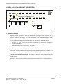
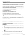
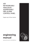
4. PANEL LAYOUT/ACCESSING THE CONTROLS
),5( =21(6
32 :(5
6833/< )/7
2 ))
&2 1 752/ 6
)/7
(1$ %/('
* (1 ),5 (
=21$/ )$8/7 ',6$%/(0(17 7(67
' (/
* (1 )$8/7
672 367$ 57
6<67(0 )/7
6,/(1&(
* (1 6&
5(6(7
)/7 72 1 (
6&52 // (1*,1((5
* (1 =2 1 ( 7(67
/(' 7(67
* (1 ' ,6$%/(0 (1 7
'(/$<
29(55,'(
Two levels of control are available to the User(s) of this Fire Alarm Panel.
4.1 GENERAL CONTROLS
When the Panel is in its Normal state, the indicator lights on the front of the enclosure give a
comprehensive overview of the System’s current status. Any Fire and Fault conditions are clearly
displayed, disablements highlighted. For detailed descriptions of what each indicator means, please
refer to the table on the opposite page.
The only functions that can be performed by the User when the Panel is in its Normal state are:
•
Overriding any Delays, which may have been programmed into the Panel by pressing the
Sounder Override button.
•
Putting the Panel into the Accessed state – see below.
4.2 ACCESSED CONTROL (AVAILABLE TO AUTHORISED USERS ONLY)
To avoid unauthorised changes to critical parts of the Fire Alarm System, controls such as silencing
the Sounders, resetting an Alarm condition and implementing Disablements are only accessible via a
secure method of entry which puts the panel into the Accessed state.
To put the Panel into the Accessed State: Turn the key to the control enable position (please note
the key should not be removed when in this position). To leave the Accessed state, turn the key back
to the off position.
Information on how to used the accessed control can be found on Pages 8 to 11 of this User Manual.
Approved Document No: GLT.MAN-102T
Issue: 1.1
Authorised: GH
Date: 06/11/02
PAGE 5
PREMIER SX USER MANUAL, MAINTENANCE GUIDE & LOG BOOK
4.3 WHAT THE INDICATORS MEAN
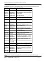
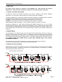
The table below summarises the various indicators available on the Fire Alarm Panel and what they mean in their
various states.
INDICATOR
Power
STATUS OF LIGHT
STEADY GREEN
WHAT THIS MEANS
The panel is supplied with power
GEN FLT
ONLY
STEADY YELLOW
Problem with keyswitch
GEN FLT &
SUPPLY FLT
STEADY YELLOW
FLASHING YELLOW
There is a problem with either the mains supply or
the battery backup
GEN FLT &
EARTH FLT
STEADY YELLOW
FLASHING YELLOW
There is a wiring problem. One of the cables is
touching the earth screen.
GEN FLT &
ZONAL FLT
STEADY YELLOW
FLASHING YELLOW
There is an open circuit fault in the wiring of the
zone indicated.
GEN FLT &
ZONAL FLT
GEN S/C
STEADY YELLOW
FLASHING YELLOW
FLASHING YELLOW
There is a short circuit fault in the wiring of the
zone indicated.
GEN FLT &
SND FLT
STEADY YELLOW
FLASHING YELLOW
There is an open circuit fault in the wiring of one
or both of the sounder circuits
GEN FLT &
SND FLT
GEN S/C
STEADY YELLOW
FLASHING YELLOW
FLASHING YELLOW
There is a short circuit fault in the wiring of one or
both of the sounder circuits
GEN FLT &
SYSTEM FLT
STEADY YELLOW
STEADY YELLOW
GEN FIRE
ONLY
STEADY RED
A processor fault has occurred. To reset, turn
keyswitch on then back off. If problem persists,
consult your dealer.
A manual evacuation has occurred.
The sounders will be active.
GEN FIRE &
ZONE FIRE
STEADY RED
STEADY RED
A fire has occurred in the zone indicated.
The sounders will be active.
GEN FIRE &
ZONE FIRE &
GEN DISABLE
& DEL
STEADY RED
STEADY RED
STEADY YELLOW
STEADY YELLOW
A fire has occurred in the zone indicated.
The sounders have a delay set, and will become
active after the programmed delay. To override
the display, press delay override.
GEN DISABLE FLASHING YELLOW
(FAST – 4 HZ)
The panel is ready for selecting disable or test
mode
GEN DISABLE FLASHING YELLOW
(SLOW – 0.5 HZ)
The panel is in SELECT DISABLEMENT MODE
GEN DISABLE FLASHING YELLOW
ZONE DISABLE
(SLOW – 0.5 HZ)
The user is scrolling through zones to select
which one to disable/or user has just enabled the
zone.
The indicated zone is disabled.
GEN DISABLE STEADY YELLOW
ZONE DISABLE
STEADY YELLOW
GEN DISABLE STEADY YELLOW
DEL
STEADY YELLOW
The Sounders are delayed by the amount set on
the rotary switch.
GEN TEST
ZONE DISABLE
The indicated zone is in Test Mode.
STEADY YELLOW
STEADY YELLOW
4.4 TESTING THE INDICATOR LIGHTS
To test the Panel’s indicator lights are working correctly, turn key switch to “Controls Enable” position then press
the LED test button. The panel’s internal buzzer will also sound when pressing the button to show it is working
correctly.
Approved Document No: GLT.MAN-102T
Issue: 1.1
Authorised: GH
Date: 06/11/02
PAGE 6
PREMIER SX USER MANUAL, MAINTENANCE GUIDE & LOG BOOK
5. FIRE CONDITIONS
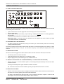
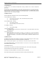
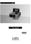
5.1 HOW AN ALARM IS INDICATED
),5( =21(6
32:(5
6833/< )/7
*(1),5(
672367$57
6<67(0 )/7
6,/(1&(
*(1',6$%/(0(17
'(/$<
29(55,'(
=21$/ )$8/7 ',6$%/(0(17 7(67
'(/
*(1)$8/7
)/7
*(16&
5(6(7
)/7 721(
6&52// (1*,1((5
*(1=21( 7(67
/(' 7(67
When the Fire Alarm Panel receives an Alarm trigger from a Detector or Manual Call Point located in a zone that
is not already in a fire state it will: -
•
•
•
Light the General Fire LED and appropriate Zone Fire LED(s) on the front of its enclosure
Sound Internal buzzer
Start the Alarm Sounder and Auxiliary output including, if enabled (provided there is no Delay applicable to
the sounders).
At this point the building’s fire management plan should be executed.
IMPORTANT NOTE: Zones which have been disabled cannot be triggered into Alarm Condition (see page
10 for further information on Disablements).
5.2 SILENCING THE ALARM SOUNDERS
•
The Alarm Sounders may be silenced by turning the control key to “Control Enable” position and momentarily
pressing the Start/Stop button.
The Alarm Sounders and the Panel’s Internal buzzer will cease to sound but the light(s) for the Zone(s) in Alarm
and the red General Fire light will stay lit. All other Alarm outputs (i.e. the Auxiliary Fire Outputs) will remain
asserted.
5.3 NEW ZONE IN ALARM
Should a new Zone be triggered into Alarm whilst the Alarm Sounders have been silenced, the Panel will: -
•
•
•
Automatically reactive the Alarm Sounders
Light appropriate Zone Fire LED(s) for any new Zone(s) in alarm
Keep the light(s) for the previous Zone(s) in fire, and General Fire lit.
5.4 MANUALLY ACTIVATING THE ALARM SOUNDERS (I.E. TO EVACUATE THE BUILDING).
•
With the control key in “Controls Enabled” position, momentarily pressing the Start/Stop will cause the Alarm
sounders to sound.
Pressing the Start/Stop button again will Silence the Alarm Sounders.
NB: If the Alarm Sounders have been disabled, pressing the Stop/Start button will have no effect.
5.5 RESETTING THE PANEL
•
After the cause of the alarm has been investigated and cleared and the Alarm Sounders have been silenced,
the Panel can be reset by pressing the Control Panel Reset button.
The Zone fire and General fire alarm lights will go out to indicate the process is complete. If there are still
alarm triggers on any Zone the Panel will go back into alarm as before.
Approved Document No: GLT.MAN-102T
Issue: 1.1
Authorised: GH
Date: 06/11/02
PAGE 7
PREMIER SX USER MANUAL, MAINTENANCE GUIDE & LOG BOOK
6. FAULT CONDITIONS
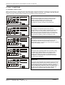
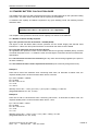
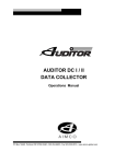
6.1 DIFFERENT TYPES OF FAULT
When a Fault occurs on a critical part of the Fire Alarm System, the Panel responds by activating its Internal buzzer and
illuminating the General Fault light and any other Fault light(s) relating to the Fault. The Panel’s Fault relay will also
activate. The types of Faults typically indicated at the Fire Alarm Panel are described below: ),5( =2 1(6
32 : (5
6 8 33/< ) /7
* (1 ) ,5 (
6 7236 7$5 7
6 < 67 (0 ) /7
6 ,/(1 & (
=2 1$ / )$ 8/7 ',6$ %/(0 (17 7(67
' (/
* (1 )$8 /7
* (1 6 &
5 (6 (7
6 & 5 2// (1*,1((5
* (1 =2 1 ( 7(6 7
* (1 ' ,6 $%/ (0 (1 7
'(/$<
29(55,'(
),5( =2 1(6
6 8 33/< ) /7
* (1 ) ,5 (
6 7236 7$5 7
6 ,/(1 & (
=2 1$ / )$ 8/7 ',6$ %/(0 (17 7(67
' (/
6 < 67 (0 ) /7
* (1 6 &
5 (6 (7
6 & 5 2// (1*,1((5
* (1 =2 1 ( 7(6 7
/(' 7(6 7
) /7 72 1 (
* (1 ' ,6 $%/ (0 (1 7
'(/$<
29(55,'(
),5( =2 1(6
32 : (5
6 8 33/< ) /7
* (1 ) ,5 (
6 7236 7$5 7
6 ,/(1 & (
=2 1$ / )$ 8/7 ',6$ %/(0 (17 7(67
' (/
6 < 67 (0 ) /7
The relevant Zone Fault light flashes when there is a
wiring problem on a Zone or detector has been removed from
its base. It should be noted that any alarms raised on the
fault zone(s) may not be recognised by the Fire Alarm Panel
until the Fault Conditions have been cleared. It can take up to
60 seconds from repairing a fault for the display to clear.
Short Circuit Fault
) /7
* (1 )$8 /7
Zone Fault
) /7
* (1 )$8 /7
The General Fault lights when there is a Fault on any part
of the Fire Alarm Systems It is usually lit in tandem with
at least one other fault light which conveys more
precise information on the type of Fault detected.
If this light is lit by itself, it indicates a keyswitch fault.
/(' 7(6 7
) /7 72 1 (
32 : (5
General Fault
) /7
* (1 6 &
5 (6 (7
6 & 5 2// (1*,1((5
* (1 =2 1 ( 7(6 7
If the Fault is a short circuit fault, then the S/C LED will be lit.
This GEN S/C LED will be lit for S/C faults on the zone
and sounder circuits. It can take up to 60 seconds from repairing
a fault for the display to clear.
/(' 7(6 7
) /7 72 1 (
* (1 ' ,6 $%/ (0 (1 7
'(/$<
29(55,'(
),5( =2 1(6
32 : (5
6 8 33/< ) /7
* (1 ) ,5 (
6 7236 7$5 7
6 < 67 (0 ) /7
6 ,/(1 & (
=2 1$ / )$ 8/7 ',6$ %/(0 (17 7(67
' (/
* (1 )$8 /7
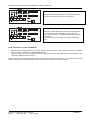
Power Supply Fault
) /7
* (1 6 &
5 (6 (7
6 & 5 2// (1*,1((5
* (1 =2 1 ( 7(6 7
/(' 7(6 7
) /7 72 1 (
* (1 ' ,6 $%/ (0 (1 7
'(/$<
29(55,'(
The Power supply Fault light flashes when the Mains supply
has failed or the standby batteries or its charger is faulty. If
the mains supply fails, the panel will only operate for the
standby period dictated by the size of the batteries fitted. If
the batteries or charger fails at the same time as the Mains,
the Panel will be inoperative.
),5( =2 1(6
32 : (5
6 8 33/< ) /7
* (1 ) ,5 (
6 7236 7$5 7
6 < 67 (0 ) /7
6 ,/(1 & (
) /7 72 1 (
System Fault
The System Fault LED lights when the Panel’s micro-processor
has Reset, typically after excessive electrical interference, or if
the contents of its memory have been corrupted. This fault can
only be cleared by turning the key switch from off position to
control enable position and then turn key to off position again. If
the fault re-occurs within two minutes, this is indicative of a
corrupt memory and expert advice should be sought.
=2 1$ / )$ 8/7 ',6$ %/(0 (17 7(67
' (/
* (1 )$8 /7
) /7
* (1 6 &
5 (6 (7
6 & 5 2// (1*,1((5
* (1 =2 1 ( 7(6 7
/(' 7(6 7
* (1 ' ,6 $%/ (0 (1 7
'(/$<
29(55,'(
Approved Document No: GLT.MAN-102T
Issue: 1.1
Authorised: GH
Date: 06/11/02
PAGE 8
PREMIER SX USER MANUAL, MAINTENANCE GUIDE & LOG BOOK
),5( =2 1(6
32 : (5
6 8 33/< ) /7
* (1 ) ,5 (
6 < 67 (0 ) /7
6 ,/(1 & (
* (1 6 &
5 (6 (7
6 & 5 2// (1*,1((5
* (1 =2 1 ( 7(6 7
* (1 ' ,6 $%/ (0 (1 7
'(/$<
29(55,'(
),5( =2 1(6
6 8 33/< ) /7
* (1 ) ,5 (
6 7236 7$5 7
6 ,/(1 & (
) /7 72 1 (
=2 1$ / )$ 8/7 ',6$ %/(0 (17 7(67
' (/
6 < 67 (0 ) /7
Sounder Fault
) /7
* (1 )$8 /7
The Earth Fault light flashes when the panel detects an earth
fault on the wiring to any part of the control panel.
/(' 7(6 7
) /7 72 1 (
32 : (5
Earth Fault
=2 1$ / )$ 8/7 ',6$ %/(0 (17 7(67
' (/
* (1 )$8 /7
6 7236 7$5 7
) /7
* (1 6 &
5 (6 (7
6 & 5 2// (1*,1((5
* (1 =2 1 ( 7(6 7
/(' 7(6 7
* (1 ' ,6 $%/ (0 (1 7
'(/$<
29(55,'(
The Sounder status light flashes when there is a wiring fault
on the Sounder Circuits. Depending on where the fault
has occurred, one or all of the Alarm Sounders may no longer
be operative.
If the fault is a short circuit fault, then the S/C LED will also
be lit.
6.2 IN THE EVENT OF A FAULT CONDITION
•
•
Mute the Panel’s Internal buzzer by pressing the Silence fault tone button. (The panel has to be in the Accessed
state to do this, i.e. keyswitch in controls enabled position.
Note the Fault(s) down in the Log Book at the back of this Manual and take appropriate action to correct it/them. See
User Responsibilities section on Page 5.
When a fault has been rectified the indicator light for that Fault is automatically turned off. If all Faults are cleared, the
General Fault light will go out and the Panel’s Internal Sounder will be silent (if not already muted).
Approved Document No: GLT.MAN-102T
Issue: 1.1
Authorised: GH
Date: 06/11/02
PAGE 9
PREMIER SX USER MANUAL, MAINTENANCE GUIDE & LOG BOOK
7. DISABLEMENTS
7.1 REASONS FOR DISABLING CERTAIN PARTS OF A FIRE ALARM SYSTEM.
Certain Fire Alarm Panels can be temporarily disabled (i.e. switch off) to suit prevailing conditions. For example, if there is
a risk of a False Alarm in a zone, say from vehicle exhaust smoke in a loading bay, it is possible for the user to disable
that zone during the risk period and then enable it again afterwards. During a disablement of a zone(s), no fire or fault
signal will be processed for that zone(s). A zone(s) in a non-alarm state can only be disabled, that is zones already in fire
cannot be disabled.
External sounders can also be disabled as could be required in certain conditions.
7.2 TO DISABLE A ZONE AND/OR EXTERNAL SOUNDERS.
1.
Turn control key to “Controls Enable” position;
2.
Press “Engineer” switch momentarily, this will cause General Disablement LED to flash (fast). This means the
panel is in disable/enable mode;
3.
Press scroll (No. 4) switch once and this will cause the General Disablement LED to flash (slow);
4.
Press scroll (No. 4) switch once again and this will cause Zone 1 Disablement LED to light steady;
5.
Pressing scroll (No. 4) switch will cause the zone disablement LED to toggle to zone 2 and so on;
),5( =2 1(6
32 : (5
6 8 33/< ) /7
* (1 ) ,5 (
6 7236 7$5 7
6 < 67 (0 ) /7
6 ,/(1 & (
) /7 72 1 (
=2 1$ / )$ 8/7 ',6$ %/(0 (17 7(67
' (/
* (1 )$8 /7
) /7
* (1 6 &
5 (6 (7
6 & 5 2// (1*,1((5
* (1 =2 1 ( 7(6 7
/(' 7(6 7
* (1 ' ,6 $%/ (0 (1 7
'(/$<
29(55,'(
6.
Select zone to be disabled. For example, if Zone 3 is selected and with Zone 3 disablement LED lit (steady) and
General Disablement LED flashing slow, pressing “Engineer” will cause General Disablement LED light to change
to steady. This means that zone 3 is now disabled;
7.
Switch controls key to off position, then both the disabled Zone Disablement LED and the General Disablement
LED will remain lit (steady.
7.3 TO ENABLE A ZONE AND/OR EXTERNAL SOUNDERS.
1.
Turn key to “Controls enable” position (since a zone is already disabled at this time, the General Disablement LED
with stay lit (steady);
2.
Press “Engineer” switch once and this will cause the General Disablement LED to flash (fast);
3.
Press scroll (No. 4) switch until the light is steady at the disabled zone;
4.
Press “Engineer” and this will cause the General Disablement LED to flash (slow);
5.
Turn control Key to “Off” position and this will turn off the General Disablement and Zone Disablement LEDs.
NOTES:
The option of disabling or enabling zones 3, 4, 5, 6, 7 and 8 is only available if these zones are present on the
panel
Approved Document No: GLT.MAN-102T
Issue: 1.1
Authorised: GH
Date: 06/11/02
PAGE 10
PREMIER SX USER MANUAL, MAINTENANCE GUIDE & LOG BOOK
8. NOTES ON DELAYS
8.1 WHAT IS A DELAY
A delay can be programmed into the fire alarm panel to postpone the activation of the Alarm Sounders for a
predetermined length of time. The Delay period gives a responsible person time to investigate the cause of an Alarm,
usually in areas which are prone to false alarm (such as waiting rooms filled with smoke) before the building is evacuated.
If the cause of the Alarm is found to be a true fire hazard, the Delay can be overridden and the Alarm Sounders activated
immediately. Alternatively, in the case of a false alarm, the Panel can be reset.
8.2 DELAY OPTIONS
All of the Zones of this Fire Alarm Panel can have a Delay applied to them to suit the requirements of the site. The same
Delay period applies to all Zones and is adjustable to a maximum of 9 minutes. The programming of the Delay must only
be carried out by competent service personnel who are advised to record relevant Delay Data on the System Set-up Data
Chart on Page 13 of this User Manual.
8.3 DELAY INDICATION
If a Delay has been programmed into the Panel, the General Disablement & DEL(AY) LEDs will be lit. When a zone
processes an alarm signal, the panel will indicate fire in the usual way, but the sounders will not be active until the delay
period has expired. To override this delay, press Delay Override Switch, which will cause the external sounders to
energise. If Delay is not programmed, the Delay Override Switch has no function.
8.4 WHAT HAPPENS WHEN THERE IS A FIRE ALARM CONDITION ON A DELAYED PANEL
Should an alarm occur on a Delayed Panel, the panel will: -
•
Light its General Fire and appropriate Fire Zone light(s)
•
Sound its Internal buzzer
•
Start the Delay countdown sequence
•
Wait until the end of the delay, then start the sounders.
8.5 HOW TO OVERRIDE A DELAY IN THE EVENT OF A TRUE FIRE ALARM CONDITION
If on investigation the cause of the Alarm is found to be a true fire hazard, pressing the Delay Override, will active the
Alarm Sounders and Outputs with immediate effect.
8.6 HOW TO RESET THE SYSTEM IN THE EVENT OF A FALSE ALARM
If, on investigation, the cause of the Alarm is found to be false, turn the Key switch to the “Controls Enabled” position and
press reset button.
8.7 HOW TO TURN OFF THE SOUNDER DELAY
There are two ways of turning off the sounder delay:1
Return the rotary switch to the 0 position.
2
Turn key to controls enabled position. Press engineer button (to select disablement mode). Press delay override
(the DEL LED will now go off to show that the delay is no longer active). Pressing Delay Override again will toggle the
delay back on.
Approved Document No: GLT.MAN-102T
Issue: 1.1
Authorised: GH
Date: 06/11/02
PAGE 11
PREMIER SX USER MANUAL, MAINTENANCE GUIDE & LOG BOOK
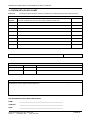
9. SYSTEM SET-UP DATA CHART
Important:
The sections below should be carefully completed by an authorised Engineer at system handover.
FIRE ZONE INFORMATION
ZONE
ZONE DESCRIPTION
NUMBER
A concise explanation of the rooms and areas contained in each zone
FITTED
Yes/No
Yes/No
Yes/No
Yes/No
Yes/No
Yes/No
Yes/No
Yes/No
LENGTH OF DELAY (1 TO 9 MINUTES) IF APPLICABLE
OUTPUT ROUTING INFORMATION
TYPE OF OUTPUT
CONNECTED
Auxiliary Output
Yes/No
Fault Output
WHAT HAPPENS WHEN ACTIVATED
Yes/No
ADDITIONAL INFORMATION
Any additional information the User needs to know about should be inserted into this box including details of the routing of
any additional outputs, details of inputs utilised, etc.
THE INFORMATION ABOVE WAS COMPLETED BY
NAME:
_________________________________________________________
COMPANY:
_________________________________________________________
DATE:
_________________________________________________________
Approved Document No: GLT.MAN-102T
Issue: 1.1
Authorised: GH
Date: 06/11/02
PAGE 12
PREMIER SX USER MANUAL, MAINTENANCE GUIDE & LOG BOOK
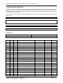
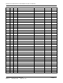
10. FIRE ALARM LOG BOOK
This section of the User Manual must be maintained by the responsible person(s) on site and must be available for
inspection at all times. Every “event” affecting the installation should be recorded including fire alarm conditions, failures,
tests, temporary disconnections, disablements, enablements, dates of installing engineers’ visits together with a note of
any outstanding work or conditions.
You are advised to make additional copies of the adjacent page so you have space for logging future events for when this
manual is full.
User:
Site Address:
Contract No:
Responsible Persons on Site:
FOR SERVICE
Normal House (Mon-Fri) Tel:
Manned Centre Tel:
DATE
TIME
ZONE
BRIEF DETAILS OF EVENT
Approved Document No: GLT.MAN-102T
Issue: 1.1
Authorised: GH
Date: 06/11/02
Outside Normal House Tel:
Manned Centre Code:
ACTION REQUIRED COMPLETED INITIALS
PAGE 13
PREMIER SX USER MANUAL, MAINTENANCE GUIDE & LOG BOOK
DATE
TIME
ZONE
BRIEF DETAILS OF EVENT
Approved Document No: GLT.MAN-102T
Issue: 1.1
Authorised: GH
Date: 06/11/02
ACTION REQUIRED
COMPLETED INITIALS
PAGE 14
PREMIER SX USER MANUAL, MAINTENANCE GUIDE & LOG BOOK
11 COMMISSIONING THE SYSTEM, INCLUDING P.S.E.
•
The commissioning of this fire alarm system should be performed by a qualified commissioning engineer.
•
The system layout drawing should be checked for accuracy & stored in a safe place, accessible to any fire officer.
•
The system set-up data chart (GLT.MAN-102, section 9) should be checked for accuracy.
•
The fire alarm log book contact details should be checked for completeness.
•
The system should be checked in accordance with EN54-1 26.2 for compliance with the recommendations.
•
The insulation of cables should be checked in accordance with EN54-1 26.3 for compliance.
•
The Earthing should be checked in accordance with EN54-1 26.4 for compliance.
•
The PSE mains feed from a 3A spur should be checked.
•
The PSE Charger voltage should be checked & adjusted if necessary (27.8V with batteries disconnected).
•
The battery voltage should be checked (should be between 24 & 27V)
•
The entire system should be checked in accordance with EN54-1 26.5 for satisfactory operation.
•
Any deviations from EN54-1 26.6 should be listed in the Certificate of Installation & Commissioning.
•
The Certificate of Installation & Commissioning should be completed, and the whole user manual passed to the
relevant person on site. (They should be given a brief training on the basic operation of the FACP)
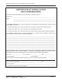
11.1 INSTALLATION & COMMISSIONING CERTIFICATE
Before this User Manual is handed over to the relevant person(s) on site, the following certificate must be completed by
the installation/commissioning engineer. The System Set-up Data Chart should also be completed on Page 13 as should
the relevant parts of the Log Book section on Page 14.
Approved Document No: GLT.MAN-102T
Issue: 1.1
Authorised: GH
Date: 06/11/02
PAGE 15
PREMIER SX USER MANUAL, MAINTENANCE GUIDE & LOG BOOK
&(57,),&$7(2),167$//$7,21
$1'&200,66,21,1*
This certificate confirms the installation and commissioning of a fire Alarm system at:
Protection area: _________________________________________________________________________________
Address:
_________________________________________________________________________________
_________________________________________________________________________________
_________________________________________________________________________________
In accordance with EN54: Part 1: 1998, sub clause 26.2, the installation has been inspected for compliance with the
recommendations of the code.
In accordance with EN54: Part 1: 1998, sub clause 26.3, the insulation of cables and wires has been tested.
In accordance with EN54: Part 1: 1998, sub clause 26.4, the earthing has been tested.
In accordance with EN54: Part 1: 1998, sub clause 26.5, the entire system has been tested for satisfactory operation.
In accordance with EN54: Part 1: 1998, sub clause 26.6, it is certified that the installation complies with the
recommendations of the code, other than the following deviations.
_______________________________________________________________________________________________
_______________________________________________________________________________________________
_______________________________________________________________________________________________
_______________________________________________________________________________________________
_______________________________________________________________________________________________
_______________________________________________________________________________________________
_______________________________________________________________________________________________
_______________________________________________________________________________________________
_______________________________________________________________________________________________
_______________________________________________________________________________________________
_______________________________________________________________________________________________
_______________________________________________________________________________________________
_______________________________________________________________________________________________
My attention has been drawn to the recommendations of EN54: Part 1: 1998 clause 29 relating to servicing the system. In
accordance with EN54: Part 1: 1998, sub clause 26.1, I confirm that record drawings and the user manual/log book have
been supplied and received by the following person (the recipient/user must complete their details here):
User’s name: _____________________ User’s Job Title: _____________________ Date: ____________________
For and on behalf of: ______________________________ User’s Signature:* _______________________________
*you are advised to ensure the relevant sections of Pages 12 and 13 are complete before signing this Certificate
Signed (Commissioning Engineer: ________________________________________ Date: ____________________
For and on behalf of: _____________________________________________________________________________
The Installation/Commissioning Manual is situated at: ___________________________________________________
Approved Document No: GLT.MAN-102T
Issue: 1.1
Authorised: GH
Date: 06/11/02
PAGE 16
35(0,(56;
),5($/$50
&21752/
3$1(/
,167$//$7,210$18$/
PREMIER SX INSTALLATION MANUAL.
CONTENTS
1.
IMPORTANT NOTES……………………………………………………………
1.1
ABOUT THIS MANUAL
1.2
ABOUT THIS FIRE ALARM CONTROL PANEL & INTEGRAL PSE
1.3
SYSTEM DESIGN
1.4
EQUIPMENT GUARANTEE
1.5
ANTI-STATIC HANDLING GUIDELINES
3
2.
FIRST FIX GUIDELINES………………………………………………………….
2.1
CABLE TYPES AND LIMITATIONS
2.2
MAINS WIRING
2.3
DETECTOR CIRCUIT WIRING
2.4
SOUNDER CIRCUIT WIRING
2.5
AUXILIARY INPUT WIRING
2.6
AUXILIARY OUTPUT WIRING
4
3.
ENCLOSURE MOUNTING…………………………………………………..….
3.1
REMOVING THE KNOCKOUTS
3.2
FIXING THE BACKBOX TO THE WALL
7
4.
CONNECTING MAINS & BATTERY POWER……………………………….
4.1
CONNECTING MAINS POWER
4.2
CONNECTING THE BATTERIES
8
5.
DEVICE TERMINATION…..…………………………………………………….
5.1
CONNECTING THE DETECTOR & SOUNDER CIRCUITS
5.2
CONNECTING THE AUXILIARY INPUTS AND OUTPUTS
9
6.
SOUNDER ACTIVATION DELAY……………………………………….……….
6.1
DECIDING TO USE A DELAY
6.2
TO SET A DELAY
6.3
DELAY INDICATION AND OVERRIDE
10
7.
ZONE DISABLEMENT………………………………………………………….
7.1
WHY USE ZONE DISABLEMENT
7.2
TO PROGRAM A ZONE (OR SOUNDERS) AS DISABLED
10
8.
ZONE TEST……………………………………………………………………….
8.1
WHY USE ZONE TEST
8.2
TO PROGRAM ZONE IN TEST
11
9.
GENERAL FAULT FINDING...………………………………………………….
9.1
ZONE FAULTS
9.2
SYSTEM FAULT
9.3
SUPPLY FAULTS
9.4
EARTH FAULTS
9.5
SOUNDER FAULTS
12
10.
STANDBY BATTERY CALCULATION GUIDE………………………..…….
13
11.
PCB TERMINATION CONNECTIONS……….……………………………….
11.1
CONNECTIONS
11.2
FUSES
14
12.
CONTROL PANEL ELECTRICAL SPECIFICATIONS..…………………….
12.1
ENCLOSURE SPECIFICATIONS
12.2
ELECTRICAL SPECIFICATIONS
15
Approved Document No: GLT.MAN-101T
Issue : 1.6s
Authorised: GH
Date: 06/11/2002
PAGE 2
PREMIER SX INSTALLATION MANUAL.
1.IMPORTANT NOTES
This equipment must only be installed and maintained by a suitably skilled and technically competent
person.
THIS EQUIPMENT IS A PIECE OF CLASS 1 EQUIPMENT AND MUST BE EARTHED
1.1 ABOUT THIS MANUAL
This Installation Manual explains how to install, commission and maintain the Premier SX Range of
Fire Alarm Control Panels. It is accompanied by a separate User Manual/Log Book (document
number GLT.MAN-102) which includes detailed operational information, some of which will need to
be referenced by the Installation Engineer when setting up the Panel. It should be noted that certain
sections of the User Manual must be completed by the Engineer prior to system handover (See
manual for further details).
Unlike the User Manual, this Installation Manual must not be left accessible to the User.
1.2 ABOUT THIS FIRE ALARM CONTROL PANEL & INTEGRAL PSE
The PREMIER SX Fire alarm control panel is available in 1,2,4,6 or 8 Zone sizes.
It has 2 sounder output circuits each capable of supplying 400mA.
It has a set of fire relay contacts (voltage free) rated at 1A SELV.
It has a set of fault relay contacts (voltage free) rated at 1A SELV. This relay is normally powered to
allow a fault output in the case of total power failure.
It has a class change connection to allow remote activation of the sounders. (not required by EN54-2)
It has the ability to disable any zone or the sounder circuits.
It has a one man test mode, which resets the zone in test after 7 seconds.(EN54 option with requirements)
It has a sounder delay facility (0-9 minutes in 1 minute steps). (EN54 option with requirements)
It has a maximum battery capacity of 7 Ah.
It has an in built capability of operating with Diode bases (for line continuity on head removal).
o
It will operate in ambient temperatures of –5 to 40 C
It will operate in a relative humidity of up to 93% (non condensing)
It will withstand vibrations between 5 & 150 Hz
It has a maximum capacity of 32 devices per zone
The PSE is linear, with a 1.1A output at system voltage (18-32V)
The mains supply is filtered before entering the transformer.
The charger & battery are both fused at 1.6A (Quickblow)
The PSE will draw a maximum of 25uA from the battery in the event of mains failure. (the FACP will continue to
take around 60mA)
The FACP & PSE should be maintained as described in section 3 of the User Manual, Maintenance Guide & Log
Book.
1.3 SYSTEM DESIGN
Fire Alarm system design is beyond the scope of this document. A basic understanding of general
Fire Alarm System components and their use is assumed
We strongly recommend that a suitably qualified and competent person is consulted in connection
with the design of the Fire Alarm System and that the System is commissioned and serviced in
accordance with the laid down specification and National Standards. The Fire Officer concerned with
the property should be contacted at an early stage in case he has any special requirements.
We recommend you read BS 5839: Pt 1: 1988 “Fire Detection and Alarm Systems for buildings
(Code of Practice for System Design, Installation and Servicing)” available at your local reference
library or from the BSI.
1.4 EQUIPMENT GUARANTEE
This equipment is not guaranteed unless the complete system is installed and commissioned in
accordance with laid down National Standards by an approved and competent person or
organisation.
1.5 ANTI STATIC HANDLING GUIDELINES
Please ensure that the following electro static handling precautions are taken immediately
prior to handling the Panel’s PCBs or any other static sensitive components.
Before handling any static sensitive items, operators should rid themselves of any personal electrostatic charge by momentarily touching any sound connection to safety earth, e.g. a radiator.
Always handle PCBs by their sides and avoid touching the legs of any components.
PCBs should be stored in a clean dry place, which is free from vibration, dust and excessive heat.
Retaining the PCBs in a suitable cardboard box will also guard them against mechanical damage.
Approved Document No: GLT.MAN-101T
PAGE 3
Issue : 1.6s
Authorised: GH
Date: 06/11/2002
PREMIER SX INSTALLATION MANUAL.
2. FIRST FIX
All system wiring should be installed to meet BS5839: Pt1: 1988 and BS 7671 (Wiring
Regulations). Other National standards of installation should be used where pertinent.
2.1 CABLE TYPES AND LIMITATIONS
To shield the Panel from outside interference and ensure compliance with Electro Magnetic
regulations, we recommend screened cables are used throughout the installation.
According to BS5839: Pt1: 1988 “Fire Detection and Alarm Systems for Buildings (Code of Practice
for System Design, Installation and Servicing)”, there are two categories of cable:
Category 1: Required to operate for prolonged periods during Fire Conditions.
Category 2: Not required to operate for prolonged period during Fire Conditions.
Cables deemed suitable as Category 1 can be used as Category 2, but NOT vice-versa.
According to BS5839: Pt1: 1988, cables complying with BS6387 Categories C, W, Z (i.e. FP200
Firetuff, Firecell, MICC) can be used for both categories (1 & 2). All the aforementioned cables
are acceptable as being shielded providing they are properly terminated at the Panel. However, the
System specification may demand the use of a particular type of cable and due regard should be paid
to this fact.
2.2 MAINS WIRING
The requirement for the Mains supply to the Fire Alarm Panel is fixed wiring, using 3-core cable (no
less than 0.75mm² and no more than 2.5mm²) or a suitable 3-conductor system, fed from an isolating
double pole switch fused spur, fused at 3A. This should be secure from unauthorised operation and
be marked ‘FIRE ALARM: DO NOT SWITCH OFF’. The Mains supply must be exclusive to the Fire
Panel. MAKE SURE ANY SPARE ENTRY HOLES ARE COVERED WITH THE PLASTIC
GROMMETS PROVIDED
For information on how to connect Mains to the Panel’s Power Supply PCB, see page 8.
Also refer to rating information on the mains cover inside the FACP.
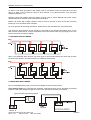
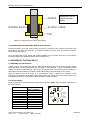
2.3 DETECTOR CIRCUIT WIRING
Depending on the model purchased two, four, six or eight Detector circuit connections are available
on the Fire Alarm Panel. A maximum of 32 devices (i.e. smoke detectors, heat detectors, or Manual
Call Points) can be fitted to each circuit.
Typical detector circuit wiring
=21( =21( 5
&$//
32,17
'LRGH
%DVH
5
&$//
32,17
5
5
(1' RI
/,1(
',2'(
1
'R QRW VSXU GHYLFHV EHFDXVH WKH\ ZLOO QRW EH PRQLWRUHG
or
=21( =21( &$//
32,17
&$//
32,17
5
5
5
5
(1' RI
/,1(
',2'(
1
,I $// WKH FDOO SRLQWV DUH FRQQHFWHG WR WKH VWDUW RI WKH ]RQH WKHQ
FRQYHQWLRQDO EDVHV FDQ EH XVHG LQVWHDG RI GLRGH EDVHV
Approved Document No: GLT.MAN-101T
Issue : 1.6s
Authorised: GH
Date: 06/11/2002
PAGE 4
PREMIER SX INSTALLATION MANUAL.
An End of Line diode (provided in the Panel) must be connected across the terminals of the last
device on each circuit to allow the wiring to be monitored. It is polarity sensitive, and connected
cathode (STRIPE) to +ve
Detector bases with integral continuity diodes must be used to ensure Manual Call Points remain
operational when a detector head is removed from its base.
Manual call points with integral resistors must be used to prevent a short circuit fault occurring
instead of a Fire Condition when activated.
For more specific device wiring information, please refer to the manufacturers’ own instructions.
The wiring for each Detector circuit should be connected to the relevant termination block on the
Main Control PCB and their screens terminated at the Panel’s base earth tag (see page 9 for more
precise second fix connection details).
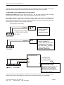
2.4 SOUNDER CIRCUIT WIRING
61'
61'
6281'(5
6281'(5
6281'(5
6281'(5
.
(QG RI
/LQH 5HVLVWRU
Note: If non-polarised alarm devices (eg some types of old mechanical bell) are used, then a diode
will have to be placed in line with the device to enable fault monitoring.
61'
&211(&725
%/2&.
61'
%(//
%(//
%(//
%(//
.
(QG RI
/LQH 5HVLVWRU
2.5 AUXILIARY INPUT WIRING
One non-latching auxiliary input connection is available on the Fire Alarm Panel.
Class Change Input (CC): Operates the Sounders continuously when the CC terminals are shorted
together. If the class change is triggered, it WILL NOT operate the Auxiliary Fire outputs.
Typical auxiliary input wiring options
&/$66
&+$1*(
&/$66
&+$1*(
Approved Document No: GLT.MAN-101T
Issue : 1.6s
Authorised: GH
Date: 06/11/2002
&0 12
$8; ),5( 5(/$<
QG)LUH$ODUP
PAGE 5
PREMIER SX INSTALLATION MANUAL.
The wiring for this input should be connected to the relevant terminal block on the Main Control PCB
and their screens terminated at the Panel’s base earth tag (see page 9 for more details).
2.6 AUXILIARY OUTPUT WIRING (DRY CONTACTS ONLY)
Auxiliary Fire Output (AUX): Turns on during any fire. Can be used for driving local fire fighting
equipment such as sprinkler systems, door release systems, roller shutter doors, etc.
Fault Output (FAULT): This Output is normally energised. When a Fault occurs, the Output turns
off to ensure failsafe operation even in the event of total power loss. That is, the normally open
contact will be closed when there is no fault, and open when there is a fault. This should be taken into
account when any device is connected to the fault relay.
Typical auxiliary output wiring
7ULJJHU,3
12 &0 1&
)$8/7
,1',&$7,21
'(9,&(
127(7+(1&&217$&7
,623(1:+(17+(5(,6
12)$8/7
The fault relay is
used to connect
to a remote
indication device
)$8/75(/$<
7ULJJHU,3
$872
',$/(5
12 &0 1&
),5(5(/$<
The fire relay can be
used to connect to
various devices which are
activated on a fire alarm.
Eg. Auto dialer , magnetic
door release (24V),
sprinkler system etc.
28767$7,21
),5(
,1387
)$8/7
,1387
12 &0 1& 12 &0 1&
),5( 5(/$<
)$8/7 5(/$<
72$''5(66$%/(
),5($/$503$1(/
/223
/223 Here the relays are used to
communicate with a larger
addressable fire alarm system. An
example use of this might be a
warehouse, which uses several
flame detectors, and needs to be
part of a larger system.
The wiring for each output should be connected to the relevant terminal block on the Main Control
PCB and their screens terminated at the Panel’s base earth tag (see page 9 for more details).
Approved Document No: GLT.MAN-101T
Issue : 1.6s
Authorised: GH
Date: 06/11/2002
PAGE 6
PREMIER SX INSTALLATION MANUAL.
3.ENCLOSURE MOUNTING
We recommend the lid and PCBs are now removed from site to prevent accidental damage. Storing
the PCBs in a suitable cardboard box will also guard them against mechanical damage.
3.1 REMOVING THE KNOCKOUTS
Decide carefully how the wiring will be brought into the Panel with reference to Figure 2 below and
remove the required knockout for cable entry.
The knockouts should be removed with a sharp tap in the rim of the knockout using a flat broad
bladed screwdriver. Use of excessive force could damage the enclosure around the knockout.
Always ensure if a knockout is removed, that the hole is filled with a good quality cable gland. Any
unused knockouts must be securely blanked off.
It is essential that the 230Va.c. Mains cable is fed into the enclosure via one of the inlets at the top
right hand corner of the enclosure. (For further CRITICAL information on Mains connection, please
refer to “Connecting the Mains” on Page 8).
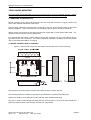
3.2 FIXING THE BACK BOX TO THE WALL
Figure 2: Internal view of back box with PCBs removed/side view for flush mounting.
[ PP JURPPHW FDEOH HQWULHV
PP
PP
[ PP
EDFN FDEOH
HQWU\
[ PP
EDFN FDEOH
HQWU\
PP
PP
PP
[ PP
NQRFNRXW
:DOO0RXQW
)OXVK0RXQW
FDEOH HQWULHV
Using the three mounting holes provided, fix the base securely onto/into the wall.
The mounting holes are suitable for use with No 8 roundhead or countersunk woodscrews.
Assess the condition and construction of the wall and use a suitable screw fixing.
Any dust or swarf created during the fixing process must be kept out of the Fire Alarm Panel and
great care must be taken not to damage any wiring or components.
Approved Document No: GLT.MAN-101T
Issue : 1.6s
Authorised: GH
Date: 06/11/2002
PAGE 7
PREMIER SX INSTALLATION MANUAL.
4 CONNECTING MAINS & BATTERY POWER
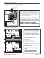
4.1 CONNECTING THE MAINS POWER
,1/(70$,16
6833/<
The panel should be connected to 220-240V AC by a 3A
2
2
rated spur to the fuse box with 0.75mm to 2.5mm 3-core
cable. Nothing else should be connected to this supply
The Live, Earth and Neutral connections are marked on the
PCB. The Mains is protected by a quick blow 20mm 1A
HBC fuse. (Also known as HRC)
The incoming mains cable should be kept separate from
the zone cables to help minimise mains interference.
Once the mains is connected, the protective cover should
be replaced BEFORE turning on the mains power. This will
minimise the chance of electric shock from the PCB.
,17(51$/:,5,1*
MAKE SURE ANY SPARE ENTRY HOLES ARE
COVERED WITH THE PLASTIC GROMMETS PROVIDED
Figure 3: Power Supply PCB layout and Mains connection details
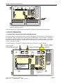
4.2 CONNECTING THE BATTERIES
Although there are many sizes of suitable
battery, the sizes we usually recommend are
12V 7Ah, or 12V 2Ah, and the enclosure has
been designed to hold these two sizes.
%$77(5<
,17(5&211(&7,1*
&$%/(
72 3&%
To calculate the exact requirement, use the
equation in section 10, but as a rough guide:2/4 Zones, 24 Hr standby – 2Ah
&/$03
6($/(' /($' $&,' %$77(5<
6($/(' /($' $&,' %$77(5<
9
9
$K
2/4 Zones, 48 Hr+ standby – 7Ah
$K
6/8 Zones – 7Ah
BATTERY CONNECTIONS
The two batteries are wired in series.
The +ve of one battery is connected to the red
battery lead.
The –ve of the other battery is connected to
the black battery lead.
72 3&%
%$77(5<
,17(5&211(&7,1*
&$%/(
[ $K %DWWHULHV
6($/(' /($' $&,' %$77(5<
9
$K
The –ve of the first battery is connected to the
+ve of the second battery using the link wire
supplied.
When fitting the batteries, take care not to
damage the temperature monitoring
thermistors. See figure 4a overleaf.
Figure 4: Battery location and connection details
Approved Document No: GLT.MAN-101T
Issue : 1.6s
Authorised: GH
Date: 06/11/2002
PAGE 8
PREMIER SX INSTALLATION MANUAL.
%$77(5<
,17(5&211(&7,1*
72 3&%
&$%/(
[ WKHUPLVWRUV
FDEOH WLHG
LQWR SODFH
6($/(' /($' $&,' %$77(5<
6($/(' /($' $&,' %$77(5<
9
9
$K
$K
Figure 4a:Thermistor location
These thermistors are used to prevent overcharging the batteries in high ambient temperatures.
5. DEVICE TERMINATION
5.1 CONNECTING THE DETECTOR AND SOUNDER CIRCUITS
All cables entering the enclosure should have brass cable glands, which will ensure a good ground to
the steel EMC cable grounding plate. Incoming Detector and Sounder circuits should be connected to
the relevant connector block on the Main Control PCB as shown in Figure 6 below. All screens
should be fed through the gland to make electrical contact with it. The last cable should also connect
to earth. (see Figure 6 & 6a)
For typical detector and sounder circuit wiring diagrams, please refer to pages 4 and 5.
6WHHO(0&
*URXQGLQJ3ODWH
,1/(70$,16
6833/<
%UDVV*ODQGV
0$,16 )86(
$ +5& &(5$0,&
&211 &211
MAKE SURE ANY SPARE
ENTRY HOLES ARE
COVERED WITH THE
PLASTIC GROMMETS
PROVIDED
)6
)6
61'
61'
P$
P$
)6
)6
)6
&+ $5*(5
(Q 683
%$77(5<
$
$
$
/,9( 1(87 ($57+
5$/
0$,16 72 75$16)250(5 35,0$5<
,17(51$/
:,5,1*
Figure 6: Detector and Sounder Circuit Connection
Approved Document No: GLT.MAN-101T
Issue : 1.6s
Authorised: GH
Date: 06/11/2002
PAGE 9
PREMIER SX INSTALLATION MANUAL.
*ODQG
5XEEHU6HDO
Expanded View Of
Gland & Screen
Cable
6FUHHQFDEOH
1XW
Figure 6a: Expanded view of brass cable gland.
5.2 CONNECTING THE AUXILIARY INPUTS AND OUTPUTS
Incoming auxiliary input and output cables should be connected to the relevant connector block
terminals on the Main Control PCB. If screened cables have been used, all screens should be
terminated as per figure 6.
For a full description of the inputs and outputs available on the Premier SX range of Fire Panels,
including typical wiring diagrams please refer to pages 5 & 6.
6. SOUNDER ACTIVATION DELAY
6.1 DECIDING TO USE A DELAY
A delay of up to nine minutes from the Fire Alarm Panel being triggered, to its Alarm sounder outputs
being activated, can be programmed into the panel by the Engineer. This is a particularly useful
feature for schools, nightclubs and other public places where the nuisance and panic caused by a
false alarm must be avoided. It should be noted that the delay period will apply to ALL zones.
When an Alarm occurs on any zone, it is processed as normal. However, the activation of the
sounders is postponed until the delay period has expired, thus allowing the cause of the Alarm to be
investigated by the User. If the alarm is false the alarm can be cancelled.
6.2 TO SET DELAY
Open the panel door using Alan Key provided and set switch 7 (SW7) using a terminal screw driver to
the delay required
SW7 Setting
0
1
2
3
4
5
6
7
8
9
External sounder
delay in minutes
No delay
1 minute
2 minutes
3 minutes
4 minutes
5 minutes
6 minutes
7 minutes
8 minutes
9 minutes
Approved Document No: GLT.MAN-101T
Issue : 1.6s
Authorised: GH
Date: 06/11/2002
PAGE 10
PREMIER SX INSTALLATION MANUAL.
6.3 DELAY INDICATION AND OVERRIDE
If a delay is set, the fire panel will light the General Disablement LED and Delay (DEL) LED to
indicate that the sounders are delayed. If an alarm occurs, the fire LEDs will light as usual, but the
sounders will not start until the delay period has expired. After the delay period, the Gen Disablement
and Delay LEDs will extinguish & the sounders will start.
Pressing the ‘sounder override’ switch will override the delay at any time and results in the sounders
being turned on immediately.
If on investigation, the panel was activated by a false alarm, turn the keyswitch to Controls Enabled,
and press the reset button. This will return the system to normal, without the sounders being
activated. (Assuming the cause of the false alarm has been removed).
The delay can be removed by either returning the rotary switch to position 0, or by turning keyswitch
to Controls Active, pressing Engineer, then pressing Delay override. (Continuing to press delay
override will toggle the delay on & off).
7. ZONE DISABLEMENT
7.1 WHY USE ZONE DISABLEMENT
To aid commissioning and assist routine maintenance checks, any of the zones or the sounder
circuits can be disabled.
When a zone (or sounder cct) is disabled, the panel will not respond to any fault or fire signals it
receives from that zone. This might be used if the system requires routine maintenance, and the
customer needs the system to continue running, but doesn’t want spurious false alarms.
The panel will respond in the usual manner to any events in any non-disabled zones.
7.2 TO PROGRAMME ZONE (OR SOUNDERS) AS DISABLED
Any number of zones (or the sounders) can be disabled, but it is good practice to only disable one
zone at a time.
1.
Insert and turn control key to enabled position;
2.
Press Engineer switch and the GENERAL DISABLEMENT LED will come on (flashing fast);
3.
Press Scroll switch and the GENERAL DISABLEMENT LED will flash slowly. The panel is now
in SELECT DISABLEMENT MODE.
4.
Press scroll button again. Zone 1 DISABLEMENT LED will be lit. Continue to press scroll until
the desired Zone or sounder is lit. Press the Engineer button. The GENERAL DISABLEMENT
LED will be lit constantly indicating that this zone (or sounder) is now disabled.
5.
If more than one zone needs to be disabled, then press scroll again until the required zone is
selected.
6.
If the panel needs to be taken out of SELECT DISABLEMENT MODE (eg to silence a fault on
another part of the system) , turn the keyswitch off, then back on again.
7.
Once all the work has been done the zones need to be enabled again. If the panel is still in
SELECT DISABLEMENT MODE, jump to paragraph 8, otherwise, turn the keyswitch to
controls enabled, press engineer button (GENERAL DISABLEMENT LED will flash fast). Press
scroll and it will return to being on steady. The panel is now in SELECT DISABLEMENT MODE
8.
Press the scroll button until the disabled zone has been selected. Press engineer button.
Scroll to any other disabled zone and enable in the same way. When all zones are enabled
again, the GENERAL DISABLEMENT LED will flash slowly. Turn the keyswitch to off to return
the system to normal.
Approved Document No: GLT.MAN-101T
Issue : 1.6s
Authorised: GH
Date: 06/11/2002
PAGE 11
PREMIER SX INSTALLATION MANUAL.
8. ZONE TEST
8.1 WHY USE ZONE TEST
To aid commissioning and assist routine maintenance check, a non-latching ‘one man test’ facility is
available.
When a detector or manual call point is triggered on any zone in Test, the Alarm sounders operate for
approximately seven seconds on and seven seconds off. This cycle continues until the cause of the
Alarm is removed (either by the test smoke clearing from the detector or the manual call point being
reset), at which point, the detector circuit also automatically resets.
Should an Alarm occur on a zone that is not programmed to test, the Alarm will be processed in the
normal way. The testing of the zone in test will temporarily be suspended until the Alarm(s) from the
other zones are reset. At this point, zone retesting may resume.
8.2 TO PROGRAMME ZONE IN TEST
NOTE: Only one zone can be programmed in test at any one time.
1. Insert and turn control key to enabled position;
2. Press engineer switch until the General Zone test LED is on (flashing fast);
3. Enter Engineer Code 4114 and then the General Zone Test LED is on (flashing slow);
4. Press scroll switch and Zone one fault LED will flash in synchronisation with the General Zone
test;
5. Press scroll button to the desired Zone for test. Once the desired Zone LED is flashing, this
Zone is now in test mode.
6. Once testing of that zone is completed, press scroll button to move to another Zone or turn the
control key switch to off position to exit test mode.
9. GENERAL FAULT FINDING
9.1 ZONE FAULTS
Open circuit faults will be indicated by zone(s) fault LED flashing. In case of a short circuit fault, then
the Zone(s) Fault LED will be accompanied by the Short Circuit Fault LED. In both cases, the
internal Fault Buzzer will sound and the General Fault LED will be lit.
The Zone Faults are non-latching faults. That is, if the fault disappears, the panel will automatically
reset itself. (after a short delay of up to a minute)
Suggested Action
a)
Disconnect the faulting detector zone completely and refit the end of line diode at that zone
terminal in the panel. If the fault condition for that zone clears, this confirms there is a wiring
fault.
b)
Double-check and refit the wiring and the end of line diode on the zone. Trace the fault with
consideration for the type of fault indicated.(HINT: splitting the cable half way down the zone,
and fitting the end of line diode to the new end point helps to determine which section of cable
is giving the fault)
Note: A common fault is a detector head badly seated in a base that is not making the
connection.
d)
A short circuit on a zone could be caused by the end of line diode being fitted backwards.
c)
Check that the detectors are compatible with this FACP. Note that some makes of detector will
require a series resistor or diode to be fitted to work properly. There is usually a spare
connector on the base to accommodate this (check instructions that came with the detector).
Approved Document No: GLT.MAN-101T
Issue : 1.6s
Authorised: GH
Date: 06/11/2002
PAGE 12
PREMIER SX INSTALLATION MANUAL.
9.2 SYSTEM FAULT
A system fault is an abnormal microprocessor running condition due to various unexpected
phenomena
This will result in the panel attempting to correct itself. Should this fault occur, the System Fault LED,
General Fault LED, General Fault relay and fault internal buzzer will be constantly active until the
control keyswitch is turned from off position to control enable position. This should cause this fault
condition to reset. If not, consult your supplier
9.3 SUPPLY FAULTS
A power supply fault is indicative of one or more of the following faults: 1.Loss of Mains power – Remedy
a.
b.
Check mains fuse (Conn 5). Also, check that main power is present.
Check charger fuse FS1.
2.Loss of Battery power – Remedy
a.
b.
Check battery fuse FS2.
Check that battery connections are secure.
3.Low Battery – Remedy
a.
Check battery voltage.
4.Wrong Charging Voltage.
o
The charging voltage should be 28.4V off load at 25 C. If it has been altered, reset using
potentiometer VR1
5. Overcharged Batteries.
Remove the batteries and measure the voltage. If it is reading over 27.4 then the batteries
are overcharged. Try to run the panel on batteries only for half an hour or so to try to
discharge the batteries. If this doesn’t solve the problem, replacement batteries will be
required.
9.4 EARTH FAULTS
An EARTH fault indicates that something is shorting to earth (usually through the cable screen).
Disconnect the earth screens one at a time to determine the problem line.
(Note: connecting other equipment , eg an oscilloscope , to the panel can give an earth fault)
The voltage between battery –Ve and earth should be 14-16 volts. If it is not, the voltage should
indicate what is shorting to earth.
9.5 SOUNDER FAULTS
Check that the correct END of Line resistor has been fitted. (10K – brown, black, orange, gold)
Check that both fuses are OK (FS4 & FS5 – 400mA QB)
If working on an existing installation, check that the devices are polarised.
Check cable continuity (remove from panel and measure continuity. Should read 10K)
Approved Document No: GLT.MAN-101T
Issue : 1.6s
Authorised: GH
Date: 06/11/2002
PAGE 13
PREMIER SX INSTALLATION MANUAL.
10. STANDBY BATTERY CALCULATION GUIDE
The standby time of the Fire Alarm Panel after the mains has failed depends on the quiescent loading
of the Panel. The alarm load of the panel and the capacity of the batteries.
To determine the capacity of batteries required for any given standby period, the following formula
should be used: -
Standby Time in Ahr = 1.25 x [(Ta x Ia) + (Ts x (Iqp+Iqz))]
The multiplier 1.25 is present to account for lost capacity over the life of the batteries.
Ts = Number of hours standby required
Iqp = The quiescent current of the Panel = 0.048A (48mA)
This figure is with the Mains failed, buzzer operative and the Power Supply and General Fault
indicators lit. If there are other quiescent drains on the Panel then these must be added .
Iqz = The total quiescent current of all zone devices
As a guideline, the quiescent current of most modern detectors is typically 0.00005A (50uA), and that
of manual call points is zero. To obtain the most accurate figures consult the devices manufacturers’
specification.
Ia = The total alarm current of the sounders (plus any other devices being supplied by the panel in
an alarm condition).
Ta = The amount of time in hours required for the alarm (most commonly being half an hour).
Example 1
Panel has a total of 50 detectors each consuming 50uA each, 20 Sounders at 20mA each, the
required standby time is 24 hours and the alarm time is 0.5 hours.
Iqz = 50 x 0.00005 = 0.0025A
Iqp = 0.050A
Ia = 20 x 0.02 = 0.4A
Ts = 24 hr
Ta = 0.5 hr
Standby Time in Ahr = 1.25 x ((0.5 x 0.4) + (24 x (0.50 + 0.0025))) = 1.825 Ahr
(Suggested Batteries 2 x 12V , 2.2Ahr)
Example 2
Panel has a total of 100 detectors each consuming 40uA each, 40 Sounders at 20mA each, the
required standby time is 72 hours and the alarm time is 1 hour.
Iqz = 100 x 0.0000 = 0.004A
Iqp = 0.050A
Ia = 40 x 0.02 = 0.8A
Ts = 72 hr
Ta = 1 hr
Standby Time in Ahr = 1.25 x (1 x 0.8 + 72 x (.050 + 0.004)) = 5.9 Ahr
(Suggested Batteries 2 x 12V , 6Ahr)
Approved Document No: GLT.MAN-101T
Issue : 1.6s
Authorised: GH
Date: 06/11/2002
PAGE 14
PREMIER SX INSTALLATION MANUAL.
11. PCB TERMINATION CONNECTIONS.
0$,16 )86(
$ +5& &(5$0,&
&211 &211
)6
)6
61'
61'
P$
P$
)6
)6
)6
&+$5*(5
(Q 683
%$77(5<
$
$
$
/,9( 1(87 ($57+
5$/
0$,16 72 75$16)250(5 35,0$5<
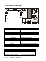
11.1 CONNECTIONS
Connection No
1
2
3
4
5
6
7
8
9
10
11
12
13
14
15
16
17
18
19
20
Description
ZONE 1 +&ZONE 2 +&ZONE 3 +&ZONE 4 +&ZONE 5 +&ZONE 6 +&ZONE 7 +&ZONE 8 +&SND 1 +&SND 2 +&CLASS CHANGE
FIRE RELAY NO/CM/NC
FAULT RELAY NO/CM/NC
BATTERY + & AC AC
EN54 supply - & +
CONN 1
CONN 27
CONN 26
CONN 5
Use
Connect to Zone 1
Connect to Zone 2
Connect to Zone 3
Connect to Zone 4
Connect to Zone 5
Connect to Zone 6
Connect to Zone 7
Connect to Zone 8
Connect to sounder circuit 1 (sirens/bells)
Connect to sounder circuit 2 (sirens/bells)
Join terminals to activate sounders
Activates on fire (including test mode)
Normally powered ie NO is closed with no fault
Connect 2 x 12V SLA batteries in SERIES (ie 24V)
Connected to transformer secondary (30VAC)
NOT CONNECTED IN STAND ALONE PANEL.
20 way ribbon cable to display PCB
EARTH connection to display PCB & SCREEN TAG
Filtered mains to transformer
MAINS TERMINAL BLOCK
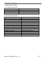
11.2 FUSES
FUSE NO
FS1
FS2
FS3
FS4
FS5
INLET FUSE
DESCRIPTION
Charger Fuse
Battery Fuse
EN54 SUPPLY (NOT USED)
Sounder circuit 1
Sounder circuit 2
Mains Protection Fuse
Approved Document No: GLT.MAN-101T
Issue : 1.6s
Authorised: GH
Date: 06/11/2002
RATING
1.6A time delay 5 x 20mm glass
1.6A time delay 5 x 20mm glass
1.6A time delay 5 x 20mm glass
400mA time delay 5 x 20mm glass
400mA time delay 5 x 20mm glass
1A Quick Blow HBC 5 x 20mm ceramic
PAGE 15
PREMIER SX INSTALLATION MANUAL.
12. PANEL SPECIFICATIONS
12.1 ENCLOSURE SPECIFICATIONS
DESCRIPTION
VALUE
ENCLOSURE SIZE
TOP CABLE ENTRIES
BOTTOM CABLE ENTRIES
REAR CABLE ENTRIES
355 x 275 x 100 mm
12 x 19mm DIA GROMMETED ENTRIES
2 x 19mm KNOCKOUT ENTRIES
2 SNAP OUTS, 60 x 20mm
12.2 ELECTRICAL SPECIFICATIONS
ELECTRICAL DESCRIPTION
VALUE
MAINS VOLTAGE
BATTERY VOLTAGE
SYSTEM VOLTAGE
SYSTEM VOLTAGE RIPPLE
CHARGER SIZE
ZONE VOLTAGE
SOUNDER ALARM OUTPUTS
AUXILIARY FAULT OUTPUT
AUXILIARY FIRE OUTPUT
NUMBER OF ZONES
MAXIMUM ZONE CAPACITY
MAXIMUM ZONE RESISTANCE
REMOTE SOUNDER ACTIVATION
SOUNDER ACTIVATION DELAY
ZONE END OF LINE DEVICE
SOUNDER END OF LINE DEVICE
CHARGER VOLTAGE
ZONE SHORT CIRCUIT PROTECTION
CHARGER SHORT CIRCUIT PROTECTION
TOTAL CHARGER OUTPUT
230V AC +/- 10% @ 50/60 Hz
24V DC (2 X 12V SLA BATTERY)
24V DC NOMINAL (18 – 32 V)
2V PK-PK MAX
UP TO 7AH in 24 Hours
21V DC NOMINAL (20 - 22.5V)
2 x 400mA @ 24V DC (Nominal)
1 x RELAY SELV (1A MAX)
1 x RELAY SELV (1A MAX)
1/2/4/6/8
32 DEVICES PER ZONE
80 ohms
VIA N/O CONTACTS
0-9 MINUTES -IN 1 MIN INCREMENTS
DIODE (CATHODE STRIPE TO +)
10 K RESISTOR
o
28.4V @ 25 C (NO BATTERY CONNECTED)
100mA
Batteries less than 20V
1.1 Amp
Approved Document No: GLT.MAN-101T
Issue : 1.6s
Authorised: GH
Date: 06/11/2002
PAGE 16