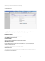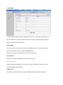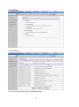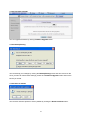
1
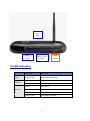
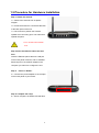
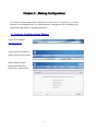
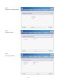
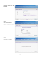
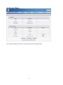
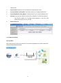
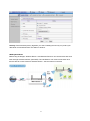
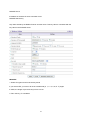
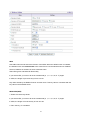
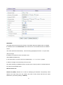
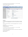
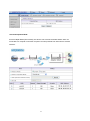
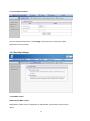
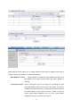
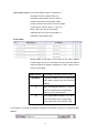
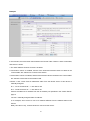
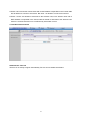
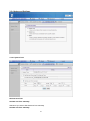
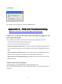
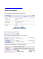
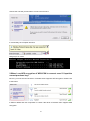
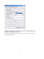
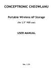
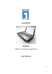
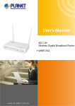
LevelOne
User Manual
WAP-6003
150Mbps Wireless Access Point
Ver. 1.0
1
Safety
FCC WARNING
This equipment may generate or use radio frequency energy. Changes or
modifications to this equipment may cause harmful interference unless the
modifications are expressly approved in the instruction manual. The user
could lose the authority to operate this equipment if an unauthorized change or
modification is made.
This equipment has been tested and found to comply with the limits for a Class
B digital device, pursuant to Part 15 of the FCC Rules. These limits are
designed to provide reasonable protection against harmful interference in a
residential installation. This equipment generates, uses, and can radiate radio
frequency energy and, if not installed and used in accordance with the
instructions, may cause harmful interference to radio communications.
However, there is no guarantee that interference will not occur in a particular
installation. If this equipment does cause harmful interference to radio or
television reception, which can be determined by turning the equipment off
and on, the user is encouraged to try to correct the interference by one or
more of the following measures:
1) Reorient or relocate the receiving antenna.
2) Increase the separation between the equipment and receiver.
3) Connect the equipment into an outlet on a circuit different from that
to which the receiver is connected.
4) Consult the dealer or an experienced radio/TV technician for help.
CE Declaration of conformity
This equipment complies with the requirements relating to electromagnetic
compatibility, EN 55022 class B for ITE, the essential protection requirement of
Council Directive 89/336/EEC on the approximation of the laws of the Member
States relating to electromagnetic compatibility.
CE Marking Warning
Hereby, Digital Data Communications, declares that this product is in
compliance with the essential requirements and other relevant provisions of
Directive 1999/5/EC.
The CE-Declaration of Conformity can be downloaded at:
http://www.levelone.eu/support.php
2
NCC Marking Warning
第十二條
型式認證合格之低功率射頻電機,非經許可,公司、商號或使用者均不得擅自變更頻率、加大
功率或變更原設計之特性及功能。
第十四條
低功率射頻電機之使用不得影響飛航安全及干擾合法通信;經發現有干擾現象時,應立即停用,
並改善至無干擾時方得繼續使用。
前項合法通信,指依電信法規定作業之無線電通信。
低功率射頻電機須忍受合法通信或工業、科學及醫療用電波輻射性電機設備之干擾。
General Public License
This product incorporates open source code into the software and therefore
falls under the guidelines governed by the General Public License (GPL)
agreement.
Adhering to the GPL requirements, the open source code and open source
license for the source code are available for free download at
http://global.level1.com.
If you would like a copy of the GPL or other open source code in this software
on a physical CD medium, LevelOne (Digital Data Communications) offers to
mail this CD to you upon request, for a price of US$9.99 plus the cost of
shipping.
3
Table of Contents
Chapter 1 Introduction ...............................................................................................5
1.1 Packing List ..................................................................................................5
1.2 Spec Summary Table ..................................................................................5
1. Package Information ..............................................................................................6
1.3 Hardware Configuration..............................................................................6
1.5 Procedure for Hardware Installation ...............................................................8
Chapter 3 Making Configuration ...........................................................................9
3.1 Login to Configure from Wizard ....................................................................9
3.2 System Status ............................................................................................12
3.3 Advanced ....................................................................................................13
Appendix A FAQ and Troubleshooting ...................................................................43
What can I do when I have some trouble at the first time?.................................43
How do I connect router by using wireless? .......................................................44
IP Address
192.168.1.1
Password
admin
Wireless Mode
Enable
Wireless SSID
LevelOne
Wireless Security
None
4
Chapter 1 Introduction
Congratulations on your purchase of this outstanding Wireless Broadband Router. This
product is specifically designed for Small Office and Home Office needs. It is easy to configure
and operate even for non-technical users. Instructions for installing and configuring this
product can be found in this manual. Before you install and use this product, please read this
manual carefully for fully exploiting the functions of this product.
1.1 Packing List
WAP-6003
Power Adapter
Antenna (x1)
Network Cable
Quick Installation Guide
CD User Manual / Utility / QIG
1.2 Spec Summary Table
Device Interface
Ethernet LAN
5 x RJ-45 port, 10/100Mbps, auto-MDI/MDIX
Antenna
2 dBi fixed antenna
WPS Button
/Wireless On
For WPS connection and Enable “Wireless Function”
Reset Button
Reset to Factory Default setting
LED Indication
Status / LAN1 ~ LAN5/ WiFi
Power Jack
DC Power Jack, powered via external DC 5V/1A
switching power adapter
Wireless LAN (WiFi)
Standard
IEEE 802.11b/g/n-lite compliance
SSID
SSID broadcast or in stealth mode
Channel
Auto-selection, manually
Security
WEP, WPA, WPA-PSK, WPA2, WPA2-PSK
WPS
WPS (Wi-Fi Protected Setup)
WMM
WMM (Wi-Fi Multimedia)
Functionality
5
Routing Protocol
Static route, dynamic route (RIP v1/v2)
Management
SNMP, syslog,
Administration
Web-based UI, remote login, backup/restore setting
Environment & Certification
Package
Information
DC 5V/1A power adapter, Quick Installation Guide
1. Package
Information
Device dimension (mm) 185 x 119 x 32 mm
Operation Temp.
Temp.: 0~40oC, Humidity 10%~90% non-condensing
Storage Temp.
Temp.: -10~70oC, Humidity: 0~95% non-condensing
EMI Certification
CE/FCC compliance
RoHS
RoHS compliance
*Specifications are subject to change without prior notice.
1.3 Hardware Configuration
Figure 2-1 Front Panel
Antenna
Power Jack
Auto MDI/MDIX RJ-45 Ports
Automatically sense the types of LAN
when connecting to Ethernet
6
Reset Button
Wi-Fi
LED
Status
LAN1~LAN5
WPS
LED
LEDs
Button
1.4 LED indicators
Status
LED status
Description
Green in flash
Device status is working.
Green
RJ45 cable is plugged
Green in flash
Data access
Green
WLAN is on
Green in flash
Data access
Green in fast flash
Device is in WPS PBC mode
Green in dark
Wi-Fi Radio is disabled
LAN LED
WiFi LED
7
1.5 Procedure for Hardware Installation
Step 1. Attach the antenna.
1.1. Remove the antenna from its plastic
wrapper.
1.2. Screw the antenna in a clockwise direction
to the back panel of the unit.
1.3. Once secured, position the antenna
upward at its connecting joint. This will ensure
optimal reception.
1.Turn off the Power Switch
first.
Step 2 Insert the Ethernet cable into LAN
Port:
Insert the Ethernet patch cable into LAN port
on the back panel of Router, and an available
Ethernet port on the network adapter in the
computer you will use to configure the unit.
Step 4.
Power on Router:
4.1. Connect the power adapter to the receptor
on the back panel of your Router.
Step 5. Complete the setup.
5.1. When complete, the Status LED will flash.
8
C
Chhaapptteerr 33 M
Maakkiinngg C
Coonnffiigguurraattiioonn
This product provides Web based configuration scheme, that is, configuring by your Web
browser, such as Mozilla Firefox or or Internet Explorer. This approach can be adopted in any
MS Windows, Macintosh or UNIX based platforms.
3.1 Login to Configure from Wizard
Type in the IP Address
(http://192.168.1.1)
Type password, the default is
“admin” and click ‘login’ button.
Press “Wizard” for basic
settings with simple way,
Press “Next” to start wizard.
9
Step 1:
Set up your system password.
Step 2:
Setup the LAN IP
Step 3:
Set up your Wireless.
10
Set up your Authentication and
Encryption.
Step 4:
Then click Apply Setting.
And then the device will reboot.
Step 5:
Click Finish to complete it.
11
3.2 System Status
This option provides the function for observing this product’s working status:
12
3.3 Advanced
3.3.1 Basic Setting
Please Select “Advanced Setup” to Setup
13
1. LAN IP Address: the local IP address of this device. The computers on your network
must use the LAN IP address of your product as their Default Gateway. You can change it
if necessary.
3.3.1.2 DHCP Server
Press “More>>”
1.
DHCP Server: Choose “Disable” or “Enable.”
2.
Lease time: This is the length of time that the client may use the IP address it has
been
Assigned by dhcp server.
3.
IP pool starting Address/ IP pool starting Address: Whenever there is a request,
the DHCP
server will automatically allocate an unused IP address from the IP address pool to
the requesting computer. You must specify the starting and ending address of the IP
14
address pool.
4.
Domain Name: Optional, this information will be passed to the client.
5.
Primary DNS/Secondary DNS: This feature allows you to assign DNS Servers
6.
Primary WINS/Secondary WINS: This feature allows you to assign WINS Servers
7.
Gateway: The Gateway Address would be the IP address of an alternate Gateway.
This function enables you to assign another gateway to your PC, when
DHCP server offers an IP to your PC.
8.
DHCP Client List:
3.3.1.3 Wireless Setting
AP only Mode:
When acting as an access point, this device connects all the stations to a wired network and
See the sample application below.
15
Network ID (SSID): Network ID is used for identifying the Wireless LAN (WLAN). Client
stations can roam freely over this product and other Access Points that have the same
Network ID. (The factory setting is “default”)
SSID Broadcast: The router will Broadcast beacons that have some information, including
ssid so that
The wireless clients can know how many ap devices by scanning function in the network.
Therefore, This function is disabled, the wireless clients can not find the device from beacons.
Channel: The radio channel number. The permissible channels depend on the Regulatory
Domain.
WPS (WiFi Protection Setup)
WPS is WiFi Protection Setup which is similar to WCN-NET and offers safe and
easy way in Wireless Connection.
16
Security: Select the data privacy algorithm you want. Enabling the security can protect your
data while it is transferred from one station to another.
WDS Hybrid Mode:
While acting as Bridges, Wireless Router 1 and Wireless Router 2 can communicate with each
other through wireless interface (with WDS). Thus All Stations can communicate each other
and are able to access Internet if Wireless Router 1 has the Internet connection
17
Wireless Off Schedule: Before turning Off Wireless Radio, the device will detect if Wireless
station is online, then depend as Schedule ” 01:00~08:30” to disable WiFi service.
Network ID (SSID): Network ID is used for identifying the Wireless LAN (WLAN). Client
stations can roam freely over this product and other Access Points that have the same
Network ID. (The factory setting is “default”)
SSID Broadcast: The router will Broadcast beacons that have some information, including
ssid so that
The wireless clients can know how many ap devices by scanning function in the network.
Therefore, This function is disabled, the wireless clients can not find the device from beacons.
Channel: The radio channel number. The permissible channels depend on the Regulatory
Domain.
Security: Select the data privacy algorithm you want. Enabling the security can protect your
18
data while it is transferred from one station to another.
Remote AP MAC : Choose “Manual” or scan one AP to copy to item1~4.
WDS(Wireless Distribution System)
The WDS (Wireless Distributed System) function let this access point acts as a wireless
LAN access point and repeater at the same time. Users can use this feature to build up a
large wireless network in a large space like airports, hotels and schools …etc.
19
Network ID (SSID): Network ID is used for identifying the Wireless LAN (WLAN). Client
stations can roam freely over this product and other Access Points that have the same
Network ID. (The factory setting is “default”)
SSID Broadcast: The router will Broadcast beacons that have some information, including
ssid so that
The wireless clients can know how many ap devices by scanning function in the network.
Therefore, This function is disabled, the wireless clients can not find the device from beacons.
Channel: The radio channel number. The permissible channels depend on the Regulatory
Domain.
Security: Select the data privacy algorithm you want. Enabling the security can protect your
data while it is transferred from one station to another.
Remote AP MAC : Choose “Manual” or scan one AP to copy to item1~4.
20
Universal Repeater Mode
Universal Repeater is a technology used to extend wireless coverage.
It provides the function to act as Adapter (client) and AP at the same time and can use this
function to connect to a Root AP and use AP(SSID name is same with Root AP ) function to
service all wireless stations within its coverage. All the stations within the coverage of this
access point can be bridged to the Root AP.
SSID (Wireless Network Name): Select “AP” or entry SSID manually to connect.
Security “There are several security types to use:
WEP :
When you enable the 128 or 64 bit WEP key security, please select one WEP key to be used
and input 26 or 10 hexadecimal (0, 1, 2…8, 9, A, B…F) digits.
802.1X
Check Box was used to switch the function of the 802.1X. When the 802.1X function is
enabled, the Wireless user must authenticate to this router first to use the Network service.
21
RADIUS Server
IP address or the 802.1X server’s domain-name.
RADIUS Shared Key
Key value shared by the RADIUS server and this router. This key value is consistent with the
key value in the RADIUS server.
WPA-PSK
1. Select Encryption and Pre-share Key Mode
If you select HEX, you have to fill in 64 hexadecimal (0, 1, 2…8, 9, A, B…F) digits
If ASCII, the length of pre-share key is from 8 to 63.
2. Fill in the key, Ex 12345678
22
WPA
Check Box was used to switch the function of the WPA. When the WPA function is enabled,
the Wireless user must authenticate to this router first to use the Network service. RADIUS
Server IP address or the 802.1X server’s domain-name.
Select Encryption and RADIUS Shared Key
If you select HEX, you have to fill in 64 hexadecimal (0, 1, 2…8, 9, A, B…F) digits
If ASCII, the length of pre-share key is from 8 to 63.
Key value shared by the RADIUS server and this router. This key value is consistent with the
key value in the RADIUS server.
WPA2-PSK(AES)
1. Select Pre-share Key Mode
If you select HEX, you have to fill in 64 hexadecimal (0, 1, 2…8, 9, A, B…F) digits
If ASCII, the length of Pre-share key is from 8 to 63.
2. Fill in the key, Ex 12345678
23
WPA2(AES)
Check Box was used to switch the function of the WPA. When the WPA function is enabled,
the Wireless user must authenticate to this router first to use the Network service. RADIUS
Server
IP address or the 802.1X server’s domain-name.
Select RADIUS Shared Key
If you select HEX, you have to fill in 64 hexadecimal (0, 1, 2…8, 9, A, B…F) digits
If ASCII, the length of Pre-share key is from 8 to 63.
Key value shared by the RADIUS server and this router. This key value is consistent with the
key value in the RADIUS server.
WPA-PSK /WPA2-PSK
The router will detect automatically
which Security type the client
uses to encrypt.
1. Select Pre-share Key Mode
If you select HEX, you have to fill in 64 hexadecimal (0, 1, 2…8, 9, A, B…F) digits
If ASCII, the length of Pre-share key is from 8 to 63.
2. Fill in the key, Ex 12345678
24
WPA/WPA2
Check Box was used to switch the function of the WPA. When the WPA function is enabled,
the Wireless user must authenticate to this router first to use the Network service. RADIUS
Server
The router will detect automatically
which Security type(Wpa-psk version 1 or 2) the client
uses to encrypt.
IP address or the 802.1X server’s domain-name.
Select RADIUS Shared Key
If you select HEX, you have to fill in 64 hexadecimal (0, 1, 2…8, 9, A, B…F) digits
If ASCII, the length of Pre-share key is from 8 to 63.
Key value shared by the RADIUS server and this router. This key value is consistent with the
key value in the RADIUS server.
Wireless Client List
Network ID (SSID): Network ID is used for identifying the Wireless LAN (WLAN). Client
stations can roam freely over this product and other Access Points that have the same
Network ID. (The factory setting is “default”)
25
SSID Broadcast: The router will Broadcast beacons that have some information, including
ssid so that
The wireless clients can know how many ap devices by scanning function in the network.
Therefore,
This function is disabled, the wireless clients can not find the device from beacons.
Channel: The radio channel number. The permissible channels depend on the Regulatory
Domain.
WPS (WiFi Protection Setup)
WPS is WiFi Protection Setup which is similar to WCN-NET and offers safe and
easy way in Wireless Connection.
WDS(Wireless Distribution System)
WDS operation as defined by the IEEE802.11 standard has been made available. Using WDS
it is possible to wirelessly connect Access Points, and in doing so extend a wired infrastructure
to locations where cabling is not possible or inefficient to implement.
26
Security: Select the data privacy algorithm you want. Enabling the security can protect your
data while it is transferred from one station to another.
There are several security types to use:
WEP :
When you enable the 128 or 64 bit WEP key security, please select one WEP key to be used
and input 26 or 10 hexadecimal (0, 1, 2…8, 9, A, B…F) digits.
802.1X
Check Box was used to switch the function of the 802.1X. When the 802.1X function is
enabled, the Wireless user must authenticate to this router first to use the Network service.
RADIUS Server
IP address or the 802.1X server’s domain-name.
RADIUS Shared Key
Key value shared by the RADIUS server and this router. This key value is consistent with the
key value in the RADIUS server.
27
WPA-PSK
1. Select Encryption and Pre-share Key Mode
If you select HEX, you have to fill in 64 hexadecimal (0, 1, 2…8, 9, A, B…F) digits
If ASCII, the length of pre-share key is from 8 to 63.
2. Fill in the key, Ex 12345678
28
WPA
Check Box was used to switch the function of the WPA. When the WPA function is enabled,
the Wireless user must authenticate to this router first to use the Network service. RADIUS
Server IP address or the 802.1X server’s domain-name.
Select Encryption and RADIUS Shared Key
If you select HEX, you have to fill in 64 hexadecimal (0, 1, 2…8, 9, A, B…F) digits
If ASCII, the length of pre-share key is from 8 to 63.
Key value shared by the RADIUS server and this router. This key value is consistent with the
key value in the RADIUS server.
WPA2-PSK(AES)
1. Select Pre-share Key Mode
If you select HEX, you have to fill in 64 hexadecimal (0, 1, 2…8, 9, A, B…F) digits
If ASCII, the length of Pre-share key is from 8 to 63.
2. Fill in the key, Ex 12345678
WPA2(AES)
Check Box was used to switch the function of the WPA. When the WPA function is enabled,
the Wireless user must authenticate to this router first to use the Network service. RADIUS
Server
IP address or the 802.1X server’s domain-name.
Select RADIUS Shared Key
If you select HEX, you have to fill in 64 hexadecimal (0, 1, 2…8, 9, A, B…F) digits
If ASCII, the length of Pre-share key is from 8 to 63.
Key value shared by the RADIUS server and this router. This key value is consistent with the
key value in the RADIUS server.
WPA-PSK /WPA2-PSK
The router will detect automatically
which Security type the client
uses to encrypt.
1. Select Pre-share Key Mode
29
If you select HEX, you have to fill in 64 hexadecimal (0, 1, 2…8, 9, A, B…F) digits
If ASCII, the length of Pre-share key is from 8 to 63.
2. Fill in the key, Ex 12345678
WPA/WPA2
Check Box was used to switch the function of the WPA. When the WPA function is enabled,
the Wireless user must authenticate to this router first to use the Network service. RADIUS
Server
The router will detect automatically
which Security type(Wpa-psk version 1 or 2) the client
uses to encrypt.
IP address or the 802.1X server’s domain-name.
Select RADIUS Shared Key
If you select HEX, you have to fill in 64 hexadecimal (0, 1, 2…8, 9, A, B…F) digits
If ASCII, the length of Pre-share key is from 8 to 63.
Key value shared by the RADIUS server and this router. This key value is consistent with the
key value in the RADIUS server.
Wireless Client List
30
Universal Repeater Mode
If set to Adapter Mode (Client mode), this device can work like a wireless station when it’s
connected to a computer so that the computer can send packets from wired end to wireless
interface.
31
3.3.1.4 Change Password
You can change Password here. We strongly recommend you to change the system
password for security reason.
3.3.3 Security Settings
3.3.3.4 MAC control
Administrator MAC Control
Regardless the MAC access configuration of administrator, specific MAC can access the
device.
32
MAC Address Control allows you to assign different access right for different users and to
assign a specific IP address to a certain MAC address.
MAC Address Control
Check “Enable” to enable the “MAC Address Control”. All of
the settings in this page will take effect only when “Enable” is
checked.
Connection control
Check "Connection control" to enable the controlling of which
wired and wireless clients can connect to this device. If a client is
denied to connect to this device, it means the client can't access to
the Internet either. Choose "allow" or "deny" to allow or deny the
clients, whose MAC addresses are not in the "Control table"
(please see below), to connect to this device.
33
Association control Check "Association control" to enable the
controlling of which wireless client can
associate to the wireless LAN. If a client is
denied to associate to the wireless LAN, it
means the client can't send or receive any data
via this device. Choose "allow" or "deny" to
allow or deny the clients, whose MAC
addresses are not in the "Control table", to
associate to the wireless LAN.
Control table
"Control table" is the table at the bottom of the "MAC Address
Control" page. Each row of this table indicates the MAC address
and the expected IP address mapping of a client. There are four
columns in this table:
MAC Address
IP Address
MAC address indicates a specific client.
Expected IP address of the corresponding
client. Keep it empty if you don't care its IP
address.
C
When "Connection control" is checked,
check "C" will allow the corresponding
client to connect to this device.
A
When "Association control" is checked,
check "A" will allow the corresponding
client to associate to the wireless LAN.
In this page, we provide the following Combobox and button to help you to input the MAC
address.
34
You can select a specific client in the “DHCP clients” Combobox, and then click on the “Copy
to” button to copy the MAC address of the client you select to the ID selected in the “ID”
Combobox.
Previous page and Next Page To make this setup page simple and clear, we have divided
the “Control table” into several pages. You can use these
buttons to navigate to different pages.
35
Example:
In this scenario, there are three clients listed in the Control Table. Clients 1 and 2 are wireless,
and client 3 is wired.
1.The "MAC Address Control" function is enabled.
2."Connection control" is enabled, and all of the wired and wireless clients not listed in the
"Control table" are "allowed" to connect to this device.
3."Association control" is enabled, and all of the wireless clients not listed in the "Control table"
are "denied" to associate to the wireless LAN.
4.Clients 1 and 3 have fixed IP addresses either from the DHCP server of this device or
manually assigned:
ID 1 - "00-12-34-56-78-90" --> 192.168.12.100
ID 3 - "00-98-76-54-32-10" --> 192.168.12.101
Client 2 will obtain its IP address from the IP Address pool specified in the "DHCP Server"
page or
can use a manually assigned static IP address.
If, for example, client 3 tries to use an IP address different from the address listed in the
Control
table (192.168.12.101), it will be denied to connect to this device.
36
5.Clients 2 and 3 and other wired clients with a MAC address unspecified in the Control table
are all allowed to connect to this device. But client 1 is denied to connect to this device.
6.Clients 1 and 2 are allowed to associate to the wireless LAN, but a wireless client with a
MAC address not specified in the Control table is denied to associate to the wireless LAN.
Client 3 is a wired client and so is not affected by Association control.
3.3.3.5 Miscellaneous Items
Administrator Time-out
The time of no activity to logout automatically. Set it to zero to disable this feature.
37
3.3.4 Advanced Settings
3.3.4.1 System Time
Get Date and Time
Set Date and Time manually
Selected if you want to Set Date and Time manually.
Set Date and Time manually
38
Selected if you want to Set Date and Time manually.
3.3.4.2 System Log
This page support two methods to export system logs to specific destination by means of
syslog(UDP) and SMTP(TCP). The items you have to setup including:
IP Address for Syslog
Host IP of destination where syslogs will be sent to.
Check Enable to enable this function.
E-mail Alert Enable
Check if you want to enable Email alert (send syslog via email).
SMTP Server IP and Port
Input the SMTP server IP and port, which are concated with ':'. If you do not specify port
number, the default value is 25.
For example, "mail.your_url.com" or "192.168.1.100:26".
Send E-mail alert to
The recipients who will receive these logs. You can assign more than 1 recipient, using ';' or ','
to separate these email addresses.
39
3.3.4.4 SNMP
In brief, SNMP, the Simple Network Management Protocol, is a protocol designed to give a
user the capability to remotely manage a computer network by polling and setting terminal
values and monitoring network events.
Enable SNMP
You must check Local, Remote or both to enable SNMP function. If Local is checked, this
device will response request from LAN. Get Community
Setting the community of GetRequest your device will response.
Set Community
Setting the community of SetRequest your device will accept.
IP 1, IP 2, IP 3, IP 4
Input your SNMP Management PC’s IP here. User has to configure to where this device
should send SNMP Trap message.
SNMP Version
Please select proper SNMP Version that your SNMP Management software supports.
40
3.3.5 Toolbox
3.3.5.1 View Log
You can View system log by clicking the View Log button
41
3.3.5.2 Firmware Upgrade
You can upgrade firmware by clicking Firmware Upgrade button.
3.3.5.3 Backup Setting
You can backup your settings by clicking the Backup Setting button and save it as a bin file.
Once you want to restore these settings, please click Firmware Upgrade button and use the
bin file you saved.
3.3.5.4 Reset to default
You can also reset this product to factory default by clicking the Reset to default button.
42
3.3.5.5 Reboot
You can also reboot this product by clicking the Reboot button.
Appendix A FAQ and Troubleshooting
What can I do when I have some trouble at the first time?
1.Why can I not connect the router even if the cable is plugged in Lan
port and the led is light?
A: First, please check Status Led. If the device is normal, the led will blink per second.
If not, please check How blinking Status led shows.
There are many abnormal symptoms as below:
Status Led is bright or dark in work: The system hanged up .Suggest powering off and on
the router. But this symptom often occurs, please reset to default or upgrade latest fw to try
again.
Status led flashes irregularly: Maybe the root cause is Flash rom and please press reset
Button to reset to default or try to use Recovery mode.(Refer to Q3 and Q4)
Status flashes very fast while powering on: Maybe the router is the recovery mode and
please refer to Q4.
2.How to reset to factory default?
A: Press Wireless on /off and WPS button simultaneously about 5 sec
Status will start flashing about 5 times, remove the finger. The RESTORE process is
completed.
43
How do I connect router by using wireless?
1.How to start to use wireless?
A: First, make sure that you already installed wireless client device in your computer. Then
check the Configuration of wireless router. The default is as below:
About wireless client, you will see wireless icon:
Then click and will see the ap list that wireless client can be accessed:
If the client can not access your wireless router, please refresh network list again. However, I
still can not fine the device which ssid is “default”, please refer to Q3.
44
Choose the one that you will want to connect and Connect:
If successfully, the computer will show
and get ip from router:
2.When I use AES encryption of WPA-PSK to connect even if I input the
correct pre-share key?
A: First, you must check if the driver of wireless client supports AES encryption. Please refer
to the below:
If SSID is default and click “Properties” to check if the driver of wireless client supports AES
encryption.
45
3.When I use wireless to connect the router, but I find the signal is very
low even if I am close to the router?
A: Please check if the wireless client is normal, first. If yes, please send the unit to the seller
and verify What the problem is.
46