1
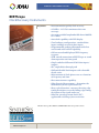
ACTERNA TEST & MEASUREMENT SOLUTIONS
BERTScope
Clock Recovery Instruments
Key Features
■ Instrumentation quality clock recovery
■ 150 Mb/s–12.5 Gb/s continuous data rate
coverage
■ Accurate variable loop bandwidth from 100 kHz
to 12 MHz
■ Auto lock capability with LED display
■ Two hardware configurations, standard data
inputs and high sensitivity data inputs
■ Programmable peaking adjustment with first
and second order roll off capability
■ Self-measured and displayed PLL frequency
response
■ USB control connection to BERTScope or stand
alone operation via front panel
■ Single-ended or differential 50 Ω data inputs/
outputs
■ DC coupled data through path
■ Full and divided clock outputs with selectable
divide ratios
■ Measurement of clock phase error as a function
of frequency and time
■ Data measurement capability
■ Edge Density Measurement — determine the
mark density of the signal under test
■ Duty cycle distortion—measure the rising edge
timing deviations versus the falling edge timing
deviations of the signal under test
■ Ideal for spread spectrum clock (SSC)
applications with large jitter excursions
The vision of a scope, the confidence of a BERT with clock recovery you can count on.
WEBSITE: www.jdsu.com
BERTScope Clock Recovery Instruments
2
Compliant Clock Recovery
Many communication standards now specify
that jitter testing must be carried out using a
reference clock that has been derived from the
data signal. Typical phase lock loop (PLL) characteristics are specified in terms of the -3 dB
bandwidth of the recovery loop, the rate of rolloff of the frequency response, and the degree of
response peaking allowable.
The BERTScope CR and BERTScope CR HS
advanced architectures measure and display
the PLL frequency response from 100 kHz to
12MHz; the widest loop bandwidth available
for jitter testing on the market today. The first
clock recovery instruments to allow full control
of parameters including loop bandwidth, peaking/damping and roll off.
Design and test engineers can now find and
lock onto signals of undefined or unknown
data rate. The engineer can recover full rate
clocks, including spread spectrum clocks, for
signals at data rates from 150Mbps to 12.5 Gb/s.
The engineer has full control of key parameters
for variable loop bandwidth, peaking/damping
and 1st and 2nd order roll offs, optimizing jitter
tracking.
GOLDEN PLL
Many test standards require the use of a Golden
PLL (phase lock loop.) Control of the BERTScope CR and CR HS variable loop bandwidth
allows for control of the jitter transferred to the
recovered clock. When the loop bandwidth
setting is narrow, much of the high frequency
jitter is removed from the clock signal. The
narrowest LBW setting is desirable when an
un-jittered clock is required. When the loop
bandwidth setting is wide, jitter is transferred
to the recovered clock, emulating a clock signal
similar to the CDR of the receiver under test.
Each standard provides an optimum LBW setting for clock recovery often called the Golden
PLL.
Recover Clocks for Optical Storage,
Enterprise and Telecom Testing
The BERTScope CR and BERTScope CR HS
have been designed from the ground up to
provide users with flexibility and accuracy in
compliance measurements. The HS model utilizes high sensitivity data inputs (40 mV single
ended, 20 mV differential) with regenerated
data outputs. It is ideal for optical test applications, like 4X/8X Fibre Channel and 10G
Ethernet standards, where the signal under test
must be split off and converted from electrical
to optical before fed into the clock recovery data
input. The BERTScope CR and CR HS recover
a full rate clock up to 12.5 Gb/s, an important
requirement for testing XFP and other 10 Gb/s
MSA modules. The BERTScope CR HS configuration is also the model of choice in electrical
applications where the additional data input
sensitivity is critical to the test set-up.
Recover Spread Spectrum Clocks for
Testing to Electrical Serial Bus Standards
Spread Spectrum Clocking (SSC) is an increasingly required feature of serial bus standards.
When employed, it can prove difficult to track
but its effect must be included in test. These
instruments able to track SSC correctly with
large jitter excursions up to 5000 ppm, making
it unique amongst clock recovery test solutions.
The BERTScope CR and CR HS are the first
clock recovery instruments to recover clocks
from spread spectrum clocked signals used in
Serial ATA, SAS, PCI Express and FB DIMM
applications.
BERTScope Clock Recovery Instruments
3
User Interface
The instruments can be used with the BERTScope S Stress Analyzer AND in stand alone
operation. Inexperienced users and experts
alike will respond to the same ease and accuracy already available in the BERTScope S
Signal Integrity Analyzer. Perfect companions
to the BERTScope, the clock recovery instruments smoothly integrate with the analyzer,
seamlessly sharing a common user interface.
A single USB connection and supplied high
quality microwave coax cables connect the two
units together - that’s all that is required to start
measurements. The BERTScope automatically senses the presence of the Clock Recovery
instrument, and control is achieved through
the Clock Recovery setup screen. It’s that simple. Additional information is also immediately
available on the front panel display, showing
parameters such as the PLL bandwidth, lock
status, bit rate, peaking and roll-off. The system
is designed to make sure that you are always
aware of the test conditions, always aware of
the factors in play that will affect your measurement results.
Graphing capability allows the user to plot the
loop response and the inverse response curves
with 20 dB and 40 dB plot lines and 3 dB point.
Cursors are available for marking X-Y axis on
each graph. (Future firmware upgrade).
For engineers wanting to utilize test equipment already available on their lab bench, the
BERTScope CR and CR HS are controllable
via the front panel for stand alone operation. In
keeping with the BERTScope family’s philosophy of being the easiest to use signal integrity
tools available, the clock recovery instruments
provide the information you most need immediately available.
An instrument front panel display gives critical
information on the measurement being made,
and settings can also be managed through the
knob and 4 buttons located below the display,
along with a lock button and LED indicator.
This combination ensures that you are never
lost, always certain whether the measurement
you are making includes the effects of clock
recovery.
Duty Cycle Distortion—BERTScope CR
and BERTScope CR
HS are the only clock recovery instruments that
can measure the rising edge timing deviations
versus the falling edge timing deviations to
determine the duty cycle distortion of a signal
under test. This output parameter is available
via front panel and BERTScope user interface.
Clock Out and Sub-rate
Clock Out Both clock recovery instruments
offer full rate clock out to 12.5 Gb/s and sub
rate clock out at all the popular divide ratios
(see listing on page 6.)
BERTScope Clock Recovery Instruments
4
For easy verification of compliance, the correct characteristics are automatically set when
a given standard is selected from a pull-down
menu. However, for users wanting to explore
the limits of their designs, full control of parameters is also easily available. A good example of
this is for systems where restricting the build
up of jitter is critical. Clock recovery plays a
crucial role in this, and the ability to emulate a
clock recovery source with excessive peaking is
a great way of understanding the system sensitivity to jitter gain.
Each instrument has variable jitter peaking
that goes way beyond simple compliance, and
allows jitter gain in excess of 10 dB if desired.
Remote control of the instrument is easily
accessible via USB through BERTScope or via
laptop PC. TCP/IP and GP-IB protocol interfaces are supported.
• Edge Density The user has the ability to
adjust the desired LBW to the edge density
of the signal under test. The edge density
in monitored and then optimized through
loop gain settings. The clock recovery locks
on data patterns with 10% to 100% edge
densities.
• Primary Input Parameters nominal frequency of the data input signal, loop bandwidth,
and peaking (up to 6 dB) are configurable
on the front panel display.
• Lock modes Manual and auto modes are
supported. Locking status is displayed as
locked—LED green, locking—LED amber,
unable to lock—LED red. Lock range, min
10MHz, max 500MHz
• Phase Error The clock extraction circuit
produces a phase error proportional to the
frequency deviation.
The phase error deviation is displayed in %
peak-peak and %RMS, with 10% min–90%
max available range.
• Standards 24 industry standards have been
pre-programmed into the clock recovery
firmware, available via the front panel
interface. Custom settings can also be programmed and saved for future use.
BERTScope Clock Recovery Instruments
5
Standards Coverage
The small graphics and accompanying table show common standards, the data rates they
employ, and the loop bandwidths required for compliance measurements. The clock recovery
instruments encompass a class-leading majority of the common standards, including those
listed in the table and displayed in the graphs.
This ensures that your current and future needs will be covered for compliance and beyond.
Notes:
1. Ripple at high loop bandwidths in these graphs are a feature of the measurement system rather than the loop.
2. The reference (dotted) lines are placed in identical positions in each graph to aid comparison.
BERTScope Clock Recovery Instruments
6
Specifications
Standard
Ethernet
Fibre
Channel
10 Gb/s Ethernet
transmitter test
XAUI
1X
2X
4X
8X
6+ Gb/s
Common
Data rate
Loop band- Peaking
clock divide
(Gb/s)
width (MHz)
(dB)
ratios
10.312
<4
3.125
1.063
2.12
4.25
8.65
4.976 to
6.375
1.875
0.638
1.2756
2.550
5.100
3.6
(fbaud/1667)
8, ITU
6 (fbaud/1677)
other
3.000
10
20
40
80?
OIF CEI
11+ Gb/s
9.95 to 11.1
250UI
Gen 1
fbaud/1667
15
1.5
0.900
5UI
150.000
fbaud/500
6.000
fbaud/1667
1.800
Slope
Spread spectrum
clocking
-20 dB/
decade
No
0.3 max
0.3 max
0.3 max
0.3 max
-20 dB/
decade
No
0.1 max
-20 dB/
decade
No
8 MHz foremost tests for ITU applications, BW1667 other. Minimum of
4 MHz for stress testing in one case.
2.09 - 1.25
dB*
Type 2
Yes, for SATA. Optional
for SAS
Gen 1 & 2 categories:
‘i’ (internal, hard drives etc.) and
‘m’ (medium reach) use fbaud/500
and fbaud/10 for Gen 2 and 250UI
and 65UI for Genb 1.
‘x’ (extended reach) uses fbaud/1667,
Type 2. This is same as SAS.
* Implied: spec’d as damping factor
of 0.707 min to 1.00 max – conversion taken from Gardner (reference
[1]).
+ Loops bandwidths spec’d with
transition density of 1 (100% or
1010101 pattern). Only standard
we’re aware of to specify this.
Assumption is that loop bandwidth
will change proportionally as transition density reduces.
2.09 - 1.25
dB*
2.09 - 1.25
dB*
Type 2
Type 2
SATA (see
note +)
Gen 2
3
30
fbaud/10
SONET/
SDH
XFP/XFI
OC12/STM-4
OC48/STM-16
OC192/STM-64
Receiver
test
XFP/XFI Transmitter
test
SAS
0.622
2.488
9.95
9.95 - 11.2
2.09 - 1.25
dB*
0.250
1.000
4.000
8.000
0.1 max
4.000
0.1 max
24
24
11 to 33
11 to 22
4.8, 6.4, 8.0,
9.6
Forwarded
clock
11 to 22
I
2.5
25
1.500
II
5
50
Gen 1
fbaud/1667
1.5
15
5 to 16
8 to 16
0.900
Gen 2
fbaud/1667
3
30
1.800
Type 2
-20 dB/
decade
64
3.2, 4.0
4.8
FB-DIMM1
Fully
buffered
FB-DIMM2
DIMM
PCI
express
300.000
-20 dB/
decade
Notes
No
No
Yes.
– Transmitter test: Full
2nd order SSC swing
0.5 to 2
– Receiver test: 0.06 UI
swing
1st order
with -20 Yes, optional.
dB/decade – Receiver test: 65 ps
Up to 1 dB 1st or 2nd pk-pk swing
Up to 3 dB
order
0.5 to 3
1st order
(single
pole)
* Implied: spec’d as damping factor
of 0.707 min to 1.00 max – conversion taken from Gardner (reference
[1]).
+ Loops bandwidths spec’d with
transition density of 1 (100% or
1010101 pattern). Only standard
we’re aware of to specify this.
Assumption is that loop bandwidth
will change proportionally as transition density reduces.
BERTScope Clock Recovery Instruments
7
Instrument specifications
Data input
Data interfaces
50 Ω differential or single-ended, DC-coupled. APC 3.5 user-replaceable Planar Crown® adapters.
Data rate coverage
150 Mb/s to 12.5 Gb/s
Data insertion loss
D 1.2 dB (typical)
Data input voltage
-5 Vmin, +5 Vmax
High sensitivity data input
voltage
-5 Vmin, +5 Vmax, 3 Vpeak-peak
Input sensitivity
100 mV single ended (typical)
50 mV differential (typical)
High sensitivity configuration
40 mV single ended (typical)
20 mV differential (typical)
Data output
Phase error out
10% minimum, 90% maximum
Edge density
10% minimum, 100% maximum
Clock
Clock interfaces
50 Ω single-ended, AC Coupled. APC 3.5 user-replaceable Planar
Crown® adapter
Clock output range
150 MHz to 12.5 GHz (full rate clock output)
Loop bandwidth
100 kHz–12 MHz variable
Frequency response roll-off
-20 dB/ decade and -40 dB/ decade
Intrinsic jitter
250fsec RMS
Output frequency deviation
+500/-5500 ppm (+0.05/-0.55%)
(tracking 30 to 33 kHz sawtooth
modulated SSC)
Clock and sub-rate clock output 250 mV minimum, 1.5 V maximum
amplitude
Divided clock output
Full rate divided by 1, 2, 4, 5, 6, 7, 8, 9, 10, 12, 14, 16, 18, 20, 24, 25,
28, 30, 32, 35, 36, 40, 42, 45, 48, 49, 50, 54, 56, 60, 63, 64, 70, 72, 80,
81, 90, 100, 108, 112, 120, 126, 128, 140, 144, 160, 162, 168, 180,
192, 196, 200, 216, 224, 240, 252, 256, 280, 288, 320, 324, 336, 360,
384, 392, 432, 448, 504, 512, 576, 648
Divided Clock Interface
SMA
Device info
Serial number, revision codes available via front panel display
Communication
USB cable (supplied). Unit also provides hub capability giving 3
additional USB ports.
Ordering Information
Ordering number and prices on request.
The BERTScope CR and CR HS come standard with USB cable, US power cord, clock and data
cables for use with BERTScope S, SMA terminations for data outputs, software on CD ROM, and
User’s Manual for stand alone use.
BERTScope Clock Recovery Instruments
About BERTScopeTM
BERTScopeTM is a registered trademark of SyntheSys Research, Inc., a
privately held California corporation founded in 1989 with the mission
to develop advanced test instruments for identifying and locating the
source of errors in high-speed digital bit streams. BERTScope CR pairs
with BERTScope to offer the vision of a scope, the confidence of a BERT,
and clock recovery you can count on.
More information is available at www.bertscope.com.
All statements, technical information and recommendations related to the products herein are based upon information believed to be reliable or accurate. However, the accuracy or completeness thereof is not guaranteed, and
no responsibility is assumed for any inaccuracies. The user assumes all risks and liability whatsoever in connection with the use of a product or its applications. JDSU reserves the right to change at any time without notice
the design, specifications, function, fit or form of its products described herein, including withdrawal at any
time of a product offered for sale herein. JDSU makes no representations that the products herein are free from
any intellectual property claims of others. Please contact JDSU for more information. JDSU and the JDSU logo
are trademarks of JDS Uniphase Corporation. Other trademarks are the property of their respective holders.
© 2006 JDS Uniphase Corporation. All rights reserved. 30137432 500 0206 BERTSCOPE.DS.CPO.TM.AE
Test & Measurement Regional Sales
NORTH AMERICA
LATIN AMERICA
ASIA PACIFIC
TEL: 1 866 228 3762
FAX: +1 301 353 9216
TEL:+55 11 5503 3800
FAX:+55 11 5505 1598
TEL:+852 2892 0990
FAX:+852 2892 0770
EMEA
TEL:+49 7121 86 2222
FAX:+49 7121 86 1222
WEBSITE: www.jdsu.com