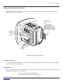
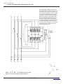
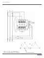
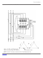
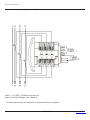
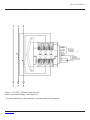
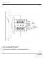
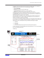
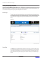
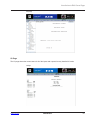
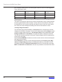
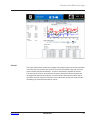
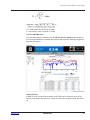
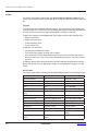
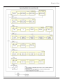
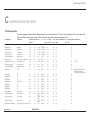
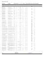
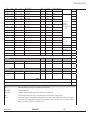
1
PXM 2000 Series (PXM 2250/2260/2270) Multifunction Electricity Meter with Ethernet Communication User & Installation Manual IM02601001E Rev. 1.1 www.eaton.com Copyright © 2009 by Eaton Corporation. All rights reserved. Eaton, Power Xpert, PowerChain Management, Powerware, and X-Slot are registered trademarks of Eaton Corporation or its subsidiaries and affiliates. Microsoft and Windows are registered trademarks of Microsoft Corporation. Modbus is a registered trademark of Schneider Electric. EATON CORPORATION - CONFIDENTIAL AND PROPRIETARY NOTICE TO PERSONS RECEIVING THIS DOCUMENT AND/OR TECHNICAL INFORMATION THIS DOCUMENT, INCLUDING THE DRAWING AND INFORMATION CONTAINED THEREON, IS CONFIDENTIAL AND IS THE EXCLUSIVE PROPERTY OF EATON CORPORATION, AND IS MERELY ON LOAN AND SUBJECT TO RECALL BY EATON AT ANY TIME. BY TAKING POSSESSION OF THIS DOCUMENT, THE RECIPIENT ACKNOWLEDGES AND AGREES THAT THIS DOCUMENT CANNOT BE USED IN ANY MANNER ADVERSE TO THE INTERESTS OF EATON, AND THAT NO PORTION OF THIS DOCUMENT MAY BE COPIED OR OTHERWISE REPRODUCED WITHOUT THE PRIOR WRITTEN CONSENT OF EATON. IN THE CASE OF CONFLICTING CONTRACTUAL PROVISIONS, THIS NOTICE SHALL GOVERN THE STATUS OF THIS DOCUMENT. DISCLAIMER OF WARRANTIES AND LIMITATION OF LIABILITY The information, recommendations, descriptions and safety notations in this document are based on Eaton Electrical Inc. and/or Eaton Corporation’s (“Eaton”) experience and judgment and may not cover all contingencies. If further information is required, an Eaton sales office should be consulted. Sale of the product shown in this literature is subject to the terms and conditions outlined in appropriate Eaton selling policies or other contractual agreement between Eaton and the purchaser. THERE ARE NO UNDERSTANDINGS, AGREEMENTS, WARRANTIES, EXPRESSED OR IMPLIED, INCLUDING WARRANTIES OF FITNESS FOR A PARTICULAR PURPOSE OR MERCHANTABILITY, OTHER THAN THOSE SPECIFICALLY SET OUT IN ANY EXISTING CONTRACT BETWEEN THE PARTIES. ANY SUCH CONTRACT STATES THE ENTIRE OBLIGATION OF EATON. THE CONTENTS OF THIS DOCUMENT SHALL NOT BECOME PART OF OR MODIFY ANY CONTRACT BETWEEN THE PARTIES. In no event will Eaton be responsible to the purchaser or user in contract, in tort (including negligence), strict liability or otherwise for any special, indirect, incidental or consequential damage or loss whatsoever, including but not limited to damage or loss of use of equipment, plant or power system, cost of capital, loss of power, additional expenses in the use of existing power facilities, or claims against the purchaser or user by its customers resulting from the use of the information, recommendations and descriptions contained herein. Product Registration PLEASE REGISTER YOUR PRODUCT By registering your product you’re registering for the warranty in addition to receiving important update information. You can register your product in one of three ways: 1. Go online to: www.eaton.com/powerxpert and click on Product Registration under Related Links 2. Fill out and return the product registration card that can be found in the packet of information you received. 3. Fill out the product registration information below and fax this page to 919-431-6240 Product:__________________________________________________________ Product Model or Version Number:_____________________________________ Product Serial or License Number:_____________________________________ Company:________________________________________________________ Your Name:_______________________________________________________ Address:_________________________________________________________ Address:_________________________________________________________ City:_________________________________ State:________ Zip:_______ Email:___________________________________________________________ Today’s Date:_____________________________________________________ Phone:___________________________________________________________ Eaton GO number (if known)_________________________________________ Table of Contents 1 Introduction..............................................................................................................................................................................1-1 About This Manual......................................................................................................................................................................1-1 Warranty and Liability Information..............................................................................................................................................1-1 Safety Precautions.....................................................................................................................................................................1-2 2 Overview and Specifications..................................................................................................................................................2-1 Power Xpert Meter 2000 Series Overview.................................................................................................................................2-1 Voltage and Current Inputs.........................................................................................................................................................2-2 Ordering Information..................................................................................................................................................................2-3 Measured Values........................................................................................................................................................................2-4 Utility Peak Demand...................................................................................................................................................................2-5 Compliance................................................................................................................................................................................2-8 Accuracy (See full Range specifications earlier in this chapter.)............................................................................ 2-8 3 Mechanical Installation...........................................................................................................................................................3-1 Introduction.................................................................................................................................................................................3-1 ANSI Installation Steps...............................................................................................................................................................3-3 DIN Installation Steps ................................................................................................................................................................3-4 PXM 2000 Series Transducer Installation..................................................................................................................................3-5 4 Electrical Installation...............................................................................................................................................................4-1 Considerations When Installing Meters......................................................................................................................................4-1 CT Leads Pass Through (No Meter Termination)......................................................................................................................4-3 Voltage and Power Supply Connections....................................................................................................................................4-5 Ground Connections..................................................................................................................................................................4-5 Voltage Fuses.............................................................................................................................................................................4-5 5 Serial Communication Installation.........................................................................................................................................5-1 PXM 2000 Series Communication.............................................................................................................................................5-1 RS485 / KYZ Output (Com 2)....................................................................................................................................................5-1 PXM 2000 Series Transducer Communication Information.......................................................................................................5-4 6 Using the PXM 2000 Series.....................................................................................................................................................6-1 Introduction.................................................................................................................................................................................6-1 Understanding Meter Face Elements.........................................................................................................................................6-1 Understanding Meter Face Buttons............................................................................................................................................6-1 Using the Front Panel . ..............................................................................................................................................................6-2 Understanding Startup and Default Displays.............................................................................................................................6-2 Using the Main Menu ................................................................................................................................................................6-3 Using Reset Mode .....................................................................................................................................................................6-3 Entering a Password .................................................................................................................................................................6-4 Using Configuration Mode..........................................................................................................................................................6-5 Configuring the Scroll Feature....................................................................................................................................................6-6 Configuring CT Setting...............................................................................................................................................................6-7 Configuring PT Setting...............................................................................................................................................................6-8 Configuring Connection Setting..................................................................................................................................................6-9 Configuring Communication Port Setting...................................................................................................................................6-9 Using Operating Mode.............................................................................................................................................................6-10 Understanding the % of Load Bar............................................................................................................................................6-11 Performing Watt-Hour Accuracy Testing (Verification)..............................................................................................................6-12 www.eaton.com IM02601001E TOC- 1 7 Using the I/O Option Cards.....................................................................................................................................................7-1 Overview.....................................................................................................................................................................................7-1 Installing an Option Card............................................................................................................................................................7-1 Configuring Option Cards ..........................................................................................................................................................7-2 Digital Output (Relay Contact) / Digital Input Card (-1)..............................................................................................................7-3 Pulse Output (Solid State Relay Contacts) / Digital Input Card (-2)...........................................................................................7-5 1mA Output Card (-3).................................................................................................................................................................7-7 20mA Output Card (-4)...............................................................................................................................................................7-9 Network Communications with the Power Xpert® 2000 Series (-5)................................................................................. 7-11 Using the PXM 2000 Gateway Card........................................................................................................................................7-12 8 Introduction to Web Server Pages.........................................................................................................................................8-1 Accessing the Web Pages..........................................................................................................................................................8-1 Home Page (Default)..................................................................................................................................................................8-2 Common Controls for Selecting Information..............................................................................................................................8-2 Printing and Exporting Information.............................................................................................................................................8-4 Events Page...............................................................................................................................................................................8-4 Setup Page.................................................................................................................................................................................8-4 I/O Page.....................................................................................................................................................................................8-5 Help Page . ................................................................................................................................................................................8-6 9 Functions on the Web Server Pages......................................................................................................................................9-1 Overview.....................................................................................................................................................................................9-1 Current........................................................................................................................................................................................9-3 Power.........................................................................................................................................................................................9-5 Quality........................................................................................................................................................................................9-6 Energy........................................................................................................................................................................................9-8 Events......................................................................................................................................................................................9-12 10 Setup on the Web Server Pages . ......................................................................................................................................10-1 Overview...................................................................................................................................................................................10-1 Alarm Triggers..........................................................................................................................................................................10-4 Meter Setup & Commissioning.................................................................................................................................................10-7 Option Cards ........................................................................................................................................................................10-12 System Setup ........................................................................................................................................................................10-18 Diagnostics.............................................................................................................................................................................10-20 11 Root Certificate Authority Installation...............................................................................................................................11-1 Installing Root CA with Microsoft Internet Explorer 6..............................................................................................................11-1 Installing Root CA with Microsoft Internet Explorer 7...............................................................................................................11-6 A Navigation Maps..................................................................................................................................................................... A-1 Introduction................................................................................................................................................................................ A-1 Navigation Maps (Sheets 1 to 4)............................................................................................................................................... A-1 Main Menu Screens (Sheet 1)........................................................................................................................................... A-2 Operating Mode Screens (Sheet 2)........................................................................................................................................... A-3 Reset Mode Screens (Sheet 3)................................................................................................................................................. A-4 B DIP Switch Description.......................................................................................................................................................... B-1 C Modbus Register Maps.......................................................................................................................................................... C-1 TCP/IP Register Map................................................................................................................................................................. C-1 1 mA Output Card Register Map............................................................................................................................................... C-8 4-20 mA Output Card Map...................................................................................................................................................... C-11 Pulse Output (Solid State Relay Contacts) / Digital Input Card Map....................................................................................... C-15 Digital Output (Relay Contact) / Digital Input Card Map.......................................................................................................... C-18 RTU (RS485) Map................................................................................................................................................................... C-28 TOC-2 IM02601001E www.eaton.com Introduction 1 Introduction About This Manual This document is the user manual for the installation, operation, and maintenance of the Eaton Power Xpert® Meter 2000 Series. It is intended for authorized and qualified personnel who use the PXM 2250/2260/2270 meters. Please refer to the specific WARNINGS and CAUTIONS in this section before proceeding. For Technical Support and after hour emergencies, contact our Power Quality Technical Support team at 1-800-809-2772, option 4 / sub-option 1 or by email at [email protected]. For those outside the United States and Canada, call 414-449-7100 option 4 / sub-option 1. You can also visit us on the web at http://www.eaton.com and follow the Products link. Warranty and Liability Information NO WARRANTIES EXPRESSED OR IMPLIED, INCLUDING WARRANTIES OF FITNESS FOR A PARTICULAR PURPOSE OF MERCHANTABILITY, OR WARRANTIES ARISING FROM COURSE OR DEALING OR USAGE OF TRADE ARE MADE REGARDING THE INFORMATION, RECOMMENDATIONS, AND DESCRIPTIONS CONTAINED HEREIN. In no event will Eaton be responsible to the purchaser or user in contract, in tort (including negligence), strict liability or otherwise for any special, indirect, incidental, or consequential damage or loss of use of equipment, plant or power system, cost of capital, loss of power, additional expenses in the use of existing power facilities, or claims against the purchaser or user by its customers resulting from the use of the information and descriptions contained herein. Eaton disclaims liability for any modifications or interfaces with other equipment that are not in conformity with the specifications and information contained within this manual. Any unauthorized action of this kind can jeopardize operation, safety, or reliability. The information contained in this document is believed to be accurate at the time of publication, however, Eaton assumes no responsibility for any errors which may appear here and reserves the right to make changes without notice. www.eaton.com IM02601001E 1-1 Introduction Safety Precautions All safety codes, safety standards, and/or regulations must be strictly observed in the installation, operation, and maintenance of this device. WARNINGS refer to instructions that, if not followed, can result in death or injury. CAUTIONS refer to instructions that, if not followed, can result in equipment damage. WARNINGS SHOCK HAZARDS: IMPROPER INSTALLATION CAN CAUSE DEATH, INJURY, AND/OR EQUIPMENT DAMAGE. Follow all Warnings and Cautions. Completely read and understood the information in this document before attempting to install or operate the equipment. Improper wiring could cause death, injury, or equipment damage. Only qualified personnel are to service the PXM 2000 Series. TROUBLESHOOTING PROCEDURES MAY REQUIRE PROXIMITY TO EXPOSED ENERGIZED (LIVE) ELECTRICAL WIRING AND/OR PARTS WHERE THE HAZARD OF FATAL ELECTRIC SHOCK IS PRESENT. Exercise extreme care to avoid injury or death. Always disconnect, lock-out, and tag the current and voltage sources and the control power supply circuit before touching the connections or components on the rear face of the meter base unit. FAILURE TO GROUND THE PXM 2250/2260/2270 METER MAY RESULT IN INJURY, DEATH, OR EQUIPMENT DAMAGE. Properly ground the meter during installation. 2 Covered by one or more of the following patents: US Patent Numbers D526920, D525893, 6751563, 6735535, 6636030. IM02601001E www.eaton.com Overview and Specifications 2 Overview and Specifications Power Xpert Meter 2000 Series Overview The PXM 2250/2260/2270 is a multifunction power and energy meter designed to be used in electrical substations, panel boards, and as a primary revenue meter, due to its high performance measurement capability. The unit provides multifunction measurement of all electrical parameters and makes the data available in multiple formats via display, communication systems, and through analog signal transmission. Figure 2.1: PXM 2000 Meter The PXM 2000 Series meter is designed with advanced meaurement capabilities, allowing it to achieve high performance accuracy. It is specified as a 0.2% class energy meter for billing applications as well as a highly accurate panel indication meter. The PXM 2000 Series meter provides additional capabilities, including standard RS485, Ethernet capability, Modbus and DNP 3.0Protocols, and Option cards that can be added at any time. Features of the PXM 2000 Series include: • 0.2% Class revenue certifiable energy and demand metering • Meets ANSI C12.20 (0.2%) and IEC 687 (0.2%) classes • Multifunction measurement including voltage, current, power, frequency, energy, power factor, etc. • Power quality measurements (%THD and Alarm Limits) • Percentage of Load Bar for analog meter reading • Easy to use faceplate programming • Standard RS485 communication • Standard Ethernet communication • Optional I/O Cards - field upgradeable without removing installed meter In addition to the PXM 2000 Series meter with integral display/transducer configuration, a transducer-only (without a display) configuration is available. The PXM 2000 Series Transducer provides RS485 communication via Modbus RTU, Modbus ASCII or DNP 3.0 protocols, as well as standard Ethernet communication. 2-1 IM02601001E www.eaton.com Overview and Specifications Voltage and Current Inputs Universal Voltage Inputs Voltage Inputs allow measurement up to 576VAC (Phase to Reference) and 721VAC (Phase to Phase). This insures proper meter safety when wiring directly to high voltage systems. One unit will perform to specification on 69 Volt, 120 Volt, 230 Volt, 277 Volt, and 347 Volt power systems. NOTE: Higher voltages require the use of potential transformers (PTs). Current Inputs The unit supports a 5 amp or a 1 amp secondary for current measurements. NOTE: The secondary current must be specified and ordered with the meter. The PXM 2000 Series Current Inputs use a unique dual input method: Method 1: CT Pass Through The CT passes directly through the meter without any physical termination on the meter. This insures that the meter cannot be a point of failure on the CT circuit. This is preferable for utility users when sharing relay class CTs. No Burden is added to the secondary CT circuit. Method 2: Current “Gills” This unit additionally provides ultra-rugged Termination Pass Through Bars that allow CT leads to be terminated on the meter. This eliminates any possible point of failure at the meter. This is a preferred technique for insuring that relay class CT integrity is not compromised (the CT will not open in a fault condition). 2-2 IM02601001E www.eaton.com Overview and Specifications Ordering Information PXM -2260 -M - A - 6 - 5 - 1 - 1 - 5 1 2 3 4 5 6 7 1. Model: 2250 = Power Meter 2260 = Power Quality Meter 2270 = Power Quality Plus Meter 2. Meter Type M = Meter (with integral display) T = Transducer Only (no display) 3. Frequency: 5 = 50 Hz System 6 = 60 Hz System 4. Current Input: 5 = 5 Amp Secondary 1 = 1 Amp Secondary 5. Power Supply: 1 = Universal, (90 - 265) VAC @50/60Hz or (100-370) VDC 4 = (18 - 60) VDC 6. I/O Slot 1: (See Chapter 7 for I/O Card Specifications.) 0 = None 1 = 2 Relay Outputs/2 Status Inputs 2 = 4 KYZ Pulses/4 Status Inputs 3 = 4 Analog Outputs - 0-1 mA 4 = 4 Analog Outputs - 4-20 mA 7. I/O 2: (See Chapter 7 for I/O Card Specifications.) 5 = Power Xpert® Ethernet Gateway Card Example: PXM 2260-M-A-6-5-1-1-5 (PXM 2260 Meter with 60 Hz System, 5 Amp Secondary, 90-265 VAC/100-370 VDC Power Supply, 2 Relay Outputs/2 Status Inputs I/O Card in Card Slot 1 and standard Power Xpert® Ethernet Gateway Card in Card Slot 2) 2-3 IM02601001E www.eaton.com Overview and Specifications Measured Values The PXM 2000 Series provides the following Measured Values all in Real-Time Instantaneous, and some additionally as Average, Maximum and Minimum values. 2-4 PXM 2000 Series Measured Values Measured Values Instantaneous Voltage L-N X Avg Max Min X X Voltage L-L X X X Current per Phase X X X X Current Neutral X X X X WATT(A,B,C,Tot.) X X X X VAR (A,B,C,Tot.) X X X X VA (A,B,C,Tot.) X X X X PF (A,B,C,Tot.) X X X X +Watt-Hour (A,B,C,Tot.) X -Watt-Hour (A,B,C,Tot.) X Watt-Hour Net X +VAR-Hour (A,B,C,Tot.) X -VAR-Hour (A,B,C,Tot.) X VAR-Hour Net (A,B,C,Tot.) X VA-Hour (A,B,C,Tot.) X Frequency X X X X X %THD X Voltage Angles X Current Angles X % of Load Bar X IM02601001E www.eaton.com Overview and Specifications Utility Peak Demand The PXM 2000 Series provides user-configured Fixed Window or Sliding Window Demand modes. This feature enables you to set up a customized Demand profile. Fixed Window Demand mode records the average demand for time intervals that you define (usually 5, 15 or 30 minutes). Sliding Window Demand mode functions like multiple, overlapping Fixed Window Demands. You define the subintervals at which an average of demand is calculated. An example of Sliding Window Demand mode would be a 15-minute Demand block using 5-minute subintervals, thus providing a new demand reading every 5 minutes, based on the last 15 minutes. Utility Demand Features can be used to calculate Watt, VAR, VA and PF readings. Voltage provides an Instantaneous Max and Min reading which displays the highest surge and lowest sag seen by the meter. All other parameters offer Max and Min capability averaged over the demand period (meter) or true Min and Max (Gateway Card).. Specifications Power Supply Range: Power Consumption: 1 Option: Universal, (90 - 265)VAC @50/60 Hz or (100-370)VDC 4 Option: (18 - 60)VDC (5 to 10)VA, (3.5 to 7)W - depending on the meter’s hardware configuration Voltage Inputs (Measurement Category III) (See Accuracy Specifications, later in this chapter. Range: Supported hookups: Input Impedance: Burden: Pickup Voltage: Connection: Fault Withstand: Reading: Universal, Auto-ranging: Phase to Reference (Va, Vb, Vc to Vref): (20 to 576)VAC Phase to Phase (Va to Vb, Vb to Vc, Vc to Va): (0 to 721)VAC 3 Element Wye, 2.5 Element Wye, 2 Element Delta, 4 Wire Delta 1M Ohm/Phase 0.36VA/Phase Max at 600 Volts; 0.014VA at 120 Volts 20VAC 7 Pin 0.400” Pluggable Terminal Block AWG#12 -26/ (0.129 -3.31) mm2 Meets IEEE C37.90.1 Programmable Full Scale to any PT Ratio Current Inputs(See Accuracy Specifications, later in this chapter.) 2-5 Class 10: Class 2: Burden: Pickup Current: 5A Nominal, 10A Maximum 1A Nominal, 2A Maximum 0.005VA Per Phase Max at 11 Amps 0.1% of nominal Connections: O Lug or U Lug Electrical Connection (Diagram 4.1) Pass-through Wire, 0.177” / 4.5mm Maximum Diameter (Diagram 4.2) Quick Connect, 0.25” Male Tab (Diagram 4.3) 100A/10sec., 300A/3sec., 500A/1sec. Fault Withstand: IM02601001E www.eaton.com Overview and Specifications KYZ/RS485 Port Specifications RS485 Transceiver; meets or exceeds EIA/TIA-485 Standard: Type: Min. Input Impedance: Max. Output Current: Two-wire, half duplex 96kΩ ±60mA Wh Pulse KYZ output contacts (and infrared LED light pulses through face plate): (See Chapter 6 for Kh values.) Pulse Width: 90ms Full Scale Frequency: ~3Hz Contact type: Solid State – SPDT (NO – C – NC) Relay type: Solid state Peak switching voltage: DC ±350V Continuous load current: 120mA Peak load current: 350mA for 10ms On resistance, max.: 35Ω Leakage current: 1µA@350V Isolation: AC 3750V Reset State: (NC - C) Closed; (NO - C) Open Infrared LED: Peak Spectral Wavelength:940nm Reset State: Off Internal Schematic: Output timing: T [s] = NC C 90ms LED OFF LED ON Watthour 3600 ⋅ Kh pulse P[Watt ] IR LED Light Pulses Through face plate LED OFF P[Watt] - Not a scaled value Kh – See Section 6-4 for values 90ms LED OFF LED ON NO KYZ output Contact States Through Backplate (De-energized State) 2-6 NC NC NC NC NC C C C C C NO NO NO NO NO IM02601001E www.eaton.com Overview and Specifications Isolation All Inputs and Outputs are galvanically isolated to 2500 Vac Environmental Rating Storage: Operating: Humidity: Faceplate Rating: (-20 to +70)0 C (-20 to +70)0 C to 95% RH Non-condensing NEMA12 (Water Resistant), Mounting Gasket Included Measurement Methods Voltage, Current: Power: True RMS Sampling at over 400 Samples per Cycle on All Channels Update Rate Watts, VAR and VA: All other parameters: Every 6 cycles (e.g., 100 ms @ 60 Hz) Every 60 cycles (e.g., 1 s @ 60 Hz) 1 second for current only measurement, if reference voltage is not available Communication Serial Communications Format: 1. RS485 Port through Back Plate 2. Energy Pulse Output through Back Plate Protocols: Com Port Baud Rate: Com Port Address: Data Format: PXM 2000 Series Transducer Modbus RTU, Modbus ASCII, DNP 3.0 9,600 to 57,600 bps 001-247 8 Bit, No Parity Default Initial Communication Baud 9600 (See Chapter 5) Network Communications Format: Connection Type: RJ45, 10/100BaseT Ethernet Network Port Protocols: Ethernet TCP/IP, Modbus TCP, HTTP, HTTPS, NTP, SMTP, SNMP Mechanical Parameters Dimensions: see Chapter 3. Weight: 2 pounds/ 0.9kg (ships in a 6”/152.4mm cube container) (Without Option Card) 2-7 IM02601001E www.eaton.com Overview and Specifications Compliance • • • • • I C12.2• UL Listing: USL/CNL E185559 CE (EN61326-1, FCC Part 15, Subpart B, Class A) IEC 687 (0.2% Accuracy) ANSI C12.20 (0.2% Accuracy)• ANSI C62.41 (Burst)• IEC 1000-4-2 - ESD Accuracy (See full Range specifications earlier in this chapter.) For 23o C, 3 Phase balanced Wye or Delta load, at 50 or 60 Hz (as per order), 5A (Class 10) nominal unit: Parameter Voltage L-N [V] 0.1% of reading (69 to 480)V Voltage L-L [V] 0.2% of reading 2 0.1% of reading3 (120 to 600)V Current Neutral (calculated) [A] 2% of Full Scale (0.15 to 5) A @ (45 to 65) Hz Active Power Total [W] 0.2% of reading 1, 2 (0.15 to 5) A @ (69 to 480) V @ +/- (0.5 to 1) lag/lead PF Active Energy Total [Wh] 0.2% of reading 1, 2 (0.15 to 5) A @ (69 to 480) V @ +/- (0.5 to 1) lag/lead PF 0.2% of reading 1, 2 (0.15 to 5) A @ (69 to 480) V @ +/- (0 to 0.8) lag/lead PF 0.2% of reading 1, 2 (0.15 to 5) A @ (69 to 480) V @ +/- (0 to 0.8) lag/lead PF Current Phase [A] Reactive Power Total [VAR] Reactive Energy Total [VARh] (0.15 to 5) A Power Factor 0.2% of reading 1, 2 (0.15 to 5) A @ (69 to 480) V @ +/- (0.5 to 1) lag/lead PF 0.2% of reading 1, 2 (0.15 to 5) A @ (69 to 480) V @ +/- (0.5 to 1) lag/lead PF 0.2% of reading 1, 2 (0.15 to 5) A @ (69 to 480) V @ +/- (0.5 to 1) lag/lead PF Frequency [Hz] +/- 0.03 Hz (45 to 65) Hz Total Harmonic Distortion [%] +/- 2% (0.5 to 10)A4 or (69 to 480)V, measurement range (1 to 99.99)% Load Bar +/- 1 segment (0.005 to 6) A Apparent Power Total [VA] Apparent Energy Total [VAh] Accuracy Input Range1 Accuracy 2-8 1 • For 2.5 element programmed units, degrade accuracy by an additional 0.5% of reading. • For 1A (Class 2) Nominal, degrade accuracy by an additional 0.5% of reading. • For 1A (Class 2) Nominal, the input current range for accuracy specification is 20% of the values listed in the table. 2 For unbalanced voltage inputs where at least one crosses the 150V autoscale threshold (for example, 120V/120V/208V system), degrade the accuracy to 0.4% of reading. 3 With reference voltage applied (VA, VB, or VC). Otherwise, degrade accuracy to 0.2%. See hookup diagrams 8, 9, and 10 in Chapter 4. 4 At least one voltage input (minimum 20 Vac) must be connected for THD measurement on current channels. IM02601001E www.eaton.com Mechanical Installation 3 Mechanical Installation Introduction The PXM 2000 Series can be installed using a standard ANSI C39.1 (4” Round) or an IEC 92mm DIN (Square) form. In new installations, simply use DIN or ANSI punches. For existing panels, pull out old analog meters and replace them with the PXM Series meter. The various models use the same installation. See Chapter 4 for wiring diagrams. NOTE: The drawings shown below and on the next page give you the meter dimensions in inches and millimeters (mm shown in brackets). Tolerance is +/- 0.1” [2.54 mm]. Figure 3.1: Meter Face Figure 3.2: Meter Dimensions 100 100 Act Act 100 Act Figure 3.3: Transducer Dimensions www.eaton.com IM02601001E 3-1 Mechanical Installation 100 Act Fig. 3.4: Meter Back Figure 3.5: ANSI Mounting Panel Cutout Figure 3.6: DIN Mounting Cutout 3-2 IM02601001E www.eaton.com Mechanical Installation ANSI Installation Steps NEMA 12 Mounting Gasket Threaded Rods Lock Washer and Nut Figure 3.7: ANSI Mounting Procedure 1.Insert 4 threaded rods by hand into the back of meter. Twist until secure. 2.Slide NEMA 12 Mounting Gasket onto back of meter with rods in place. 3.Slide meter with Mounting Gasket into panel. 4.Secure from back of panel with lock washer and nut on each threaded rod. Use a small wrench to tighten. Do not overtighten. The maximum installation torque is 0.4 Newton-Meter. www.eaton.com IM02601001E 3-3 Mechanical Installation DIN Installation Steps DIN Mounting Bracket Top Mounting Bracket Groove Bottom Mounting Bracket Groove #8 Screw PXM Series Meter with NEMA 12 Mounting Gasket Remove (unscrew) ANSI Studs for DIN Installation Figure 3.8: DIN Mounting Procedure 1. Slide meter with NEMA 12 Mounting Gasket into panel. (Remove ANSI Studs, if in place.) 2. From back of panel, slide 2 DIN Mounting Brackets into grooves in top and bottom of meter housing. Snap into place. 3. Secure meter to panel with lock washer and a #8 screw through each of the 2 mounting brackets. Tighten with a #2 Phillips screwdriver. Do not overtighten. The maximum installation torque is 0.4 Newton-Meter. 3-4 IM02601001E www.eaton.com Mechanical Installation PXM 2000 Series Transducer Installation The PXM 2000 Series Transducer model is installed using DIN Rail Mounting. Specs for DIN Rail Mounting: DIN Rail (Slotted) Dimensions: International Standards DIN 46277/3 0.297244” x 1.377953” x 3” (inches) 7.55mm x 35mm x 76.2mm (millimeters) Figure 3.9: DIN Rail Mounting Procedure Release Clip 1. Slide top groove of meter onto the DIN Rail. 2. Press gently until the meter clicks into place. NOTES: • To remove the meter from the DIN Rail, pull down on the Release Clip to detach the unit from the rail. • If mounting with the DIN Rail provided, use the Black Rubber Stoppers (also provided). See figure on the right. NOTE ON DIN RAILS: DIN Rails are commonly used as a mounting channel for most terminal blocks, control devices, circuit protection devices and PLCs. DIN Rails are made of cold rolled steel electrolitically plated and are also available in aluminum, PVC, stainless steel and copper. www.eaton.com IM02601001E 3-5 Mechanical Installation 3-6 IM02601001E www.eaton.com Electrical Installation 4 Electrical Installation Considerations When Installing Meters Installation of the PXM 2000 Series must be performed only by qualified personnel who follow standard safety precautions during all procedures. Those personnel should have appropriate training and experience with high voltage devices. Appropriate safety gloves, safety glasses and protective clothing is recommended. During normal operation of the PXM 2000 Series, dangerous voltages flow through many parts of the meter, including: Terminals and any connected CTs (Current Transformers) and PTs (Potential Transformers), all I/O Modules (Inputs and Outputs) and their circuits. All Primary and Secondary circuits can, at times, produce lethal voltages and currents. Avoid contact with any current-carrying surfaces. Do not use the meter or any I/O Output Device for primary protection or in an energy-limiting capacity. The meter can only be used as secondary protection. Do not use the meter for applications where failure of the meter may cause harm or death. Do not use the meter for any application where there may be a risk of fire. All meter terminals should be inaccessible after installation. Do not apply more than the maximum voltage the meter or any attached device can withstand. Refer to meter and/ or device labels and to the Specifications for all devices before applying voltages. Do not HIPOT/Dielectric test any Outputs, Inputs or Communications terminals. Eaton recommends the use of Shorting Blocks and Fuses for voltage leads and power supply to prevent hazardous voltage conditions or damage to CTs, if the meter needs to be removed from service. CT grounding is optional. NOTES: • IF THE EQUIPMENT IS USED IN A MANNER NOT SPECIFIED BY THE MANUFACTURER, THE PROTECTION PROVIDED BY THE EQUIPMENT MAY BE IMPAIRED. • THERE IS NO REQUIRED PREVENTIVE MAINTENANCE OR INSPECTION NECESSARY FOR SAFETY. HOWEVER, ANY REPAIR OR MAINTENANCE SHOULD BE PERFORMED BY THE FACTORY. www.eaton.com DISCONNECT DEVICE: The following part is considered the equipment disconnect device. A SWITCH OR CIRCUIT-BREAKER SHALL BE INCLUDED IN THE END-USE EQUIPMENT OR BUILDING INSTALLATION. THE SWITCH SHALL BE IN CLOSE PROXIMITY TO THE EQUIPMENT AND WITHIN EASY REACH OF THE OPERATOR. THE SWITCH SHALL BE MARKED AS THE DISCONNECTING DEVICE FOR THE EQUIPMENT. IM02601001E 4-1 Electrical Installation CT Leads Terminated to Meter The PXM 2000 Series is designed to have Current Inputs wired in one of three ways. Diagram 4.1 shows the most typical connection where CT Leads are terminated to the meter at the Current Gills. This connection uses NickelPlated Brass Studs (Current Gills) with screws at each end. This connection allows the CT wires to be terminated using either an “O” or a “U” lug. Tighten the screws with a #2 Phillips screwdriver. The maximum installation torque is 1 Newton-Meter. Other current connections are shown in Figures 4.2 and 4.3. Voltage and RS485/KYZ Connection is shown in Figure 4.4. Current Gills (Nickel-Plated Brass Stud) Figure 4.1: CT Leads terminated to Meter, #8 Screw for Lug Connection Wiring Diagrams are shown later in this chapter. Communications Connections are detailed in Chapter 5. 4-2 IM02601001E www.eaton.com Electrical Installation CT Leads Pass Through (No Meter Termination) The second method allows the CT wires to pass through the CT Inputs without terminating at the meter. In this case, remove the Current Gills and place the CT wire directly through the CT opening. The opening will accomodate up to 0.177” / 4.5mm maximum diameter CT wire. CT Wire passing through meter Current Gills removed Figure 4.2: Pass-Through Wire Electrical Connection www.eaton.com IM02601001E 4-3 Electrical Installation Quick Connect Crimp-on Terminations For Quick Termination or for Portable Applications, a 0.25” Quick Connect Crimp-on Connectors can also be used. Quick Connect Crimp-on Terminations Figure 4.3: Quick Connect Electrical Connection 4-4 IM02601001E www.eaton.com Electrical Installation Voltage and Power Supply Connections Voltage Inputs are connected to the back of the unit via a optional wire connectors. The connectors accomodate AWG# 12 -26/ (0.129 - 3.31)mm2. RS485 and KYZ Pulse Output CAUTION! Do not apply input or supply voltage to these Power Supply Inputs Voltage Inputs Figure 4.4: Voltage Connection Ground Connections The meter’s Ground Terminals should be connected directly to the installation’s protective earth ground. Use AWG# 12/2.5 mm2 wire for this connection. Voltage Fuses Eaton recommends the use of fuses on each of the sense voltages and on the control power, even though the wiring diagrams in this chapter do not show them. www.eaton.com Use a 0.1 Amp fuse on each voltage input. Use a 3 Amp Slow Blow fuse on the power supply. IM02601001E 4-5 Electrical Installation Electrical Connection Diagrams The following pages contain electrical connection diagrams for the PXM 2000 Series. Choose the diagram that best suits your application. Be sure to maintain the CT polarity when wiring. The diagrams are presented in the following order: 1.Three Phase, Four-Wire System Wye/Delta with Direct Voltage, 3 Element a. Example of Dual Phase Hookup b. Example of Single Phase Hookup 2.Three Phase, Four-Wire System Wye with Direct Voltage, 2.5 Element 3 Three-Phase, Four-Wire Wye/Delta with PTs, 3 Element 4.Three-Phase, Four-Wire Wye with PTs, 2.5 Element 5.Three-Phase, Three-Wire Delta with Direct Voltage 6.Three-Phase, Three-Wire Delta with 2 PTs 7.Three-Phase, Three-Wire Delta with 3 PTs 8.Current Only Measurement (Three Phase) 9.Current Only Measurement (Dual Phase) 10.Current Only Measurement (Single Phase) 4-6 IM02601001E www.eaton.com Electrical Installation 1. Service: WYE/Delta, 4-Wire with No PTs, 3 CTs Select: “ 3 EL WYE ” (3 Element Wye) from the Meter’s Front Panel Display. (See Chapter 6.) www.eaton.com IM02601001E 4-7 Electrical Installation 1a. Example of Dual Phase Hookup Select: “ 3 EL WYE ” (3 Element Wye) from the Meter’s Front Panel Display. (See Chapter 6.) 4-8 IM02601001E www.eaton.com Electrical Installation 1b. Example of Single Phase Hookup Select: “ 3 EL WYE ” (3 Element Wye) from the Meter’s Front Panel Display. (See Chapter 6.) www.eaton.com IM02601001E 4-9 Electrical Installation 2. Service: 2.5 Element WYE, 4-Wire with No PTs, 3 CTs This configuration is not recommended. In this configuration the B phase voltage is not measured to save the cost of a B Phase voltage transformer. A balanced 3 phase voltage is assumed to estimate B phase voltage for the purpose of 3 phase power and energy estimation (does not comply with Blondel’s theory). 2.5 element Wye configuration cannot detect problems with B phase voltage. The Phase AB and BC voltage values shown on the Meter web page are estimates only, and on the Power web page only the System values will be shown. Phase A, B, and C values will display as zero Select: “ 2.5 EL WYE ” (2.5 Element Wye) from the Meter’s Front Panel Display. (See Chapter 6.) 4-10 IM02601001E www.eaton.com Electrical Installation 3. Service: WYE/Delta, 4-Wire with 3 PTs, 3 CTs Select: “ 3 EL WYE ” (3 Element Wye) from the Meter’s Front Panel Display. (See Chapter 6.) www.eaton.com IM02601001E 4-11 Electrical Installation 4. Service: 2.5 Element WYE, 4-Wire with 2 PTs, 3 CTs This configuration is not recommended. In this configuration the B phase voltage is not measured to save the cost of a B Phase voltage transformer. A balanced 3 phase voltage is assumed to estimate B phase voltage for the purpose of 3 phase power and energy estimation (does not comply with Blondel’s theory). 2.5 element Wye configuration cannot detect problems with B phase voltage. The Phase AB and BC voltage values shown on the Meter web page are estimates only, and on the Power web page only the System values will be shown. Phase A, B, and C values will display as zero Select: “ 2.5 EL WYE ” (2.5 Element Wye) from the Meter’s Front Panel Display. (See Chapter 6.) 4-12 IM02601001E www.eaton.com Electrical Installation 5. Service: Delta, 3-Wire with No PTs, 2 CTs Select: “ 2 Ct dEL ” (2 CT Delta) from the Meter’s Front Panel Display. (See Chapter 6.) www.eaton.com Not connected to meter IM02601001E 4-13 Electrical Installation 6. Service: Delta, 3-Wire with 2 PTs, 2 CTs Select: “ 2 Ct dEL ” (2 CT Delta) from the Meter’s Front Panel Display. (See Chapter 6.) 4-14 Not connected to meter IM02601001E www.eaton.com Electrical Installation 7. Service: Delta, 3-Wire with 2 PTs, 3 CTs Select: “ 2 Ct dEL ” (2 CT Delta) from the Meter’s Front Panel Display. (See Chapter 6.) Not connected to meter NOTE: The third CT for hookup is optional and is for Current Measurement only. www.eaton.com IM02601001E 4-15 Electrical Installation 8. Service: Current Only Measurement (Three Phase) * Select: “ 3 EL WYE ” (3 Element Wye) from the Meter’s Front Panel Display. (See Chapter 6.) * For improved accuracy, this connection is recommended, but not required. 4-16 IM02601001E www.eaton.com Electrical Installation 9. Service: Current Only Measurement (Dual Phase) * Select: “ 3 EL WYE ” (3 Element Wye) from the Meter’s Front Panel Display. (See Chapter 6.) * For improved accuracy, this connection is recommended, but not required. www.eaton.com IM02601001E 4-17 Electrical Installation 10. Service: Current Only Measurement (Single Phase) * Select: “ 3 EL WYE ” (3 Element Wye) from the Meter’s Front Panel Display. (See Chapter 6.) * For improved accuracy, this connection is recommended, but not required. 4-18 IM02601001E www.eaton.com Serial Communication Installation 5 Serial Communication Installation PXM 2000 Series Communication The PXM 2000 Series provides RS485 communication speaking Modbus ASCII, Modbus RTU, and DNP 3.0 protocols. RS485 / KYZ Output (Com 2) Com 2 provides a combination RS485 and an Energy Pulse Output (KYZ pulse). See Chapter 2 for the KYZ Output Specifications; see Chapter 6 for Pulse Constants. Figure 5.1: Meter Back with RS485 Communication Installation RS485 allows you to connect one or multiple PXM 2000 Series meters to a PC or other device, at either a local or remote site. All RS485 connections are viable for up to 4000 feet (1219.20 meters). www.eaton.com IM02601001E 5-1 Serial Communication Installation Figure 5.2 shows the detail of a 2-wire RS485 connection. 08-3ERIES#ONNECTION Figure 5.2: 2-wire RS485 Connection NOTES: For All RS485 Connections: • Use a shielded twisted pair cable 22 AWG (0.33 mm2) or thicker, and ground the shield, preferably at one location only. • Establish point-to-point configurations for each device on a RS485 bus: connect (+) terminals to (+) terminals; connect (-) terminals to (-) terminals. • You may connect up to 31 meters on a single bus using RS485. Before assembling the bus, each meter must have a unique address: refer to Chapter 8 for instructions. • Protect cables from sources of electrical noise. • Avoid both “Star” and “Tee” connections (see Figure 5.4). • No more than two cables should be connected at any one point on an RS485 network, whether the connections are for devices, converters, or terminal strips. • Include all segments when calculating the total cable length of a network. If you are not using an RS485 repeater, the maximum length for cable connecting all devices is 4000 feet (1219.20 meters). • Connect shield to RS485 Master and individual devices as shown in Figure 5.3. You may also connect the shield to earth-ground at one point. • Termination Resistors (RT) may be needed on both ends for longer length transmission lines. However, since the meter has some level of termination internally, Termination Resistors may not be needed. When they are used, the value of the Termination Resistors is determined by the electrical parameters of the cable. Figure 5.3 shows a representation of an RS485 Daisy Chain connection. Figure 5.3: RS485 Daisy Chain Connection 5-2 IM02601001E www.eaton.com Serial Communication Installation Slave device 1 SH A(+) B(-) Long stub results “T” connection that can cause interference problem! Master device Last Slave device N RT RT Slave device 2 SH A(+) B(-) SH A(+) B(-) Twisted pair, shielded (SH) cable SH A(+) B(-) Twisted pair, shielded (SH) cable Twisted pair, shielded (SH) cable Earth Connection, preferably at single location Twisted pair, shielded (SH) cable Twisted pair, shielded (SH) cable Slave device 1 Slave device 2 SH A(+) B(-) B(-) A(+) SH Master device SH A(+) B(-) “STAR” connection can cause interference problem! SH A(+) B(-) SH A(+) B(-) Slave device 3 Slave device 4 Twisted pair, shielded (SH) cable Twisted pair, shielded (SH) cable Figure 5.4: Incorrect “T” and “Star” Topologies www.eaton.com IM02601001E 5-3 Serial Communication Installation PXM 2000 Series Transducer Communication Information The PXM 2000 Series Transducer does not include a display or buttons on the front face of the meter. Programming and communication utilize the RS485 connection on the back face of the meter shown in section 5.1.2. Once a connection is established, Eaton Meter Configuration Software can be used to program the meter and communicate to slave devices. Meter Connection To provide power to the meter, attach an Aux cable to GND, L(+) and N(-) Refer to Chapter 4, Figure 1. The RS485 cable attaches to SH, B(-) and A(+) as shown in Figure 5.3 of this chapter. 5-4 IM02601001E www.eaton.com Using the PXM 2000 Series 6 Using the PXM 2000 Series Introduction You can use the Elements and Buttons on the meter’s face to view meter readings, reset and/or configure the PXM 2000 Series, and perform related functions. The following sections explain the Elements and Buttons and detail their use. Reading Type Indicator Parameter Designator Understanding Meter Face Elements The meter face features the following elements: • Reading Type Indicator: Indicates Type of Reading • Parameter Designator: Indicates Reading Displayed • Watt-Hour Test Pulse: Energy Pulse Output to Test Accuracy • Scaling Factor: Kilo or Mega multiplier of Displayed Readings • % of Load Bar: Graphic Display of Amps as % of the Load Watt-Hour Test Pulse % of Load Bar Scaling Factor Figure 6.1: Meter’s Face Plate with Elements Menu Enter Understanding Meter Face Buttons The meter face has Menu, Enter, Down and Right buttons, which allow you to perform the following functions: • View Meter Information • Enter Display Modes • Configure Parameters (may be Password Protected) • Perform Resets (may be Password Protected) • Perform LED Checks • Change Settings • View Parameter Values • Scroll Parameter Values • View Limit States Down Right Figure 6.2: Meter’s Face Plate with Buttons www.eaton.com IM02601001E 6-1 Using the PXM 2000 Series Using the Front Panel You can access four modes using the meter’s front panel buttons: • Operating Mode (Default) • Reset Mode • Configuration Mode • Information Mode. Information Mode displays a sequence of screens that show model information, such as Frequency and Amps. Use the Menu, Enter, Down and Right buttons to navigate through each mode and its related screens. NOTES: • Appendix A contains the complete Navigation Map for the front panel display modes and their screens. • The meter can also be configured from the web pages; see Chapter 8 for instructions. Understanding Startup and Default Displays Upon Power Up, the meter displays a sequence of screens: • Lamp Test Screen where all LEDs are lit • Lamp Test Screen where all digits are lit • Firmware Screen showing build number • Error Screen (if an error exists). After startup, if auto-scrolling is enabled, the meter scrolls the parameter readings on the right side of the front panel. The Kilo or Mega LED lights, showing the scale for the Wh, VARh and VAh readings. Figure 6.3 shows an example of a Wh reading. The meter continues to provide scrolling readings until one of the buttons on the front panel is pressed, causing the meter to enter one of the other Modes. Figure 6.3: Wh Reading 6-2 IM02601001E www.eaton.com Using the PXM 2000 Series Using the Main Menu 1. Press the Menu button. The Main Menu screen appears. • The Reset: Demand mode (rStd) appears in the A window. Use the Down button to scroll, causing the Reset: Energy (rStE), Configuration (CFG), Operating (OPr), and Information (InFo) modes to move to the A window. • The mode that is currently flashing in the A window is the “Active” mode, which means it is the mode that can be configured. For example: Press Down Twice- CFG moves to A window. Press Down Twice - OPr moves to A window. NOTE: If the PXM 2000 Meter has an Ethernet Gateway card, there is an IP menu option after InFo mode. Press Enter when IP is in the A window to see the IP Address. The IP address is displayed with 4 characters to a line, e.g., an IP address of 111.222.333.444 would appear as: 111.2 22.33 3.444 Note that it may take 2-3 minutes after Power up for the IP Address to display. 2. Press the Enter button from the Main Menu to view the Parameters screen for the mode that is currently active. Using Reset Mode Reset Mode has two options: • Reset: Demand (rStd): resets the Max and Min values. • Reset: Energy (rStE): resets the energy accumulator fields. Press the Enter button while either rStd or rStE is in the A window. The Reset Demand No or Reset Energy No screen appears. • If you press the Enter button again, the Main Menu appears, with the next mode in the A window. (The Down button does not affect this screen.) • If you press the Right button, the Reset Demand YES or Reset Energy YES screen appears. Press Enter to perform a reset. NOTE: If Password Protection is enabled for Reset, you must enter the four digit Password before you can reset the meter. (See Chapter 8 for information on Password Protection.) To enter a password, follow the instructions on the next page. CAUTION! Reset Demand YES resets all Max and Min values. Once you have performed a reset, the screen displays either “rSt dMd donE” or “rSt EnEr donE”and then resumes auto-scrolling parameters. www.eaton.com IM02601001E 6-3 Using the PXM 2000 Series Entering a Password If Password Protection has been enabled from the web pages for Reset and/or Configuration (see Chapter 8 for information), a screen appears requesting a Password when you try to reset the meter and/or configure settings through the front panel. • PASS appears in the A window and 4 dashes appear in the B window. The leftmost dash is flashing. 1. Press the Down button to scroll numbers from 0 to 9 for the flashing dash. When the correct number appears for that dash, use the the Right button to move to the next dash. Example: The left screen, below, shows four dashes. The right screen shows the display after the first two digits of the password have been entered. 2. When all 4 digits of the password have been selected, press the Enter button. • If you are in Reset Mode and the correct Password has been entered, “rSt dMd donE” or “rSt EnEr donE”appears and the screen resumes auto-scrolling parameters. • If you are in Configuration Mode and the correct Password has been entered, the display returns to the screen that required a password. • If an incorrect Password has been entered, “PASS ---- FAIL” appears, and: • The previous screen is redisplayed, if you are in Reset Mode. • The previous Operating Mode screen is redisplayed, if you are in Configuration Mode. 6-4 IM02601001E www.eaton.com Using the PXM 2000 Series Using Configuration Mode Configuration Mode follows Reset: Energy on the Main Menu. To access Configuration Mode: 1. Press the Menu button while the meter is auto-scrolling parameters. 2. Press the Down button until the Configuration Mode option (CFG) is in the A window. 3. Press the Enter button. The Configuration Parameters screen appears. 4. Press the Down button to scroll through the configuration parameters: Scroll (SCrL), CT, PT, Connection (Cnct) and Port. The parameter currently ‘Active,” i.e., configurable, flashes in the A window. 5. Press the Enter button to access the Setting screen for the currently active parameter. NOTE: You can use the Enter button to scroll through all of the Configuration parameters and their Setting screens, in order. Press Enter when CFG is in A window - Parameter screen appears - Press DownPress Enter when Parameter you want is in A window 6. The parameter screen appears, showing the current settings. To change the settings: • Use either the Down button or the Right button to select an option. • To enter a number value, use the Down button to select the number value for a digit and the Right button to move to the next digit. NOTE: When you try to change the current setting and Password Protection is enabled for the meter, the Password screen appears. See the previous page for instructions on entering a password. 7. Once you have entered the new setting, press the Menu button twice. 8. The Store ALL YES screen appears. You can either: • Press the Enter button to save the new setting. • Press the Right button to access the Store ALL no screen; then press the Enter button to cancel the Save. 9. If you have saved the settings, the Store ALL done screen appears and the meter resets. Press the Enter button to save the settings Press the Right button for Stor All no screen www.eaton.com Press the Enter button to Cancel the save IM02601001E The settings have been saved 6-5 Using the PXM 2000 Series Configuring the Scroll Feature When in Auto Scroll mode, the meter performs a scrolling display, showing each parameter for 7 seconds, with a 1 second pause between parameters. The parameters that the meter displays are determined by the following conditions: • They have been selected through software. (Refer to Chapter 8 for instructions.) • Whether your meter model is a PXM 2250, 2260, or 2270. To enable or disable Auto-scrolling: 1. Press the Enter button when SCrl is in the A window. The Scroll YES screen appears. 2. Press either the Right or Down button if you want to access the Scroll no screen. To return to the Scoll YES screen, press either button. 3. Press the Enter button on either the Scroll YES screen (to enable auto-scrolling) or the Scroll no screen (to disable auto-scrolling). The CT- n screen appears (this is the next Configuration mode parameter). NOTE: • To exit the screen without changing scrolling options, press the Menu button. • To return to the Main Menu screen, press the Menu button twice. • To return to the scrolling (or non-scrolling) parameters display, press the Menu button three times. 6-6 IM02601001E www.eaton.com Using the PXM 2000 Series Configuring CT Setting The CT Setting has three parts: Ct-n (numerator), Ct-d (denominator), and Ct-S (scaling). 1. Press the Enter button when Ct is in the A window. The Ct-n screen appears. You can either: • Change the value for the CT numerator. • Access one of the other CT screens by pressing the Enter button: press Enter once to access the Ct-d screen, twice to access the Ct-S screen. NOTE: The Ct-d screen is preset to a 5 amp or 1 amp value at the factory and cannot be changed. a. To change the value for the CT numerator From the Ct-n screen: • Use the Down button to select the number value for a digit. • Use the Right button to move to the next digit. b. To change the value for CT scaling From the Ct-S screen: Use the Right button or the Down button to choose the scaling you want. The Ct-S setting can be 1, 10, or 100. NOTE: If you are prompted to enter a password, refer to the instructions earlier in the chapter. 2. When the new setting is entered, press the Menu button twice. 3. The Store ALL YES screen appears. Press Enter to save the new CT setting. Example CT Settings: 200/5 Amps: 800/5 Amps: 2,000/5 Amps: 10,000/5 Amps: Set the Ct-n value for 200 and the Ct-S value for 1. Set the Ct-n value for 800 and the Ct-S value for 1. Set the Ct-n value for 2000 and the Ct-S value for 1. Set the Ct-n value for 1000 and the Ct-S value for 10. NOTES: • The value for Amps is a product of the Ct-n value and the Ct-S value. • Ct-n and Ct-S are dictated by primary current; Ct-d is secondary current. Press Enter www.eaton.com Use buttons to set Ct-n value The Ct-d cannot be changed Use buttons to select scaling IM02601001E 6-7 Using the PXM 2000 Series Configuring PT Setting The PT Setting has three parts: Pt-n (numerator), Pt-d (denominator), and Pt-S (scaling). 1. Press the Enter button when Pt is in the A window. The PT-n screen appears. You can either: • Change the value for the PT numerator. • Access one of the other PT screens by pressing the Enter button: press Enter once to access the Pt-d screen, twice to access the Pt-S screen. a. To change the value for the PT numerator or denominator From the Pt-n or Pt-d screen: • Use the Down button to select the number value for a digit. • Use the Right button to move to the next digit. b. To change the value for the PT scaling From the Pt-S screen: Use the Right button or the Down button to choose the scaling you want. The Pt-S setting can be 1, 10, 100, or 1000. NOTE: If you are prompted to enter a password, refer to the instructions earlier in this chapter. 2. When the new setting is entered, press the Menu button twice. 3. The STOR ALL YES screen appears. Press Enter to save the new PT setting. Example Settings: 277/277 Volts: 14,400/120 Volts: 138,000/69 Volts: 345,000/115 Volts: 345,000/69 Volts: Pt-n value is 277, Pt-d value is 277, Pt-S value is 1. Pt-n value is 1440, Pt-d value is 120, Pt-S value is 10. Pt-n value is 1380, Pt-d value is 69, Pt-S value is 100. Pt-n value is 3450, Pt-d value is 115, Pt-S value is 100. Pt-n value is 345, Pt-d value is 69, Pt-S value is 1000. NOTE: Pt-n and Pt-S are dictated by primary voltage; Pt-d is secondary voltage. Use buttons to set Pt-n value 6-8 Use buttons to set Pt-d value IM02601001E Use buttons to select scaling www.eaton.com Using the PXM 2000 Series Configuring Connection Setting 1. Press the Enter button when Cnct is in the A window. The Cnct screen appears. 2. Press the Right button or Down button to select a configuration. The choices are: • 3 Element Wye (3 EL WYE) • 2.5 Element Wye (2.5EL WYE) • 2 CT Delta (2 Ct dEL) NOTE: If you are prompted to enter a password, refer to the instructions earlier in this chapter. 3. When you have made your selection, press the Menu button twice. 4. The STOR ALL YES screen appears. Press Enter to save the setting. Use buttons to select configuration Configuring Communication Port Setting Port configuration consists of : Address (a three digit number), Baud Rate (9600; 19200; 38400; or 57600), and Protocol (DNP 3.0; Modbus RTU; or Modbus ASCII). 1. Press the Enter button when POrt is in the A window. The Adr (address) screen appears. You can either: • Enter the address. • Access one of the other Port screens by pressing the Enter button: press Enter once to access the bAUd screen (Baud Rate); press Enter twice to access the Prot screen (Protocol). a. To enter the Address, from the Adr screen: • Use the Down button to select the number value for a digit. • Use the Right button to move to the next digit. b. To select the Baud Rate, from the bAUd screen: Use the Right button or the Down button to select the setting you want. c. To select the Protocol, from the Prot screen: Press the Right button or the Down button to select the setting you want. NOTE: If you are prompted to enter a password, refer to the instructions earlier in this chapter. 2. When you have finished making your selections, press the Menu button twice. 3. The STOR ALL YES screen appears. Press Enter to save the settings. Use buttons to enter Address www.eaton.com Use buttons to select Baud Rate IM02601001E Use buttons to select Protocol 6-9 Using the PXM 2000 Series Using Operating Mode Operating Mode is the PXM 2000 Series’ default mode, that is, the standard front panel display. After Startup, the meter automatically scrolls through the parameter screens, if scrolling is enabled. Each parameter is shown for 7 seconds, with a 1 second pause between parameters. Scrolling is suspended for 3 minutes after any button is pressed. 1. Press the Down button to scroll all the parameters in Operating Mode. The currently “Active,” i.e., displayed, parameter has the Indicator light next to it, on the right face of the meter. 2. Press the Right button to view additional readings for that parameter. The table below shows possible readings for Operating Mode. Sheet 2 in Appendix A shows the Operating Mode Navigation Map. NOTE: Readings or groups of readings are skipped if not applicable to the meter type or hookup, or if they are disabled in the programmable settings. OPERATING MODE PARAMETER READINGS VOLTS L-N VOLTS L-L AMPS W/VAR/PF VA/Hz Wh VARh VAh 6-10 POSSIBLE READINGS VOLTS_LN VOLTS_ VOLTS_ LN_MAX LN_MIN VOLTS_LL VOLTS_LL_ VOLTS_LL_ MAX MIN AMPS AMPS_ AMPS_ AMPS_MIN NEUTRAL MAX W_VAR_PF W_VAR_ W_VAR_ W_VAR_ PF_MIN_ PF_MIN_ PF_MAX_ NEG POS POS VA_FREQ VA_FREQ_ VA_FREQ_ MAX MIN KWH_REC KWH_DEL KWH_NET KWH_TOT KVARH_ KVARH_ KVARH_ KVARH_ POS NEG NET TOT KVAH IM02601001E VOLTS_ LN_THD AMPS_THD www.eaton.com Using the PXM 2000 Series Understanding the % of Load Bar The 10-segment LED bar graph at the bottom left of the meter’s front panel provides a graphic representation of Amps. The segments light according to the load, as shown in the % Load Segment Table below. When the Load is over 120% of Full Load, all segments flash “On” (1.5 secs) and “Off” (0.5 secs). Segments none 1 1-2 1-3 1-4 1-5 1-6 1-7 1-8 1-9 1-10 All Blink www.eaton.com % of Load Segment Table Load >= % Full Load no load 1% 15% 30% 45% 60% 72% 84% 96% 108% 120% >120% IM02601001E 6-11 Using the PXM 2000 Series Performing Watt-Hour Accuracy Testing (Verification) To be certified for revenue metering, power providers and utility companies must verify that the billing energy meter performs to the stated accuracy. To confirm the meter’s performance and calibration, power providers use field test standards to ensure that the unit’s energy measurements are correct. Since the PXM 2000 Series are traceable revenue meters, each model contains a utility grade test pulse that can be used to gate an accuracy standard. This is an essential feature required of all billing grade meters. • Refer to Figure 6.5 for an example of how this process works. Watt-Hour Test Pulse Figure 6.4: Watt-Hour Test Pulse • Refer to Table 6.1 for the Wh/Pulse Constants for Accuracy Testing. Figure 6.5: Using the Watt-Hour Test Pulse Table 6.1: Infrared & KYZ Pulse Constants for Accuracy Testing - Kh Watthour per pulse Input Voltage Level Below 150V Above 150V Class 10 Models 0.500017776 2.000071103 Class 2 Models 0.1000035555 0.400014221 NOTE: Minimum pulse width is 90 milliseconds. 6-12 IM02601001E www.eaton.com Using the I/O Option Cards 7 Using the I/O Option Cards Overview The PXM 2000 Series offers extensive I/O expandability. Using the one universal Option Card slot, the unit can be easily configured to accept a new I/O Option card even after installation, without your needing to remove it from the installation. The meter auto-detects any installed Option card. One module of any type outlined in this chapter can be used per meter. Installing an Option Card The Option Card is inserted in the Option Card slot in the back of the meter. Note: Remove Voltage Inputs and power supply terminal from the meter before performing card installation. 1. Remove the screws at the top and the bottom of the Option Card slot cover. 2. There is a plastic “track” on the top and the bottom of the slot. The Option card fits into this track. WARNING! For safety, remove these connections before installing Option Card: (GND,L, N, Vref, Va, Vb, Vc) 3. Slide the card inside the plastic track and insert it into the slot. You will hear a click when the card is fully inserted. Be careful, it is easy to miss the guide track. CAUTIONS! • Make sure the I/O card is inserted properly into the track to avoid damaging the card’s components. • For proper fit of cards, and to avoid damaging the unit, insert components in the following order: 1. Option Card 2. Detachable terminal block 1 www.eaton.com IM02601001E 7-1 Using the I/O Option Cards 3. Detachable terminal block 2 4. Communication connection for RS485 Port Configuring Option Cards CAUTION! FOR PROPER OPERATION, RESET ALL PARAMETERS IN THE UNIT AFTER HARDWARE MODIFICATION. The meter auto-detects any Option card installed in it. You configure the Option card through the Power Xpert® Ethernet Gateway card. The following sections describe the available Option cards. 7-2 IM02601001E www.eaton.com Using the I/O Option Cards Digital Output (Relay Contact) / Digital Input Card (-1) The Digital Output/Input card is a combination of relay contact outputs for load switching and dry/wet contact sensing digital inputs. The outputs are electrically isolated from the inputs and from the main unit. Specifications The technical specifications at 25 °C are as follows: Power consumption: 0.320W internal Relay outputs. Number of outputs: Contact type: Relay type: Switching voltage: Switching power: Switching current: Switching rate max.: Mechanical life: Electrical life: Breakdown voltage: Isolation: Reset/Power down state: 2 Changeover (SPDT) Mechanically latching AC 250V / DC 30V 1250VA / 150W 5A 10/s 5 x 10⁷ switching operations 105 switching operations at rated current AC 1000V between open contacts AC 3000V / 5000V surge system to contacts No change - last state is retained Inputs. Number of Inputs: Sensing type: Wetting voltage: Input current: Minimum input voltage: Maximum input voltage: Filtering: Detection scan rate: Isolation: 2 Wet or dry contact status detection DC (12-24V), internally generated 2.5mA – constant current regulated 0V (input shorted to common) DC 150V (diode protected against polarity reversal) De-bouncing with 50ms delay time 100ms AC 2500V system to inputs The general specifications are as follows: Operating temperature: Storage temperature: Relative air humidity: EMC - Immunity Interference: Weight: Dimensions (inch) W x H x L: External Connection: www.eaton.com (-20 to +70) °C (-40 to +80) °C Maximum 95%, non-condensing EN61000-4-2 1.5oz 0.72 x 2.68 x 3.26 AWG 12-26/(0.129 - 3.31)mm2 9 pin, 0.200” pluggable terminal block IM02601001E 7-3 Using the I/O Option Cards Wiring Diagram Status Inputs S T A T U S C I2 For dry contacts VLoop Common (C) Common (C) C NC NO 1 Inputs (I1,I2) I1 NO 2 For wet contacts Inputs (I1,I2) C NC NO C Relay Contacts NC Relay Outputs Fig. 7.3: Relay Contact (2) / Status Input (2) Card 7-4 IM02601001E www.eaton.com Using the I/O Option Cards Pulse Output (Solid State Relay Contacts) / Digital Input Card (-2) The Pulse Output/Digital Input card is a combination of pulse outputs via solid state contacts and dry/wet contact sensing digital inputs. The outputs are electrically isolated from the inputs and from the main unit. Specifications The technical specifications at 25 °C are as follows: Power consumption: 0.420W internal Relay outputs Number of outputs: Contact type: Relay type: Peak switching voltage: Continuous load current: Peak load current: On resistance, max.: Leakage current: Switching Rate max.: Isolation: Reset/Power down state: 4 Closing (SPST - NO) Solid state DC ±350V 120mA 350mA for 10ms 35Ω 1µA@350V 10/s AC 3750V system to contacts Open contacts Inputs Number of inputs: Sensing type: Wetting voltage: Input current: Minimum input voltage: Maximum input voltage: Filtering: Detection scan rate: Isolation: 4 Wet or dry contact status detection DC (12-24V), internally generated 2.5mA – constant current regulated 0V (input shorted to common) DC 150V (diode protected against polarity reversal) De-bouncing with 50ms delay time 100ms AC 2500V system to inputs The general specifications are as follows: Operating Temperature: Storage Temperature: Relative air humidity: EMC - Immunity Interference: Weight: Dimensions (inch) W x H x L: External Connection: (-20 to +70) °C (-40 to +80) °C Maximum 95%, non-condensing EN61000-4-2 1.3oz 0.72 x 2.68 x 3.26 AWG 12-26/(0.129 - 3.31)mm2 13 pin, 3.5mm pluggable terminal block Default Configuration: The meter automatically recognizes the installed option card during Power Up. If you have not programmed a configuration for the card, the unit will default to the following outputs: Status Inputs Pulse Outputs Pulse Channel 1 Pulse Channel 2 Pulse Channel 3 Pulse Channel 4 www.eaton.com Defaulted to Status Detect Defaulted to Energy Pulses 1.8 +Watt-hrs per pulse 1.8 -Watt-hrs per pulse 1.8 +VAR-hrs per pulse 1.8 -VAR-hrs per pulse IM02601001E 7-5 Using the I/O Option Cards Wiring Diagram Status Inputs S T A T U S 4 3 2 1 C I4 I3 I2 I1 NO C NO C NO C NO C For wet contacts Inputs (I1,I2) Inputs (I1,I2) For dry contacts VLoop Common (C) Common (C) NO Pulse Contacts - Form A C Pulse Outputs Fig. 7.4: Pulse Output (4) / Status Input (4) Card 7-6 IM02601001E www.eaton.com Using the I/O Option Cards 1mA Output Card (-3) The 1mA card transmits a standardized bi-directional 0-1mA signal. This signal is linearly proportional to real-time quantities measured by the meter. The outputs are electrically isolated from the main unit. Specifications: The technical specifications at 25° C at 5kΩ load are as follows: Number of outputs: Power consumption: Signal output range: Max. load impedance: Hardware resolution: Effective resolution: Update rate per channel: Output accuracy: Load regulation Temperature coefficient Isolation: Reset/Default output value: 4 single ended 1.2W internal (-1.2 to +1.2)mA 10kΩ 12 bits 14 bits with 2.5kHz PWM 100ms ± 0.1 % of output range (2.4mA) ± 0.06 % of output range (2.4mA) load step of 5kΩ @ ± 1mA ± 30nA/°C AC 2500V system to outputs 0mA The general specifications are as follows: Operating temperature: Storage temperature: Relative air humidity: EMC - Immunity Interference: Weight: Dimensions (inch) W x H x L: External connection: (-20 to +70) °C (-40 to +80) °C Maximum 95%, non-condensing EN61000-4-2 1.6oz 0.72 x 2.68 x 3.26 AWG 12-26/(0.29 - 3.31) mm2 5 pin, 0.200” pluggable terminal block Default Configuration: The meter automatically recognizes the installed option card during Power Up. If you have not programmed a configuration for the card, the unit will default to the following outputs: Channel 1+Watts, +1800 Watts => +1mA -Watts, - 1800 Watts => -1mA Channel 2+VARs, +1800 VARs => +1mA - VARs, -1800 VARs => -1mA Channel 3Phase A Voltage WYE, 300 Volts => +1mA Phase A Voltage Delta, 600 Volts => +1mA Channel 4Phase A Current, 10 Amps => +1mA www.eaton.com IM02601001E 7-7 Using the I/O Option Cards Wiring Diagram Analog Outputs 0-1 mA Channel C 4 3 2 1 Outputs (1,2,3,4) Iout RL Common (C) Fig 7.5: 4-Channel 0 - 1mA Output Card 7-8 IM02601001E www.eaton.com Using the I/O Option Cards 20mA Output Card (-4) The 20mA card transmits a standardized 0-20 mA signal. This signal is linearly proportional to real-time quantities measured by the meter. The current sources need to be loop powered. The outputs are electrically isolated from the main unit. Specifications The technical specifications at 25° C at 500Ω load are as follows: Number of outputs: Power consumption: Signal output range: Max. load impedance: Hardware resolution: Effective resolution: Update rate per channel: Output accuracy: Load regulation: Temperature coefficient Isolation: Maximum loop voltage: Internal voltage drop: Reset/Default output value: 4 single ended 1W internal (0 to 24)mA 850 Ω @ 24VDC 12 bits 14 bits with 2.5kHz PWM 100ms ± 0.1 % of output range (24mA) ± 0.03 % of output range (24mA) load step of 200Ω @ 20mA ± 300n A/°C AC 2500V system to outputs 28Vdc max 3.4VDC @ 24mA 12mA The general specifications are as follows: Operating temperature: Storage temperature: Relative air humidity: EMC - Immunity interference: Weight: Dimensions (inch) W x H x L: External connection: (-20 to +70) °C (-40 to +80) °C Maximum 95%, non-condensing EN61000-4-2 1.6oz 0.72 x 2.68 x 3.26 AWG 12-26/(0.129 - 3.31)mm2 5 pin, 0.200” pluggable terminal block Default Configuration: The meter automatically recognizes the installed option card during Power Up. If you have not programmed a configuration for the card, the unit will default to the following outputs: Channel 1+Watts, +1800 Watts => 20mA -Watts, -1800 Watts => 4mA 0 Watts => 12mA Channel 2+VARs, +1800 VARs => 20mA - VARs, -1800 VARs => 4mA 0 VARs => 12mA Channel 3Phase A Voltage WYE, 300 Volts => 20mA 0 Volts => 4 mA Phase A Voltage Delta, 600 Volts => 20mA Channel 4Phase A Current, 10 Amps => 20mA 0 Phase A Current, 0 Amps => 4 mA www.eaton.com IM02601001E 7-9 Using the I/O Option Cards Wiring Diagram Analog Outputs 4-20 mA Channel C 4 3 2 1 Outputs (1,2,3,4) Iout RL VLoop Common (C) Fig. 7.6: 4-Channel 4 - 20mA Output Card 7-10 IM02601001E www.eaton.com Using the I/O Option Cards Network Communications with the Power Xpert® 2000 Series (-5) The Power Xpert® Meter Gateway Card provides the PXM 2000 Series with Ethernet capability. NOTE: Network configuration will be done through the card. Specifications The technical specifications at 25° C are as follows: Number of ports: Power consumption: Data rate: Diagnostic features: Number of simultaneous Modbus connections: 1 <2.0 Watts internal 10/100Mbit 100 Mbit LINK and for ACTIVITY. There are also four LEDs for Power, Firmware upgrade activity, DHCP use, and meter communication status. Ten The general specifications are as follows: Operating temperature: Storage temperature: Relative air humidity: EMC - Immunity Interference: Weight: Dimensions (inches) W x H x L: Connection type: (-20 to +70)oC (-20 to +70)oC Maximum, 95% non-condensing EN61000-4-2 1.7 oz. 0.72 x 2.68 x 3.26 RJ45 modular (auto-detecting transmit and receive) Default Configuration The PXM 2000 Series automatically recognizes the installed option card during Power Up. If you have not programmed a configuration for the card, the unit will default to the following: IP Address: 192.168.1.1 Subnet Mask: 255.255.255.0 Default Gateway: 0.0.0.0 www.eaton.com IM02601001E 7-11 Using the I/O Option Cards Wiring Diagram RJ45 Plug 8 7 6 5 4 3 2 1 Pin 1 RDCable RD+ TDTD+ Fig. 7.7: PXM 2000 Gateway Card IMPORTANT! The PXM 2000 Gateway Card uses an auto-detecting circuit that automatically switches the transmit and receive in order to properly align communication. Because of this, when you are communicating directly to a meter with a PC or a switch, a straight cable can be used. Using the PXM 2000 Gateway Card With the installation of the Power Xpert® Meter 2000 Gateway Card, you gain the capability of communicating over the Ethernet medium using EATON’s Power Xpert architecture. Hardware Connection 1. The Gateway Card comes pre-installed in Slot #2 of the PXM Series meter. Refer to instructions at the beginning of this chapter for card installation. 2. Use a CAT 5 or better cable to connect to the Gateway Card. The card auto-detects cable type and will work with either straight or crossover cable. RJ45 Cable connects here Fig. 7.8: PXM 2000 Series Meter with Gateway Card 12 IM02601001E www.eaton.com Using the I/O Option Cards Performing Network Configuration As with the other Option cards, the PXM 2000 auto-detects the presence of the Gateway card. You configure the Gateway card through the Ethernet connection, using the Power Xpert webpage. See Chapter 10 for instructions. www.eaton.com IM02601001E 13 Using the I/O Option Cards 14 IM02601001E www.eaton.com Introduction to Web Server Pages 8 Introduction to Web Server Pages This chapter is an introduction to the Power Xpert Meter web server pages and describes how to access basic information through them. Each option provides easy access to basic metering functions as well as setup configuration. Other information, such as waveforms, trending graphs, harmonic tables, and phasors are also available. The Functions on the Web Server Pages chapter provides more detailed information about the functions, features, and options available on each page in the meter’s web interface. Accessing the Web Pages You can access the Power Xpert Meter’s built-in web site from Microsoft Internet Explorer version 6 or 7. On your client machine, you’ll also need the Java J2SE Java Runtime Environment (JRE), version 6 or newer. The web pages use a Java applet and you must have a local copy of Java for this to work. To access the meter’s web site, simply enter the meter’s IP address as the URL. You should see something similar to the following page. Loading Page www.eaton.com IM02601001E 8-1 Introduction to Web Server Pages If you see a blank white or blue page and you don’t see a “site unavailable” message, the likely cause is that you either don’t have Java installed or that it isn’t active. Check the Java console in the Windows Control Panel. Home Page (Default) The Home page displays an overview of the most pertinent current meter readings. From this page you can navigate to the Meter, Power, Quality, I/O, Energy, Events and Setup pages. The navigational buttons are in a row at the top of the screen. Each section of the Home page also provides the hypertext links that also lead to more detailed information on the relevant page. For example, in the Setup section of the Home page below, the phrases Setup Triggers and Setup Meter are hyperlinks. Meter Main Page Controls and Indicators Link to Home page Navigational buttons to various pages Time & Date Events Indicator RSS Feed Current page Link to manual Hyperlink Common Controls for Selecting Information The user interface of the Meter page shares many features with the Power, Quality, and Energy pages. These pages provide drop-down menus and radio buttons to select the information to be viewed and options for viewing it. For example, in the Meter page the left-side drop-down menu selects how voltage is viewed: Line-Line or Line-Neutral. The radio buttons select the voltage information to view: Average, AB, BC, or CA. If more than one type of graph is available on the page, another drop-down menu in the 8-2 IM02601001E www.eaton.com Introduction to Web Server Pages top center of the page provides options for selecting available graphs. For example, in the Meter page you can select from the following types of graphs: • Trend and Min/Max • Waveform (available in the 2270 model only) • Indvidual Harmonics (available in the 2270 model only) • Phasors (not a selection item if wiring configuration is set to Delta) Note that trend data must be available for that time period in order to view the singlecycle Waveform graph of harmonic distortion. If the required data isn’t available for the selected time period, you’ll see an error message. The Trend graph is a “snapshot” of the current values plus the historical values in the designated range (zoom). It doesn’t update automatically and you must therefore reselect the information to update the the display. You can pan or zoom through a graph by clicking one of the options below the graph. Use the pan feature to move forward or backward through the available time range. The zoom feature (plus, minus, and drop-down menu) provides the following time ranges: • 1 - 16 hours • 2 - Two days • 3 - Eight days • 4 - Four-and-a-Half Weeks (Demand Profile and Demand Comparison) A table containing all of the plotted data points is beneath the plot. You can scroll through this to view individual data points. The Meter Page www.eaton.com IM02601001E 8-3 Introduction to Web Server Pages Printing and Exporting Information Most pages have both Print and Export Data controls. The Print control outputs the current graph to the selected printer. The Export Data function will save the set of data to either a comma-separated values (CSV) file or will display the information in your default .csv file viewer (such as Microsoft Excel). You can select intervals of 5, 10, or 15 minutes and specify the beginning and ending dates for the data set. Events Page The top of the screen lists events within the event log and the bottom lists details about the currently selected event. The drop-down menu near the top of the page allows you to choose between currently active events and all events. You can also acknowledge and close events from this page (this requires the administrative account name and password). Events Page Setup Page The Setup page is the administrative interface for the meter. Use this to initially configure the meter for operation as well as to fine-tune the configuration to meet your needs. You’ll need the administrative account name and password to modify the setup parameters. Details about using the setup page are covered in the Setup on the Web Pages chapter. 8-4 IM02601001E www.eaton.com Introduction to Web Server Pages Setup Page I/O Page The I/O page shows the current status of all of the inputs and outputs from any installed I/O cards. I/O Page www.eaton.com IM02601001E 8-5 Introduction to Web Server Pages Help Page The Help page not only provides access to the manual, but also lets you: • Generate a map of the Modbus registers for both the meter and installed I/O cards. • Access a web page from which you can download the various MIB files. • Access the Eaton firmware update page. • Access the Eaton Power Xpert Website. • View licensing information for all 3rd party software used by the Gateway Card. Help Page 8-6 IM02601001E www.eaton.com Functions on the Web Server Pages 9 Functions on the Web Server Pages Overview The Power Xpert® Meter provides a detailed web interface, providing information for the following main functional categories: • Home page (a summary of current values and navigation to other pages) • Meter • Power • Quality • Energy • I/O • Events • Setup • Help This chapter is not an exhaustive resource, but rather the intent is to provide a general understanding of the information available on each of the meter pages. Note: Setup information is not provided in this chapter. See Setup on the Web Pages in chapter 10 for setup details. A General Note About Graphs and Plots When you display a trend plot or other graph on the various meter pages, this is a “snapshot” showing the last values when the graph was displayed plus the historical data. To update with more current values, re-select the value that’s displayed in the list of radio buttons along the left of the page. Home The Home page provides a quick overview of the key current electrical values from the meter. It includes navigational links to each of the pages as well as to frequently used diagrams and graphs. Meter The Meter page provides Voltage, Current, and Frequency values. You can view information by measurement type or by phase. By right-clicking on this (or any measurement page), a drop-down list appears that you can use to reset data accumulation or clear logs, as shown to the left. Voltage The Power Xpert® Meter measures line-to-line and line-to-neutral voltages and calculates rms values over the period of one second. The system average values are calculated for main voltage channels. The Power Xpert® Meter maintains a log of all voltage rms measurements date and time stamps. This information is also available as a trend graph. The min, max, and averages www.eaton.com IM02601001E 9-1 Functions on the Web Server Pages are recorded for each interval. The following table shows the amount of data logged per Power Xpert Meter model: Model 5-minute trends/ intervals 15-minute trends/ intervals 1-hour trends/ intervals 2250 90 days 1 year 5 years 2260 180 days 2 years 10 years 2270 1 year 3 years 15 years All meter models also store 100,000 global event log entries and 1,000,000 global deadband log entries. The most recent minimum and maximum values are detected for all the voltage channels and are logged with date and time stamps. Current minimum and maximum values can be cleared by the user at any time through the right-click menu. After the current values are cleared, the meter will begin calculating new minimum and maximum values. Locating Voltage Information From the Meter page select Line-Line or Line-Neutral from the drop-down box beside Voltage on the left side of the page. Click one of the radio buttons below Voltage to select a specific voltage measurement (e.g.: VLL Average, AB, BC, CA for Line-Line or VLN Average, AN, BN, CN for Line-Neutral). The page will update to display the selection. You can select trending, waveform, harmonics or phasor graphs from the drop-down box near the top of the page. When Trend and Min/Max is selected, the minimum and maximum values are displayed with date and time stamps. When Harmonics is selected, a table is displayed showing the Frequency (Hz), Magnitude, and Angle (Deg). By default, the fundamental frequency is included. It can be excluded by selecting the Exclude Fundamental check box on the left side of the page. NOTE: the Waveform and Harmonics views are only available on the PXM 2270 model. 9-2 IM02601001E www.eaton.com Functions on the Web Server Pages Meter Page: Voltage Display Current The Power Xpert® Meter measures per phase and average system current and calculates rms values over the period of one second. The meter will maintain a log of all rms measurements with date and time stamps. The same information is available as a trend. The most recent minimum and maximum values are detected for all the channels and are logged with date and time stamps. Current minimum and maximum values can be cleared by the user at any time. After the current values are cleared, the meter will start calculating new minimum and maximum values. www.eaton.com IM02601001E 9-3 Functions on the Web Server Pages Meter Page: Current Display Locating Current Information From the Meter page, click one of the radio buttons listed below Current to select a specific phase or neutral. The page will update to display the selection. To view the trending, waveform, harmonics, or phasor graphs, click the drop-down box located on the top of the page and make a selection. When Trend and Min/Max is selected, the minimum and maximum values are displayed on the bottom, right side of the page with date and time stamps. When Harmonics is selected, a table is displayed showing the Order, Frequency, Magnitude, and Angle. (PXM 2270 only). By default, all the measurement options are selected when the Phasor diagram is selected. You can clear an option on the left side of the page to remove the correlating point of the phasor diagram. Frequency Frequency measurements for the meter occur every second using phase A voltage on V1. In the absence of voltage, there is no frequency measurement. The result is a gap in the trend data for frequency-dependent items. A trend of frequency measurements is maintained with date and time stamps. Minimum and maximum values are detected and saved with date and time stamps of the occurrence. Locating Frequency Information From the Meter page, click the Frequency radio button on the left side of the page. To view the trending and phasor graphs, click the drop-down box at the top of the page 9-4 IM02601001E www.eaton.com Functions on the Web Server Pages and make a selection. Phasor is not available if wiring configuration is set to Delta When Trend and Min/Max is selected, the minimum, maximum, and average values are displayed on the bottom right side of the page with date and time stamps. By default, all the options are selected when the Phasor diagram is selected. The user can unselect an option on the left side of the page to remove the correlating point of the phasor diagram. Harmonics aren’t available for frequency. Meter Page: Frequency Display Power The Power page contains information about the present power consumption and power factor. The meter calculates the following : • Apparent Power Factor (PF) for System, Phase A, Phase B, and Phase C • Apparent Power (kVA) for System, Phase A, Phase B and Phase C • Real Power (kW) for System, Phase A, Phase B and Phase C • Reactive Power (kvar) for System, Phase A, Phase B and Phase C The meter will log the trend for all of the above measurements, as well as detect and save Minimum and Maximum values with date and time stamps for all of the above parameters. www.eaton.com IM02601001E 9-5 Functions on the Web Server Pages Locating Power Information From the Power page, click one of the radio buttons on the left side of the page that represents the type of power measurement you want to view. The page will update to display a graph with minimum, maximum and average values as per the selection. Power Factor (Apparent) Quality The Quality page contains information about the present power quality for PXM2260 and 2270 meters. These meters calculate the following instantaneous values, averaged over a period of 60 cycles: • Percent THD of Current for Phases A, B, and C • Percent THD of Voltage for Phases A, B, and C. Using the drop-down box above the graph, you can select to view this information as a trend, with minimum and maximum values, or as harmonics. Note: The PXM2250 meter does not measure %THD. THD The Total Harmonic Distortion (THD) is the ratio, expressed as a percentage, of the rms value of the ac signal after the fundamental component is removed and inter-harmonic components are ignored to the rms value of the fundamental. The formula for THD is provided below. The variables X1 and xn may represent either voltage or current and may be expressed either as rms or peak values, as long as all are expressed in the same fashion. 9-6 IM02601001E www.eaton.com Functions on the Web Server Pages X1 = fundamental value of current or voltage. xn = nth harmonic value of current or voltage. Trend and Min/Max View Like most other real-time measures, the % THD Current and Voltage measurements in the Power Xpert® Meter are trended and minimum and maximum values are logged with date and time stamps. Trend View Harmonics View (PXM2270 only) The individual harmonics of the THD may be viewed for up to 40 harmonics of the fundamental frequency. Select this view from the upper-center drop down list. www.eaton.com IM02601001E 9-7 Functions on the Web Server Pages Harmonics Plot Table of Data Points For both views, a table below the graph provides the numeric values as well. This table can be saved as a CSV file. Energy The Power Xpert Meter measures and accumulates three kinds of energy values every 60 cycles: Real Power (Watts), Reactive Power (VAR) and Apparent Power (VA). Real Power and Reactive Power take direction into account, and so are recorded for forward, reverse, net and sum. These measurements are used to calculate accumulators for the kWh Forward/Reverse, Net and Sum: kVARh, Lag/Lead, Net and Sum, and kVAh. • Real Power (Watts) • Reactive Power (VAR) is the product of the voltage, the current, and the sine of the phase angle between them. • Apparent Power (VA) is the square root of the sum of the squares of the active and reactive powers. 9-8 IM02601001E www.eaton.com Functions on the Web Server Pages Demand Demand is the power consumption at the receiving terminal averaged over a specific interval of time. The Power Xpert Meter is capable of measuring demand by two methods, fixed (Block) or sliding (Rolling), in intervals of 5 to 60 minutes. These measurements are performed for the Total Current, kW Forward/Reverse, Net and Sum; kVar Lead/Lag, Net and Sum and kVA. Fixed and Sliding Demand Fixed demand (Total Current), which is an average system current over time can be set to average current over a range of 5, 15, 30 or 60 minutes. This is known as a fixed window. For example, setting the current demand window to 15 sets the meter to determine the average current over the past 15 minutes and update the value every 15 minutes. Power demand can be fixed, as described above, or sliding. For example, a 15 minute average can be obtained that is updated every 5 minutes. To accomplish this, the Subinterval is set to 5 minutes and the Total Interval is set to 15. Note: The Total Interval is the number of minutes in the average calculation. The subinterval is the number of minutes between updates. The Power Xpert Meter starts the demand window on meter startup. Demand Profile Demand Profile is the magnitude and duration of loads applied in a prescribed time sequence, including the transient and steady-state characteristics of the individual loads. The Power Xpert® Meter logs demand profile data from the following sources: • kWh/kW: Forward, Reverse, Net, Sum, • kVAh/kVA - kVARh/kVAR: Received, Delivered, Net, Sum, Total Current in Amperes, Phase Currents. You can set the interval (in lengths of 5 to 60 minutes), sub-interval (used if Sliding is selected), and the demand type (Fixed or Sliding) in the Demand page under Setup. The interval duration for the monthly profile is 15 minutes, it is not user programmable. For the Demand Profile, you can select a date from the drop down list and then click Show Profile to change the graph to reflect data from a different day. www.eaton.com IM02601001E 9-9 Functions on the Web Server Pages Demand Profile Demand Comparison The Demand Comparison page is similar to the Demand Profile page, but provides a graph you can use to compare two overlaid demand plots from selectable periods of time. You can select to compare plots between: • Today and Yesterday • This Week and Last Week • This Month and Last Month • 2 different Days • 2 different Weeks • 2 different Months Peak demand is shown in the graph as a dashed line. 9-10 IM02601001E www.eaton.com Functions on the Web Server Pages Demand Comparison Plot Calendar Control While viewing the Demand Comparison page, you can also select to compare the information to previous time periods: day-to-day (Demand Comparison only), week-to-week, or month-to-month. If you’re comparing two specified time periods, such as two different days, a calendar control appears when you click either date. Click a day in the calendar to select the beginning and ending dates in the comparison. The < and > controls in the calendar move forward or backward one month. The << and >> controls move the calendar forward or backward one year. Locating Demand and Energy Information From the Energy page: 1. Click a radio button on the left side of the page that represents the kind of Energy and Demand you wish to view. 2. From the drop-down box near the top of the page, select either Energy and Demand, Demand Profile, or Demand Comparison. The page will update to display the information selected. The table shown below the graph shows each demand update value along with the time stamp. The contents of the table can be written to file formats that are compatible with various third-party spreadsheet, database, and data analysis tools. The Export Data button provides the option to write a comma separated values (.csv) file. The .csv file is written to the My Documents folder of your local computer. The first row in the file contains the column titles. If you want to just copy a section of a table to paste into a report or email, simply select the information you want in the table and copy it to the Windows clipboard (Ctrl+C). Place the cursor where you wish to paste the information in the third-party application and press Ctrl+V. To select the entire table, press Ctrl+A www.eaton.com IM02601001E 9-11 Functions on the Web Server Pages Events The Power Xpert Meter monitors and logs Out of Limits and Alarm on Value events Events can be used to send e-mail as well as to change the state of internal or external I/ Os. Triggers The following sections highlight available triggers. The meter will use the programmed limits set by the user. Every event and its corresponding parameters along with the date and time of the occurrence are logged and available for display or retrieval. Triggers are configured in the Setup page. Each trigger can have the following limits: • Upper Critical Limit • Upper Cautionary Limit • Lower Cautionary Limit • Lower Critical Limit In addition, you can select: • If alarms are enabled for this data. • If the limits simply trigger an event (not an alarm). • If the alarm/event closes automatically when the value falls below the high limits or above the low limits. If not, a user must acknowledge the alarm to remove it from the active list. In addition, alarms and events will generate an RSS feed and can generate email and alerts. See the Setup on the Web Pages chapter for setup details for triggers, I/O, and E-mail. Out of Limits The Power Xpert® Meter monitors and logs Out of Limit events for the following triggers: 9-12 Ia Demand Ia Peak Ib Demand Ib Peak Ic Demand Ic Peak In Iavg Vab Van Vbc Vbn Vca Vcn V(L-L) Average V(L-N) Average Avg. Negative PF Avg Positive PF Demand Current (3 Phase Avg) Demand Forward Watts Demand Ia Demand Ib Demand Ic Demand In Demand In Peak Demand Lagging VARs Demand Leading VARs Demand Net VARs Demand Net Watts Demand Reverse Watts Demand Sum VARs Demand Sum Watts Demand VAs Frequency Percent THD Ib Percent THD Ic PF App Phase A PF App Phase B PF App Phase C PF Apparent Peak Demand Amps Avg Peak Demand Forward Watts Peak Demand Lagging VARs Peak Demand Leading VARs Peak Demand Net VARs IM02601001E www.eaton.com Functions on the Web Server Pages Peak Demand Net Watts Peak Demand Reverse Watts Peak Demand Sum VARs Peak Demand Sum Watts Peak Demand VAs Phase Angle Ia Phase Angle Ib Phase Angle Ic Phase Angle Vab Phase Angle Vbc Phase Angle Vca Apparent Power Phase A Apparent Power Phase B Apparent Power Phase C Reactive Power Apparent Power Percent THD Van Reactive Power Phase A Reactive Power Phase B Reactive Power Phase C Percent THD Vbn Percent THD Vcn Real Power Phase A Real Power Phase B Real Power Phase C Real Power In addition, some of the I/O cards have hardware out of limits. Refer to chapter 10, Setup on the Web Server Pages for more information. Alarm on Value The meter can issue alarms based on the value of a digital input from an option card, if a Modbus/RTU device experiences a communications failure, or if a meter restart is pending. Locating Events From the Events page, you can view either currently active events or a log of all events that have occurred. Click a specific event in the list to display the detailed information about that event at the bottom of the page. You can acknowledge or clear either the currently selected event or all events. www.eaton.com IM02601001E 9-13 Functions on the Web Server Pages Events Page 9-14 IM02601001E www.eaton.com Setup on the Web Server Pages 10 Setup on the Web Server Pages Overview This section provides information about setup, including the settings that are currently active and how to change settings in specific categories. Setup Page When the Setup page opens, a collapsed tree structure is displayed on the left side of the page. Clicking topics within the structure will expand the list to include all the pages available for viewing or configuration. Click one of the options to view detailed information about the selection, as displayed below. The information will be displayed in the midsection of the page. Typical Setup Page Note: All configuration (edit) abilities discussed in the following sections require you to login with the admin account. www.eaton.com IM02601001E 10-1 Setup on the Web Server Pages Login The Login page provides information about the number of logged in users, web clients, and MODBUS TCP clients. Users are identified by name, security level. IP address, and hostname. You can also either logout from this page or log in as a different user. Login Page Quick Setup - Meter The Quick Setup - Meter page provides quick access to the most common configuration settings. The Quick Setup - Meter page provides access to: • The Wiring Configuration selection • Potential Transformer (PT) Ratio and the Current Transformer (CT Ratio) • Energy units display format and the meter name Select one of the following wiring configurations based on the installation: • 3 Phase, 4 wire (Y 3CT) • 3 Phase, 3 wire (Delta 2CT) • 3 Phase, 4 wire (Y 3 CT, 2V) 2 1/2 Element. (This configuration is not recommended. In this configuration the B phase voltage is not measured to save the cost of a B Phase voltage transformer. A balanced 3 phase voltage is assumed to estimate B phase voltage for the purpose of 3 phase power and energy estimation (does not comply with Blondel’s theory). 2.5 element Wye configuration cannot detect problems with B phase voltage. The Phase AB and BC voltage values shown on the Meter web page are estimates only, and on the Power web page only the System values will be shown. Phase A, B, and C values will display as zero.) Note: Wiring configurations are detailed in chapter 4, Electrical Installation. 10-2 IM02601001E www.eaton.com Setup on the Web Server Pages Quick Setup Page - Meter Quick Setup - Network The Ethernet/LAN Setup Edit page provides all of the TCP/IP communications settings. You have two choices for configuring the meter: • Fixed (static) IP address • DHCP which resolves to a fixed IP address Eaton does not recommend using a DHCP setup that can randomly assign an IP address from a pool of possible addresses. Rather, if you use DHCP you should use a scheme wherein the router or layer 3 switch assigns a fixed IP based on the MAC address of the meter. Thus, at every reboot or power-up, the meter will always be granted the same IP address. This method is sometimes called “static DHCP.” Eaton recommends using a method that assigns a fixed IP address for two reasons: • Software that may connect to and monitor the meter, such as Power Xpert Software, accesses the meter via its IP address, and therefore if the meter losses power and receives a new IP address on power-up, the connection from the software to the meter will be broken. • Users will also generally navigate to the meter’s web pages via the meter’s IP address. If the meter is assigned a different IP on power-up or reboot via DHCP, users won’t know the new address and won’t be able to access the meter. Note: After you’ve assigned an IP address, it is visible from the front panel via the IP menu. www.eaton.com IM02601001E 10-3 Setup on the Web Server Pages Ethernet/LAN Setup Edit In addition to network settings, you can also add location, contact, and asset ID information. Alarm Triggers The meter has two types of triggers: • Out of Limits triggers provide set points for issuing alarms for any of the supported electrical measurements. You can also set a hysteresis value for these to avoid rapid, multiple trips from a value that hovers around the set point. • Alarm on Value has a set of core reset or communications parameters and may include additional communication or reset parameters from option cards. These parameters reflect device status and not electrical measurements. Alarm Triggers - Out of Limits You can use the Out of Limits Triggers page to set hi and low cautionary and critical alarms for a wide range of electrical parameters (see page 9-12 for a complete list of parameters). For a detailed discussion of triggers, see page 9-12. Triggers can cause the following actions: • An event is added to the event log, and can be seen in the Events page. • The event indicator at the top of each meter page flashes. • The event information is sent via SNMP as a trap. SNMP is a standard protocol used to monitor and manage devices on a network. The trap protocol allows a node (such as the meter) to send a message to SNMP monitoring/management software without being queried. • The event information is sent as an RSS (Atom) feed. You can subscribe to the meter’s Atom feed by clicking the RSS icon at the top, right side of the page. In the RSS 10-4 IM02601001E www.eaton.com Setup on the Web Server Pages RSS Icon feeds page that appears click the Subscribe to this feed link. In the dialog box that appears, click the Subscribe button. RSS Feeds Page, Showing Subscription Dialog Box The RSS feed subscription appears in Internet Explorer 7 under Favorites in the Feeds tab. Each event is shown as an individual feed. Clicking a feed launches the RSS feeds page, from which you can view event details. Clicking an event on the RSS feeds page launches the meter’s Home web page. • The event information can be sent to one or more recipients as an email message. The Out of Limits Triggers Page www.eaton.com IM02601001E 10-5 Setup on the Web Server Pages In addition to setpoints and alarm messages, you can also set the hysteresis. This is set as a percentage, and is used to dampen “noise” events caused by a value bouncing back and forth across a set point. Out of Limits Setup Edit Page Alarm on Value Use the Alarm on Value Setup page to configure device, option card, or communications status event triggers. You can configure if such events are to be treated as alarms, what the alarm levels are, the messages associated with the events, the limit values, and if the alarms are to be autoclosing. These alarms include: • Restart is pending • Modbus RTU communications failure • Alarms based on the state of digital inputs. 10-6 IM02601001E www.eaton.com Setup on the Web Server Pages Alarm on Value Setup Page Meter Setup & Commissioning Security Setup The PXM 2000 meter has two built-in accounts and an additional password for access to data deletion functions from the meter front panel. You cannot change the name of any of the accounts, but you may change the password. • The meter account provides access to configuration settings and resets from the meter front panel. This can be configured only from this page. This must be a four-digit password. The default is 5555, which disables the need for a password to change configuration settings or resets. Access to this password is only available with admin privileges. • The user account is for access to the meter web pages only. Someone logged in as user cannot change any settings. The default password is user. • Use the admin account to change settings or delete data. The default password is admin. Passwords Page www.eaton.com IM02601001E 10-7 Setup on the Web Server Pages Security - Access Control You can additionally limit access to the meter in the following ways: • You can restrict either SNMP or Modbus access to the meter to a set of trusted IP addresses or hostnames. You can have separate sets of trusted machines for either setting. • You can set the ports for Modbus, HTTP, or HTTPS. • You can require the HTTPS for web access to the meter. Finally, you can opt to return an error for unsupported read requests. Access Control Edit Page Metering - Demand The Demand Setup page allows you to select either a fixed window or sliding window and the respective intervals in minutes. A fixed window setting allows you to select one interval period. For example, if 15 minutes is selected, the demand calculation will be performed and the demand values will be updated every 15 minutes. With a sliding window setting, the Power Xpert Meter provides a rolling average; you select the interval period and the subinterval period. For example, if you select 15 minutes as the demand interval and 5 minutes as the subinterval, the demand will calculate every 5 minutes using the 3 subinterval values (15 = 5X3). 10-8 IM02601001E www.eaton.com Setup on the Web Server Pages Fixed Settings Sliding Settings Communications Settings Under Communications, you can set the serial communications parameters, the email settings (including the mail server and recipients), as well as the setup parameters for SNMP. Communications Settings - Com 2 Setup You can set the protocol, Modbus address, baud rate, response delay, parity, and stop and data bits for the RS-485 serial connection. The protocol is selectable between Modbus RTU, Modbus ASCII, or DNP. www.eaton.com IM02601001E 10-9 Setup on the Web Server Pages Serial Communications Setup Page Communications Settings - E-mail Setup The PXM 2000 meter provides a highly configurable capability to report on meter activity via email. This is just like configuring an email application such as Outlook Express or Thunderbird. If you are unsure as to how to do this, ask your information technologies group or the person in charge of your mail server for assistance. You can configure: • The SMTP server, including the server and account information. You’ll need the following information from your system administrator to enter under Global email configuration. The meter cannot communicate using the Microsoft exchange email protocol. • A valid email account (user name and password). • The address of the SMTP mail server. • The email address of the account. Each meter can be assigned a separate email account. This allows you to easily determine which meter sent the email through its address. • Email triggers. The meter will send emails in response to any event trigger that has been enabled for email, and this set includes a core set of hardware and communications failure triggers that you can also select. The contents of this list are dependent on the option card installed in the meter. • Recipient specific settings for up to 10 email recipients. This includes settings for sending emails when an event occurs and/or clears and for sending periodic status emails. You can configure the email address for each recipient by selecting a recipient through the Recipient drop-down list and then configuring the recipient’s address information by clicking the Edit button. The following example is typical of the status emails sent by the meter: Power Xpert Meter Status Report Device=Power Xpert Meter 2000 Gateway Card 10-10 IM02601001E www.eaton.com Setup on the Web Server Pages Time=09/24/2009 00:00:48 Serial Number=0036216826 MAC=00:20:85:00:FF:EA Location=Meter Location Model=PXM2270 The email also includes two comma-separated files containing a trend log file with the last 1000 entries and an event log file with the last 100 entries. E-mail Setup Page Communications Settings - SNMP Setup The meter provides authentication configuration for both SNMP version 1 and version 3, and you can enable/disable either or both protocols. You can also specify up to six trap recipients. You can review/download the various supported management information bases (MIBs) by clicking Help and then clicking Protocol Documents. Note that the requirements for the two protocols are different. For SNMP 1 you are only required to provide a read-only and read-write community string. However, SNMP 3 requires separate usernames and passphrases (passwords) for both read and write privileges. Consult your SNMP software documentation for more information. www.eaton.com IM02601001E 10-11 Setup on the Web Server Pages SNMP Setup Edit Page Option Cards The PXM 2000 meter supports the following types of option cards: • Digital Output (Relay Contact) / Digital Input Card • Pulse Output (Solid State Relay Contacts) / Digital Input Card • 1mA Output Card • 20mA Output Card Electrical specifications and installation information for each card is covered in Chapter 7. Digital Output (Relay Contact) / Digital Input Card The Relay Output/Digital Input Option Card has: • Two relay contact outputs for load switching • Two wet/dry contact sensing digital inputs. • Accumulators in the software which count the transitions of the Inputs and Outputs. A typical use of this card is to monitor the status of circuit breakers or relays. Important: First use the Hardware Limits Edit screen to set up the limits you want to assign to an Output. You can can use the Hardware Limits Edit screen to configure up to eight limits. When configuring this page, keep the following in mind: • Channel selects the electrical parameter through the Set Limit Channel dialog box. The various electrical measurements from the meter are grouped under the categories of Demand, Reading, and Total Harmonic Distortion (THD). 10-12 IM02601001E www.eaton.com Setup on the Web Server Pages • The Enabled check boxes activate the Above and Below settings. When active, the output is triggered for when that condition occurs. Once active, you can click any of the Setpoint and Hysteresis fields and edit their contents. Hardware Limits Edit Page You can use the Digital Input Setup Edit page to configure the relay inputs. You can assign labels for the open and closed states as well as the accumulator. You can also disable/enable the accumulator as well as the set the state of the Trigger Input: Disabled, Open to Close, Close to Open, or Any Transition. You can use the digital inputs to accept pulses from gas or water meters. The divisor is a compression factor you can use to keep the results within the meter’s ability to report. Without the compression factor, the accumulator might roll over either too much or too rapidly and lose history. Digital Input Setup Edit Page www.eaton.com IM02601001E 10-13 Setup on the Web Server Pages Use the Relay Outputs Setup Edit page to set the output behavior of the relays. The count reflects the number of times the relay has energized. (You can define the labels, state names, operating delays, and configure the accumulator. The Divisor is a compression factor for the accumulator, and you can select 1, 10, 100, 1000, 10000, and 100000. For example, if you choose a Divisor of 10, each time 10 state changes occur, the accumulator count will increment by 1. Relay Output Setup Edit Page Pulse Output (Solid State Relay Contacts) / Digital Input Card This option card has: • Four pulse outputs via solid state contacts. • Four wet/dry contact sensing digital inputs. Accumulators in the software count the pulses of the Inputs and Outputs (the accumulators are shown on the I/O page. Typically, this card is used in a sub-metering application where a pulse output is needed. The Input Accumulators (which perform the same function as the inputs on the relay card) allow you to count the pulses from another device, for example, a KYZ module or another meter. The Output Accumulators allow you to count the pulses being output by the card. For inputs, you can configure up to four inputs for your card, and assign a Label, Open State Label, and Closed State Label for each. You can also set labels and other information for Accumulators for the Inputs. Triggers can be set as Disabled, Open to Close, Close to Open, or on Any Transition. Accumulators have both a compression factor and a device output ration setting. The divisor is a compression factor for the accumulator, and you can select 1, 10, 100, 1000, 10000, and 100000. For example, if you choose a Divisor of 10, each time 10 state changes occur, the accumulator count will increment by 1. The Accumulator Kt is the output ratio from the device that is being input into the meter. For example, if you have a KYZ module that is outputting a pulse every 1.8 kWh, you would set the Accumulator Kt to be the value of the KYZ; in this case either 1.8 or a ratio of that number. The Set Limit Channel dialog box associates a meter measure, like kW Demand or Phase B current, with each of the outputs, and gets a pulse train whose rate reflects the present value of that measure. 10-14 IM02601001E www.eaton.com Setup on the Web Server Pages Digital Input Setup Edit Page You can set up to four outputs for your card. You can define the labels, state names, and configure the accumulator. You can also specify the phase source and measurement. Accumulators have both a compression factor and a device output ration setting. The divisor is a compression factor for the accumulator, and you can select 1, 10, 100, 1000, 10000, and 100000. For example, if you choose a Divisor of 10, each time 10 state changes occur, the accumulator count will increment by 1. The Accumulator Kt is the output ratio from the device that is being input into the meter. For example, if you have a KYZ module that is outputting a pulse every 1.8 kWh, you would set the Accumulator Kt to be the value of the KYZ; in this case either 1.8 or a ratio of that number. Pulse Output Setup Edit www.eaton.com IM02601001E 10-15 Setup on the Web Server Pages Set Limit Channel Dialog Box. Option Cards - 0-1 mA Analog Output Card and 4-20 mA Output Card The 0-1mA Output Option Card is an analog communication card, which transmits a standard, bi-directional 0-1 milliamp signal. Bi-derectional is useful when you want the output (-1 to 1 V) to reflect the sign of a measure that goes negative (like VAR). Although you can configure offset-from-zero limits, normally you should set the high and low limits to have the same absolute value to keep it symmetrical. The 4-20 mA card transmits a standard, uni-directional 4-20 milliamp signal. An example use of either card is in enabling the meter to communicate with an RTU (Remote Terminal Unit). Setup for the cards is almost identical. The only difference is that the 4-20 mA is unidirectional. The Analog Output Setup Edit page provides access to configuration parameters for each of the card outputs. Each output can be assigned to one of any of the electrical parameters in the Demand, Reading, or THD groups. You can set the Minimum and Maximum values as well as enable Bidirectional Current (0-1 mA card only). Analog Output Setup Edit Page 10-16 IM02601001E www.eaton.com Setup on the Web Server Pages Setting the Source Measurement Save/Restore Settings Configuration files can be downloaded to your local file system and then uploaded from your local file system to a meter. This is a handy convenience feature, especially if you’re setting up multiple meters with either the same or similar settings. You can set up one meter, download the configuration file to your local computer, and then upload that same configuration file to other meters. Files are downloaded to your browser’s default download folder. To download the current configuration file: 1. Click Setup. 2. Expand Meter Setup & Commissioning. 3. Click Save/Restore Settings. 4. Click the Save and Restore Configuration button. 5. When prompted, type the admin account User Name and Password. 6. Click the Save meter configuration button. 7. Click OK. To upload a configuration file to a meter: 1. Click Setup. 2. Expand Meter Setup & Commissioning. 3. Click Save/Restore Settings. 1. Click the Browse button beside the Configuration file to restore field. 2. Select the configuration .xml file. 3. Click OK. Save/Restore Configuration Page www.eaton.com IM02601001E 10-17 Setup on the Web Server Pages System Setup The System Setup page is divided into two sections: Hardware and System Firmware. Hardware Setup - Faceplate Setup You can configure the meter’s faceplate display. Options include: • Phases Displayed: A; A and B; A, B, and C. This field determines which phases display on the faceplate. For example, if you select A and B, only those two phases will be displayed on the faceplate. • Auto Scroll: This field enables or disables the scrolling of selected readings on the faceplate. If enabled, the readings scroll every 5 seconds. • Measurements to Display: Check the boxes of the readings you want displayed on the faceplate of the meter. You must select at least one reading. Faceplate Display Setup Page Hardware - Real-Time Clock The Power Xpert Meter uses a real-time clock for time keeping. The meter can be configured to adjust for Daylight Savings Time (DST) based on the time zone selection and to synchronize time using NTP. By using NTP, time will be maintained by the real time clock, and the real time clock will be calibrated and time corrected using NTP. The Clock Setup Edit page allows you to set the time in hours and minutes (in 24 hour time), select a time sync option, and set the date for the meter. If NTP is selected for time synch, an IP address of the NTP server should be set. When selecting NTP (Network Time Protocol) as the Time Sync Source, at least one IP Address must be entered (as many as three NTP server IP addresses may be entered). A list of public NTP servers is available at: http://support.ntp.org/bin/view/Servers/WebHome. Note: The Time Zone and Date format settings only affect logs and e-mails. 10-18 IM02601001E www.eaton.com Setup on the Web Server Pages Clock Setup Edit Page Hardware - System Firmware The System Firmware page displays both the meter and gateway firmware version. Firmware files can be downloaded from Eaton and the web page can be accessed through the Firmware Configuration page. Click the Upgrade button to launch the Firmware Configuration page. To download firmware trom the Firmware Configuration Page: 1. Select the Reboot when complete checkbox. 2. Click the new firmware image link, which will direct the meter to the eaton.com website where firmware files are stored. 3. Select the firmware type from the list. 4. Fill out the form (if required). 5. Download the firmware to your local file system. 6. Click the Browse button. 7. Select the firmware file. 8. Click the Open button. Note: On rare instances (such as a problem occurring in the firmware upgrade) you may need to reload the meter page after rebooting the meter. It can take around five minutes for values to display after a reboot. www.eaton.com IM02601001E 10-19 Setup on the Web Server Pages Firmware Configuration Page Diagnostics You can access the system log or a page that displays the names, serial numbers, and versions of the various components in the meter. Diagnostics - System Log The system log shows system events, such as changes to settings, firmware updates, and meter restarts. Each event carries a time-and-date stamp and a severity level. You can print the log by clicking the Print button; however, the printout contains a screen image, not the entire log. To print an entire log you may need to use the scroll bar to reposition the log in the window and print it in sections. Note: You can tell who has made configuration changes to the meter from the log as it not only logs changes but the IP address of the computer from which the changes were made. System Log Page 10-20 IM02601001E www.eaton.com Setup on the Web Server Pages Diagnostics - System Hardware The System Hardware page provides a single, convenient page you can use to check information about the meter and the cards installed in it. System Hardware Page www.eaton.com IM02601001E 10-21 Setup on the Web Server Pages 10-22 IM02601001E www.eaton.com Root Certificate Authority Installation 11 Root Certificate Authority Installation You can improve the security of your Power Xpert Meter on the web by installing a root certificate authority (CA). A CA is a trusted third-party organization that issues digital certificates for use with encrypted digital transactions. The digital certificate guarantees that the company holding a certificate is who it claims to be. You can use the meter without installing a root CA (using http), but the transactions will not be as secure as with the root CA (using https). The performance of the meter is not measurably reduced by using secure transactions. This section explains root CA installation for: • Microsoft Internet Explorer 6 • Microsoft Internet Explorer 7 Installing Root CA with Microsoft Internet Explorer 6 To install a certificate through Internet Explorer 6 1. Open the browser, type the IP address of the meter in the address bar, and select Go. For example: https://192.168.1.1/ca.html. The security alert dialog box appears. The security alert dialog box Click the View Certificate button. The certificate dialog box appears. www.eaton.com IM02601001E 11-1 Root Certificate Authority Installation Certificate Dialog Box 2. Select the Certification Path tab. On the tab, select the line with PowerXpert followed by a series of hexadecimal digits. 3. Click the View Certificate button. The Certificate dialog box appears. 11-2 IM02601001E www.eaton.com Root Certificate Authority Installation 4. Click the Install Certificate button. The Certificate Import Wizard appears. Certificate Import Wizard f Click the Next button. The store dialog box appears. www.eaton.com IM02601001E 11-3 Root Certificate Authority Installation Certificate Import Wizard - store dialog 5. Select Place all certificates in the following store and then click Browse. 6. Select Trusted Root Certificate Authorities and then click OK. 7. Click Next. 11-4 IM02601001E www.eaton.com Root Certificate Authority Installation Certificate Import Wizard - successfully stored 8. The certificate wizard displays a completed dialog. Click Finish. The Security Warning dialog box will appear. Security Warning dialog box 9. Click Yes to install the CA. 10. A message box opens to verify that the import was successful. Import Successful message box 11. Click OK. www.eaton.com IM02601001E 11-5 Root Certificate Authority Installation 12. Click OK to close the dialog box. The installation process is complete. You can now access the meter using the https protocol (for example, https://192.168.1.1/). Installing Root CA with Microsoft Internet Explorer 7 To install a certificate using Microsoft Internet Explorer 7: 1. Open the browser, type the IP address of the meter in the address bar, and select Go. For example: https://192.168.1.1/ca.html. 2. You may see the following alert page. If so, click Continue to this website. Security certificate problem page 3. If the security certificate problem page appears, you’ll next see the following security warning dialog box. Click Yes. Warning: Security dialog box 4. The install CA certificate page appears. Click the Root CA Certificate link. 11-6 IM02601001E www.eaton.com Root Certificate Authority Installation Install CA certificate page 5. Click the Open button. Figure 2. File download dialog box 6. In the Certificate dialog box, click the Install Certificate button. NOTE: The certificate cannot be verified yet because it is issued by a nontrusted CA. www.eaton.com IM02601001E 11-7 Root Certificate Authority Installation Figure 3. Certification Path Window 7. Follow the remaining steps for installing a certificate using Internet Explorer 6, starting with step 2. 11-8 IM02601001E www.eaton.com Navigation Maps A Navigation Maps Introduction You can configure the meter and perform related tasks using the buttons on the meter face. • Chapter 6 contains a description of the buttons on the meter face and instructions for programming the meter using them. • The meter can also be programmed using software. See chapter 8 for instructions on programming the meter using the Configuration software. Navigation Maps (Sheets 1 to 4) The PXM 2000 Series Navigation Maps begin on the next page. The maps show in detail how to move from one screen to another and from one Display Mode to another using the buttons on the face of the meter. All Display Modes will automatically return to Operating Mode after 10 minutes with no user activity. Navigation Map Titles: • Main Menu Screens (Sheet 1) • Operating Mode Screens (Sheet 2) • Reset Mode Screens (Sheet 3) • Configuration Mode Screens (Sheet 4) www.eaton.com IM02601001E A-1 Navigation Maps Main Menu Screens (Sheet 1) A-2 IM02601001E www.eaton.com Navigation Maps Operating Mode Screens (Sheet 2) www.eaton.com IM02601001E A-3 Navigation Maps Reset Mode Screens (Sheet 3) A-4 IM02601001E www.eaton.com Navigation Maps Configuration Mode Screens (Sheet www.eaton.com IM02601001E A-5 Navigation Maps A-6 IM02601001E www.eaton.com DIP Switch Description B DIP Switch Description The DIP Switch definitions for the Gateway Card are listed in the following table. S1 Position Number www.eaton.com OFF Position (Default) ON Position 1 Enable previously stored network configuration settings (Normal mode). Override network settings to assign a private IP address (Configuration mode); the port is set to 192.168.1.1. 2 Reserved Reserved 3 Normal behavior Reset the HTTP passwords to the defaults on boot up (user and admin). After a successful boot, the switch should be turned back off before rebooting the card. 4 Reserved Reserved 5 Reserved Reserved 6 Normal behavior Reset the card to factory defaults on boot up. After a successful boot, the switch should be turned back off before rebooting the card. 7 Reserved Reserved 8 Reserved Reserved IM02601001E B-1 DIP Switch Description B-2 IM02601001E www.eaton.com Modbus Register Maps C Modbus Register Maps TCP/IP Register Map The following pages define the Modbus Register Map for the Power Xpert Meter 2770 in the Wye configuration. This is the largest of the Power Xpert Meter maps, and the maps of other models and wiring configurations are subsets of this. Parameter Name Display Name Base Address Discrete Units (0-based) Type Size Is Time- Bit Swap Swap Divider Multiplier Date Alarm On Writable Possible Values (bytes) stamp? Offset Bytes Words Spec False VendorName/Value ModelName/Value Vendor Name Model Name 1032 1064 No No no-units no-units STRING 64 STRING 64 No No No No No No No No iDisplayName/Value Display Name 1096 No no-units STRING 64 No No No Yes SerialNumber/Value Serial Number 1276 No no-units STRING 64 No No No No SoftwareVersion/Value Software Version 2108 No no-units STRING 48 No No No No iDeviceVoltsRating/Value Nominal Voltage 1355 No volts UINT 4 No No No Yes iNumPhases/Value Phases to Display on Meter Front 1361 No no-units UINT 2 No No No Yes 1; 2; 3 iFieldReplaceableUnit/Value Field Replaceable Unit 1605 No no-units UINT 2 No No No Yes true; false iNominalFrequency/Value Nominal Frequency 1668 No hertz UINT 2 No No No No iDeviceAmpsRating/Value Output Current Rating 1810 No amperes UINT 2 No No No Yes sStatus/Value Status 3000 No no-units UINT 2 No No No No mACVAB/Value Vab 4002 No volts FLOAT 4 No No No No mACVBC/Value Vbc 4004 No volts FLOAT 4 No No No No mACVCA/Value Vca 4006 No volts FLOAT 4 No No No No mACVavgLL/Value V(L-L) Average 4008 No volts FLOAT 4 No No No No mACVAN/Value Van 4010 No volts FLOAT 4 No No No No mACVBN/Value Vbn 4012 No volts FLOAT 4 No No No No mACVCN/Value Vcn 4014 No volts FLOAT 4 No No No No mACVavgLN/Value V(L-N) Average 4016 No volts FLOAT 4 No No No No mPhaseAngleVab/Value Phase Angle Vab 4497 No FLOAT 4 No No No No mPhaseAngleVbc/Value Phase Angle Vbc 4499 No FLOAT 4 No No No No mPhaseAngleVca/Value Phase Angle Vca 4501 No FLOAT 4 No No No No mACVavgLLLongtermAvg/Value V(L-L) Average - Long-term Average 4525 No degreesphase degreesphase degreesphase volts FLOAT 4 No No No No www.eaton.com IM02601001E C-1 Off(0); Normal(1); Limp mode(2); Warmup(3); Unknown(4); Unknown(5); Boot up(6); Boot up(7) Modbus Register Maps Parameter Name Display Name Type Size Is Time- Bit Swap Swap Divider Multiplier Date Alarm On Writable Possible Values (bytes) stamp? Offset Bytes Words Spec False mACVavgLNLongtermAvg/Value V(L-N) Average - Long-term Average 4527 No volts mACIA/Value Ia 5002 No FLOAT 4 No No No No amperes FLOAT 4 No No No mACIB/Value Ib 5004 No No amperes FLOAT 4 No No No No mACIC/Value Ic 5006 mACIN/Value In 5010 No amperes FLOAT 4 No No No No No amperes FLOAT 4 No No No mACIavg/Value Iavg No 5012 No amperes FLOAT 4 No No No mACIAPeakDemand/Value No Demand Ia Peak 5014 No amperes FLOAT 4 No No No No mACIBPeakDemand/Value Demand Ib Peak 5016 No amperes FLOAT 4 No No No No mACICPeakDemand/Value Demand Ic Peak 5018 No amperes FLOAT 4 No No No No mDemandIa/Value Demand Ia 5250 No amperes FLOAT 4 No No No No mDemandIb/Value Demand Ib 5252 No amperes FLOAT 4 No No No No mDemandIc/Value Demand Ic 5254 No amperes FLOAT 4 No No No No mDemandIn/Value Demand In 5258 No amperes FLOAT 4 No No No No mDemandInPeak/Value Demand In Peak 5262 No amperes FLOAT 4 No No No No mPhaseAngleIa/Value Phase Angle Ia 5338 No FLOAT 4 No No No No mPhaseAngleIb/Value Phase Angle Ib 5340 No FLOAT 4 No No No No mPhaseAngleIc/Value Phase Angle Ic 5342 No FLOAT 4 No No No No mACIALongtermAvg/Value Ia - Long-term Average 5448 No degreesphase degreesphase degreesphase amperes FLOAT 4 No No No No mACIBLongtermAvg/Value Ib - Long-term Average 5450 No amperes FLOAT 4 No No No No mACICLongtermAvg/Value Ic - Long-term Average 5452 No amperes FLOAT 4 No No No No mACINLongtermAvg/Value In - Long-term Average 5454 No amperes FLOAT 4 No No No mACIAPeakDemandTime/Value Time of Peak Demand Ia 5546 No no-units DATE 6 No No No mACIBPeakDemandTime/Value Time of Peak Demand Ib 5549 No no-units DATE 6 No No No mACICPeakDemandTime/Value Time of Peak Demand Ic 5552 No no-units DATE 6 No No No mACINPeakDemandTime/Value Time of Peak Demand In 5555 No no-units DATE 6 No No No mWA/Value Real Power Phase A 6000 No watts FLOAT 4 No No No mWB/Value Real Power Phase B 6002 No watts FLOAT 4 No No No No mWC/Value Real Power Phase C 6004 No watts FLOAT 4 No No No No mWtotal/Value Real Power 6006 No watts FLOAT 4 No No No No mVAA/Value Apparent Power Phase A 6064 No FLOAT 4 No No No No mVAB/Value Apparent Power Phase B 6066 No FLOAT 4 No No No No mVAC/Value Apparent Power Phase C 6068 No FLOAT 4 No No No No mVAtotal/Value Apparent Power 6070 No FLOAT 4 No No No No mVarA/Value Reactive Power Phase A 6128 No voltamperes voltamperes voltamperes voltamperes voltamperesreactive FLOAT 4 No No No No C-2 Base Address Discrete Units (0-based) IM02601001E No ymdHMS ymdHMS ymdHMS ymdHMS www.eaton.com No No No No No Modbus Register Maps Parameter Name Display Name Base Address Discrete Units (0-based) mVarB/Value Reactive Power Phase B 6130 No mVarC/Value Reactive Power Phase C 6132 No mVARtotal/Value Reactive Power 6134 No mPFapparentA/Value PF App Phase A 6212 No mPFapparentB/Value PF App Phase B 6214 No mPFapparentC/Value PF App Phase C 6216 No mPFapparentTotal/Value PF Apparent 6220 No 6316 No Type Size Is Time- Bit Swap Swap Divider Multiplier Date Alarm On Writable Possible Values (bytes) stamp? Offset Bytes Words Spec False mForwardEnergy/Value Forward Real Energy 7004 No voltFLOAT amperesreactive voltFLOAT amperesreactive voltFLOAT amperesreactive powerFLOAT factor powerFLOAT factor powerFLOAT factor powerFLOAT factor powerFLOAT factor watt-hours FLOAT 4 No No No No mReverseEnergy/Value Reverse Real Energy 7006 No watt-hours FLOAT 4 No No No No mNetEnergy/Value Net Real Energy 7008 No watt-hours FLOAT 4 No No No No mLeadingVARh/Value Leading Reactive Energy 7010 No 4 No No No No mLaggingVARh/Value Lagging Reactive Energy 7012 No 4 No No No No mNetVARh/Value Net Reactive Energy 7014 No 4 No No No No mVAh/Value Apparent Energy 7016 No 4 No No No No mDemandSumWatts/Value Demand Sum Watts 7025 No voltFLOAT amperereactivehours voltFLOAT amperereactivehours voltFLOAT amperereactivehours volt-am- FLOAT pere-hours watts FLOAT 4 No No No No mDemandNetWatts/Value Demand Net Watts 7027 No watts FLOAT 4 No No No No mDemandSumVARs/Value Demand Sum VARs 7031 No 4 No No No No mDemandNetVARs/Value Demand Net VARs 7033 No 4 No No No No mTimeLastDemand/Value Time Last Demand Window 7037 No voltFLOAT amperesreactive voltFLOAT amperesreactive no-units DATE 6 No No No mDemandType/Value Demand Type 7165 No no-units UINT 2 No No No mTotalDemandInterval/Value Demand Interval 7166 No minutes FLOAT 4 No No No No Fixed(1); Sliding(2); Sync(3); Unknown(4) 5; 10; 15; 20; 30; 45; 60 mDemandSubinterval/Value Demand Subinterval 7168 No minutes FLOAT 4 No No No Yes 5; 15; 30; 60 mIntDemandForwardWatts/Value Interval Demand Forward Watts 7170 No watts FLOAT 4 No No No No mIntDemandReverseWatts/Value Interval Demand Reverse Watts 7172 No watts FLOAT 4 No No No No mPFapparentTotal5MinIntAvg/Value PF App Total Interval Avg www.eaton.com IM02601001E 4 No No No No 4 No No No No 4 No No No No 4 No No No No 4 No No No No 4 No No No No 4 No No No No 4 No No No No ymdHMS C-3 No Yes Modbus Register Maps Parameter Name Display Name Base Address Discrete Units (0-based) Type Size Is Time- Bit Swap Swap Divider Multiplier Date Alarm On Writable Possible Values (bytes) stamp? Offset Bytes Words Spec False mIntDemandLaggingVARs/Value Interval Demand Lagging VARs 7174 No FLOAT 4 No No No No mIntDemandLeadingVARs/Value Interval Demand Leading VARs 7176 No FLOAT 4 No No No No mIntDemandVAs/Value Interval Demand VAs 7178 No FLOAT 4 No No No No mDemandForwardWatts/Value Demand Forward Watts 7220 No voltamperesreactive voltamperesreactive voltamperes watts FLOAT 4 No No No No 7222 No watts FLOAT 4 No No No Peak Demand Forward Watts Time 7224 No DATE 6 No No No Demand Reverse Watts 7262 No watts FLOAT 4 No No No 7264 No watts FLOAT 4 No No No Peak Demand Reverse Watts Time 7266 No no-units DATE 6 No No No Demand Lagging VARs 7303 No 4 No No No mPeakDemandLaggingVARs/Value Peak Demand Lagging VARs 7305 No 4 No No No mTimeDatePeakDemandLaggingVARs/Value mDemandLeadingVARs/Value Peak Demand Lagging VARs Time 7307 No voltFLOAT amperesreactive voltFLOAT amperesreactive no-units DATE 6 No No No Demand Leading VARs 7345 No 4 No No No mPeakDemandLeadingVARs/Value Peak Demand Leading VARs 7347 No 4 No No No mTimeDatePeakDemandLeadingVARs/Value mDemandVAs/Value Peak Demand Leading VARs Time 7349 No voltFLOAT amperesreactive FLOAT voltamperesreactive no-units DATE 6 No No No Demand VAs 7387 No 4 No No No mPeakDemandVAs/Value Peak Demand VAs 7389 No 4 No No No 7391 No voltFLOAT amperes voltFLOAT amperes no-units DATE 6 No No No mPeakDemandForwardWatts/Value Peak Demand Forward Watts mTimeDatePeakDemandForwardWatts/Value mDemandReverseWatts/Value mPeakDemandReverseWatts/Value Peak Demand Reverse Watts mTimeDatePeakDemandReverseWatts/Value mDemandLaggingVARs/Value mTimeDatePeakDemandVAs/Value Peak Demand VAs Time No ymdHMS No ymdHMS No No No No No ymdHMS No No No ymdHMS No No No ymdHMS No mDemandAmpsAvg/Value Demand Current (3 Phase Avg) 7429 No amperes FLOAT 4 No No No mPeakDemandAmpsAvg/Value Peak Demand Amps Avg 7431 No amperes FLOAT 4 No No No No mTotalVARh/Value Total Reactive Energy 7628 No 4 No No No No mTotalEnergy/Value Total Real Energy 7679 No voltFLOAT amperereactivehours watt-hours FLOAT 4 No No No No mPeakDemandSumWatts/Value Peak Demand Sum Watts 7683 No watts FLOAT 4 No No No No mPeakDemandNetWatts/Value Peak Demand Net Watts 7688 No watts FLOAT 4 No No No No mPeakDemandSumVARs/Value Peak Demand Sum VARs 7693 No 4 No No No No mPeakDemandNetVARs/Value Peak Demand Net VARs 7698 No FLOAT voltamperesreactive voltFLOAT amperesreactive 4 No No No No C-4 IM02601001E www.eaton.com No Modbus Register Maps Parameter Name Display Name Base Address Discrete Units (0-based) Type Size Is Time- Bit Swap Swap Divider Multiplier Date Alarm On Writable Possible Values (bytes) stamp? Offset Bytes Words Spec False mTimePeakDemandNetVARs/Value Time Peak Demand Net VARs 7700 No no-units DATE 6 No No No mIntDemandSumWatts/Value Interval Demand Sum Watts 7707 No watts FLOAT 4 No No No mIntDemandSumVARs/Value Interval Demand Sum VARs 7709 No FLOAT 4 No No No No mPFatPeakDemandForwardWatts/ Value mPFatPeakDemandReverseWatts/ Value mPFatPeakDemandVA/Value Power Factor at Peak Demand Forward Watts Power Factor at Peak Demand Reverse Watts Power Factor at Peak Demand VA 7831 No FLOAT 4 No No No No 7841 No FLOAT 4 No No No No 7849 No FLOAT 4 No No No No mPFatPeakDemandLeadingVars/ Value mPFatPeakDemandLaggingVars/ Value mIntDemandNetWatts/Value Power Factor at Peak Demand 7851 Leading Vars Power Factor at Peak Demand Lag- 7853 ging Vars Interval Demand Net Watts 7855 No FLOAT 4 No No No No FLOAT 4 No No No No No voltamperesreactive powerfactor powerfactor powerfactor powerfactor powerfactor watts mIntDemandNetVARs/Value Interval Demand Net VARs 7857 No mVanPerTHD/Value Percent THD Van 8154 mVbnPerTHD/Value Percent THD Vbn 8156 mVcnPerTHD/Value Percent THD Vcn mIaPerTHD/Value mIbPerTHD/Value No ymdHMS No No FLOAT 4 No No No No 4 No No No No No voltFLOAT amperesreactive percent FLOAT 4 No No No No No percent FLOAT 4 No No No No 8158 No percent FLOAT 4 No No No No Percent THD Ia 9436 No percent FLOAT 4 No No No No Percent THD Ib 9438 No percent FLOAT 4 No No No No mIcPerTHD/Value Percent THD Ic 9440 No percent FLOAT 4 No No No No mFreq/Value Frequency 11000 No hertz FLOAT 4 No No No No mFreqLongtermAvg/Value Frequency - Long-term Average 11036 No hertz FLOAT 4 No No No mLastStartTime/Value Time of Last Start 12234 No no-units DATE 6 No No No aRestartPending/Value A Restart is Pending 3019 Yes mACVAB/.ValueMin Vab (minimum value) 25100 No volts FLOAT 4 No No No mACVAB/.ValueMin Vab (minimum value) -- Date 25102 No DATE 6 Yes No No mACVAB/.ValueMax Vab (maximum value) 25105 No FLOAT 4 No No No mACVAB/.ValueMax Vab (maximum value) -- Date 25107 No DATE 6 Yes No No mACVBC/.ValueMin Vbc (minimum value) 25110 No FLOAT 4 No No No mACVBC/.ValueMin Vbc (minimum value) -- Date 25112 No DATE 6 Yes No No mACVBC/.ValueMax Vbc (maximum value) 25115 No FLOAT 4 No No No mACVBC/.ValueMax Vbc (maximum value) -- Date 25117 No DATE 6 Yes No No mACVCA/.ValueMin Vca (minimum value) 25120 No FLOAT 4 No No No mACVCA/.ValueMin Vca (minimum value) -- Date 25122 No DATE 6 Yes No No mACVCA/.ValueMax Vca (maximum value) 25125 No FLOAT 4 No No No mACVCA/.ValueMax Vca (maximum value) -- Date 25127 No DATE 6 Yes No No mACVAN/.ValueMin Van (minimum value) 25130 No FLOAT 4 No No No www.eaton.com volts volts volts volts volts volts IM02601001E No ymdHMS No No No No ymdHMS No ymdHMS No ymdHMS No ymdHMS No ymdHMS No ymdHMS No C-5 No No No No No No true; false Modbus Register Maps Parameter Name Display Name Base Address Discrete Units (0-based) Type Size Is Time- Bit Swap Swap Divider Multiplier Date Alarm On Writable Possible Values (bytes) stamp? Offset Bytes Words Spec False mACVAN/.ValueMin Van (minimum value) -- Date 25132 No DATE 6 Yes No No mACVAN/.ValueMax Van (maximum value) 25135 No FLOAT 4 No No No mACVAN/.ValueMax Van (maximum value) -- Date 25137 No DATE 6 Yes No No mACVBN/.ValueMin Vbn (minimum value) 25140 No FLOAT 4 No No No mACVBN/.ValueMin Vbn (minimum value) -- Date 25142 No DATE 6 Yes No No mACVBN/.ValueMax Vbn (maximum value) 25145 No FLOAT 4 No No No mACVBN/.ValueMax Vbn (maximum value) -- Date 25147 No DATE 6 Yes No No mACVCN/.ValueMin Vcn (minimum value) 25150 No FLOAT 4 No No No mACVCN/.ValueMin Vcn (minimum value) -- Date 25152 No DATE 6 Yes No No mACVCN/.ValueMax Vcn (maximum value) 25155 No FLOAT 4 No No No mACVCN/.ValueMax Vcn (maximum value) -- Date 25157 No DATE 6 Yes No No mACIAPeakDemand/Value Demand Ia Peak -- Date 25200 No DATE 6 Yes No No mACIBPeakDemand/Value Demand Ib Peak -- Date 25203 No DATE 6 Yes No No mACICPeakDemand/Value Demand Ic Peak -- Date 25206 No DATE 6 Yes No No mDemandInPeak/Value Demand In Peak -- Date 25209 No DATE 6 Yes No No mPeakDemandAmpsAvg/Value Peak Demand Amps Avg -- Date 25212 No DATE 6 Yes No No mPeakDemandForwardWatts/Value Peak Demand Forward Watts -- Date25215 No DATE 6 Yes No No mPeakDemandReverseWatts/Value Peak Demand Reverse Watts -- Date 25218 No DATE 6 Yes No No mPeakDemandLaggingVARs/Value Peak Demand Lagging VARs -- Date 25221 No DATE 6 Yes No No mPeakDemandLeadingVARs/Value Peak Demand Leading VARs -- Date 25224 No DATE 6 Yes No No mPeakDemandVAs/Value Peak Demand VAs -- Date 25227 No DATE 6 Yes No No mPeakDemandNetWatts/Value Peak Demand Net Watts -- Date 25230 No DATE 6 Yes No No mPeakDemandSumWatts/Value Peak Demand Sum Watts -- Date 25233 No DATE 6 Yes No No mPeakDemandNetVARs/Value Peak Demand Net VARs -- Date 25236 No DATE 6 Yes No No mPeakDemandSumVARs/Value Peak Demand Sum VARs -- Date 25239 No DATE 6 Yes No No mVanPerTHD/.ValueMin Percent THD Van (minimum value) 25300 No FLOAT 4 No No No mVanPerTHD/.ValueMin Percent THD Van (minimum value) 25302 -- Date Percent THD Van (maximum value) 25305 No DATE 6 Yes No No FLOAT 4 No No No Percent THD Van (maximum value) 25307 -- Date Percent THD Vbn (minimum value) 25310 No DATE 6 Yes No No Percent THD Vbn (minimum value) 25312 -- Date Percent THD Vbn (maximum value) 25315 No mVanPerTHD/.ValueMax mVanPerTHD/.ValueMax mVbnPerTHD/.ValueMin mVbnPerTHD/.ValueMin mVbnPerTHD/.ValueMax C-6 No No No volts volts volts volts volts percent percent percent percent IM02601001E FLOAT 4 No No No DATE 6 Yes No No FLOAT 4 No No No ymdHMS No ymdHMS No ymdHMS No ymdHMS No ymdHMS No ymdHMS ymdHMS ymdHMS ymdHMS ymdHMS ymdHMS ymdHMS ymdHMS ymdHMS ymdHMS ymdHMS ymdHMS ymdHMS ymdHMS ymdHMS No No No No No No No No No No No No No No No No No No No No No ymdHMS No ymdHMS No ymdHMS No www.eaton.com No No No Modbus Register Maps Parameter Name Display Name mVbnPerTHD/.ValueMax Percent THD Vbn (maximum value) 25317 -- Date Percent THD Vcn (minimum value) 25320 No Percent THD Vcn (minimum value) 25322 -- Date Percent THD Vcn (maximum value) 25325 No Percent THD Vcn (maximum value) 25327 -- Date Percent THD Ia (minimum value) 25330 No Percent THD Ia (minimum value) -- Date Percent THD Ia (maximum value) 25332 No 25335 No Percent THD Ia (maximum value) -- Date Percent THD Ib (minimum value) 25337 No mVcnPerTHD/.ValueMin mVcnPerTHD/.ValueMin mVcnPerTHD/.ValueMax mVcnPerTHD/.ValueMax mIaPerTHD/.ValueMin mIaPerTHD/.ValueMin mIaPerTHD/.ValueMax mIaPerTHD/.ValueMax mIbPerTHD/.ValueMin Base Address Discrete Units (0-based) No No No 25340 No Percent THD Ib (minimum value) -- Date Percent THD Ib (maximum value) 25342 No 25345 No Percent THD Ib (maximum value) -- Date Percent THD Ic (minimum value) 25347 No 25350 No Percent THD Ic (minimum value) -- Date Percent THD Ic (maximum value) 25352 No 25355 No 25357 No mFreq/.ValueMin Percent THD Ic (maximum value) -- Date Frequency (minimum value) 25360 No mFreq/.ValueMin Frequency (minimum value) -- Date 25362 No mIbPerTHD/.ValueMin mIbPerTHD/.ValueMax mIbPerTHD/.ValueMax mIcPerTHD/.ValueMin mIcPerTHD/.ValueMin mIcPerTHD/.ValueMax mIcPerTHD/.ValueMax percent percent percent percent percent percent percent percent hertz Size Is Time- Bit Swap Swap Divider Multiplier Date Alarm On Writable Possible Values (bytes) stamp? Offset Bytes Words Spec False DATE 6 Yes No No FLOAT 4 No No No DATE 6 Yes No No FLOAT 4 No No No DATE 6 Yes No No FLOAT 4 No No No DATE 6 Yes No No FLOAT 4 No No No DATE 6 Yes No No FLOAT 4 No No No DATE 6 Yes No No FLOAT 4 No No No DATE 6 Yes No No FLOAT 4 No No No DATE 6 Yes No No FLOAT 4 No No No DATE 6 Yes No No FLOAT 4 No No No DATE 6 Yes No No ymdHMS No ymdHMS No ymdHMS No ymdHMS No ymdHMS No ymdHMS No ymdHMS No ymdHMS No ymdHMS No ymdHMS No No No No No No No No No No mFreq/.ValueMax Frequency (maximum value) 25365 No FLOAT 4 No No No mFreq/.ValueMax Frequency (maximum value) -- Date 25367 No DATE 6 Yes No No aEventDescr01/Value Event 1 (Latest) 25400 No STRING 250 No No No aEventDescr02/Value Event 2 25525 No STRING 250 No No No No aEventDescr03/Value Event 3 25650 No STRING 250 No No No No aEventDescr04/Value Event 4 25775 No STRING 250 No No No No aEventDescr05/Value Event 5 25900 No STRING 250 No No No No aEventDescr06/Value Event 6 26025 No STRING 250 No No No No aEventDescr07/Value Event 7 26150 No STRING 250 No No No No aEventDescr08/Value Event 8 26275 No STRING 250 No No No No aEventDescr09/Value Event 9 26400 No STRING 250 No No No No aEventDescr10/Value Event 10 26525 No STRING 250 No No No No www.eaton.com hertz Type IM02601001E ymdHMS C-7 No No No Modbus Register Maps 1 mA Output Card Register Map Parameter Name Display Name Base Address Discrete Units (0-based) Type VendorName/Value Vendor Name 1032 No no-units STRING 64 No No No No ModelName/Value Model Name 1064 No no-units STRING 64 No No No No iDisplayName/Value Display Name 1096 No no-units STRING 64 No No No Yes SerialNumber/Value Serial Number 1276 No no-units STRING 64 No No No No SoftwareVersion/Value Software Version 2108 No no-units STRING 48 No No No No iFieldReplaceableUnit/Value Field Replaceable Unit 1605 No no-units UINT 2 No No No Yes mUpdateRate/Value Update Rate 27600 No 2 No No No No mChannelDirection1/Value Channel 1 Bidirectional Enable 27601 No millisec- UINT onds no-units UINT 2 No No No Yes mChannelDirection2/Value Channel 2 Bidirectional Enable 27602 No no-units UINT 2 No No No Yes Bidirectional; Positive Only mChannelDirection3/Value Channel 3 Bidirectional Enable 27603 No no-units UINT 2 No No No Yes Bidirectional; Positive Only mChannelDirection4/Value Channel 4 Bidirectional Enable 27604 No no-units UINT 2 No No No Yes Bidirectional; Positive Only mFormatRegOutput1/Value Output 1 Format for Limits 27605 No no-units UINT 2 No No No No mSourceRegOutput1/Value Source Measure for Output 1 27606 No no-units UINT 2 No No No Yes mHighValueOutput1/Value Output 1 Source Register High Value 27607 No no-units FLOAT 4 No No No Yes uint16(1); int16(2); uint32(4); int32(8); float32(16) Not Assigned(0); Van(999); Vbn(1001); Vcn(1003); Vab(1005); Vbc(1007); Vca(1009); Ia(1011); Ib(1013); Ic(1015); Total Watts(1017); Total VARs(1019); Total VA(1021); Total PF(1023); Frequency(1025); In(1027); Watts Phase A(1029); Watts Phase B(1031); Watts Phase C(1033); VARs Phase A(1035); VARs Phase B(1037); VARs Phase C(1039); VA Phase A(1041); VA Phase B(1043); VA Phase C(1045); PF Phase A(1047); PF Phase B(1049); PF Phase C(1051); Demand Ia(1999); Demand Ib(2001); Demand Ic(2003); Demand Forward Watts(2005); Demand Lagging VARs(2007); Demand Reverse Watts(2009); Demand Leading VARs(2011); Demand VAs(2013); Avg Demand Lagging PF(2015); Avg Demand Leading PF(2017); Demand In(2019); Avg Demand Lagging PF Phase A(2051); Avg Demand Lagging PF Phase B(2053); Avg Demand Lagging PF Phase C(2055); Avg Demand Leading PF Phase A(2057); Avg Demand Leading PF Phase B(2059); Avg Demand Leading PF Phase C(2061); THD Van(5999); THD Vbn(6000); THD Vcn(6001); THD Ia(6002); THD Ib(6003); THD Ic(6004) C-8 IM02601001E Size Is Time- Bit Swap (bytes) stamp Offset Bytes Swap Divider Multiplier Date Alarm On Writable Possible Values Words Spec False www.eaton.com true; false Bidirectional; Positive Only Modbus Register Maps Parameter Name Display Name mLowValueOutput1/Value Output 1 Source Register Low Value 27609 No mFormatRegOutput2/Value Output 2 Format for Limits 27611 No mSourceRegOutput2/Value Source Measure for Output 2 27612 mHighValueOutput2/Value mLowValueOutput2/Value mFormatRegOutput3/Value www.eaton.com Base Address Discrete Units (0-based) Type Size Is Time- Bit Swap (bytes) stamp Offset Bytes Swap Divider Multiplier Date Alarm On Writable Possible Values Words Spec False no-units FLOAT 4 No No No Yes no-units UINT 2 No No No No No no-units UINT 2 No No No Yes Output 2 Source Register High Value 27613 No no-units FLOAT 4 No No No Yes Output 2 Source Register Low Value 27615 No no-units FLOAT 4 No No No Yes Output 3 Format for Limits No no-units UINT 2 No No No No 27617 IM02601001E C-9 uint16(1); int16(2); uint32(4); int32(8); float32(16) Not Assigned(0); Van(999); Vbn(1001); Vcn(1003); Vab(1005); Vbc(1007); Vca(1009); Ia(1011); Ib(1013); Ic(1015); Total Watts(1017); Total VARs(1019); Total VA(1021); Total PF(1023); Frequency(1025); In(1027); Watts Phase A(1029); Watts Phase B(1031); Watts Phase C(1033); VARs Phase A(1035); VARs Phase B(1037); VARs Phase C(1039); VA Phase A(1041); VA Phase B(1043); VA Phase C(1045); PF Phase A(1047); PF Phase B(1049); PF Phase C(1051); Demand Ia(1999); Demand Ib(2001); Demand Ic(2003); Demand Forward Watts(2005); Demand Lagging VARs(2007); Demand Reverse Watts(2009); Demand Leading VARs(2011); Demand VAs(2013); Avg Demand Lagging PF(2015); Avg Demand Leading PF(2017); Demand In(2019); Avg Demand Lagging PF Phase A(2051); Avg Demand Lagging PF Phase B(2053); Avg Demand Lagging PF Phase C(2055); Avg Demand Leading PF Phase A(2057); Avg Demand Leading PF Phase B(2059); Avg Demand Leading PF Phase C(2061); THD Van(5999); THD Vbn(6000); THD Vcn(6001); THD Ia(6002); THD Ib(6003); THD Ic(6004) uint16(1); int16(2); uint32(4); int32(8); float32(16) Modbus Register Maps Parameter Name Display Name Base Address Discrete Units (0-based) Type Size Is Time- Bit Swap (bytes) stamp Offset Bytes Swap Divider Multiplier Date Alarm On Writable Possible Values Words Spec False mSourceRegOutput3/Value Source Measure for Output 3 27618 No no-units UINT 2 No No No Yes mHighValueOutput3/Value Output 3 Source Register High Value 27619 No no-units FLOAT 4 No No No Yes mLowValueOutput3/Value Output 3 Source Register Low Value 27621 No no-units FLOAT 4 No No No Yes mFormatRegOutput4/Value Output 4 Format for Limits No no-units UINT 2 No No No No C-10 27623 IM02601001E www.eaton.com Not Assigned(0); Van(999); Vbn(1001); Vcn(1003); Vab(1005); Vbc(1007); Vca(1009); Ia(1011); Ib(1013); Ic(1015); Total Watts(1017); Total VARs(1019); Total VA(1021); Total PF(1023); Frequency(1025); In(1027); Watts Phase A(1029); Watts Phase B(1031); Watts Phase C(1033); VARs Phase A(1035); VARs Phase B(1037); VARs Phase C(1039); VA Phase A(1041); VA Phase B(1043); VA Phase C(1045); PF Phase A(1047); PF Phase B(1049); PF Phase C(1051); Demand Ia(1999); Demand Ib(2001); Demand Ic(2003); Demand Forward Watts(2005); Demand Lagging VARs(2007); Demand Reverse Watts(2009); Demand Leading VARs(2011); Demand VAs(2013); Avg Demand Lagging PF(2015); Avg Demand Leading PF(2017); Demand In(2019); Avg Demand Lagging PF Phase A(2051); Avg Demand Lagging PF Phase B(2053); Avg Demand Lagging PF Phase C(2055); Avg Demand Leading PF Phase A(2057); Avg Demand Leading PF Phase B(2059); Avg Demand Leading PF Phase C(2061); THD Van(5999); THD Vbn(6000); THD Vcn(6001); THD Ia(6002); THD Ib(6003); THD Ic(6004) uint16(1); int16(2); uint32(4); int32(8); float32(16) Modbus Register Maps Parameter Name Display Name Base Address Discrete Units (0-based) Type Size Is Time- Bit Swap (bytes) stamp Offset Bytes Swap Divider Multiplier Date Alarm On Writable Possible Values Words Spec False mSourceRegOutput4/Value Source Measure for Output 4 27624 No no-units UINT 2 No No No Yes mHighValueOutput4/Value Output 4 Source Register High Value 27625 No no-units FLOAT 4 No No No Yes mLowValueOutput4/Value Output 4 Source Register Low Value 27627 No no-units FLOAT 4 No No No Yes Type Size Is Time- Bit Swap (bytes) stamp OffsetBytes Not Assigned(0); Van(999); Vbn(1001); Vcn(1003); Vab(1005); Vbc(1007); Vca(1009); Ia(1011); Ib(1013); Ic(1015); Total Watts(1017); Total VARs(1019); Total VA(1021); Total PF(1023); Frequency(1025); In(1027); Watts Phase A(1029); Watts Phase B(1031); Watts Phase C(1033); VARs Phase A(1035); VARs Phase B(1037); VARs Phase C(1039); VA Phase A(1041); VA Phase B(1043); VA Phase C(1045); PF Phase A(1047); PF Phase B(1049); PF Phase C(1051); Demand Ia(1999); Demand Ib(2001); Demand Ic(2003); Demand Forward Watts(2005); Demand Lagging VARs(2007); Demand Reverse Watts(2009); Demand Leading VARs(2011); Demand VAs(2013); Avg Demand Lagging PF(2015); Avg Demand Leading PF(2017); Demand In(2019); Avg Demand Lagging PF Phase A(2051); Avg Demand Lagging PF Phase B(2053); Avg Demand Lagging PF Phase C(2055); Avg Demand Leading PF Phase A(2057); Avg Demand Leading PF Phase B(2059); Avg Demand Leading PF Phase C(2061); THD Van(5999); THD Vbn(6000); THD Vcn(6001); THD Ia(6002); THD Ib(6003); THD Ic(6004) 4-20 mA Output Card Map Parameter Name Display Name VendorName/Value Vendor Name 1032 No no-units STRING 64 No No No No ModelName/Value Model Name 1064 No no-units STRING 64 No No No No iDisplayName/Value Display Name 1096 No no-units STRING 64 No No No Yes SerialNumber/Value Serial Number 1276 No no-units STRING 64 No No No No SoftwareVersion/Value Software Version 2108 No no-units STRING 48 No No No No iFieldReplaceableUnit/Value Field Replaceable Unit 1605 No no-units UINT 2 No No No Yes mUpdateRate/Value Update Rate 27600 No UINT 2 No No No No mFormatRegOutput1/Value Output 1 Format Parameter 27605 No milliseconds no-units UINT 2 No No No No www.eaton.com Base Address Discrete Units (0-based) IM02601001E Swap Divider Multiplier Date Alarm On Writable Possible Values Words Spec False C-11 true; false uint16(1); int16(2); uint32(4); int32(8); float32(16) Modbus Register Maps Parameter Name Display Name mSourceRegOutput1/Value Source Measure for Output 1 27606 No no-units UINT 2 No No No Yes mHighValueOutput1/Value Output 1 Source Register High Value 27607 No no-units FLOAT 4 No No No Yes mLowValueOutput1/Value Output 1 Source Register Low Value 27609 No no-units FLOAT 4 No No No Yes mFormatRegOutput2/Value Output 2 Format Parameter No no-units UINT 2 No No No No C-12 Base Address Discrete Units (0-based) 27611 IM02601001E Type Size Is Time- Bit Swap (bytes) stamp OffsetBytes Swap Divider Multiplier Date Alarm On Writable Possible Values Words Spec False www.eaton.com Not Assigned(0); Van(999); Vbn(1001); Vcn(1003); Vab(1005); Vbc(1007); Vca(1009); Ia(1011); Ib(1013); Ic(1015); Total Watts(1017); Total VARs(1019); Total VA(1021); Total PF(1023); Frequency(1025); In(1027); Watts Phase A(1029); Watts Phase B(1031); Watts Phase C(1033); VARs Phase A(1035); VARs Phase B(1037); VARs Phase C(1039); VA Phase A(1041); VA Phase B(1043); VA Phase C(1045); PF Phase A(1047); PF Phase B(1049); PF Phase C(1051); Demand Ia(1999); Demand Ib(2001); Demand Ic(2003); Demand Forward Watts(2005); Demand Lagging VARs(2007); Demand Reverse Watts(2009); Demand Leading VARs(2011); Demand VAs(2013); Avg Demand Lagging PF(2015); Avg Demand Leading PF(2017); Demand In(2019); Avg Demand Lagging PF Phase A(2051); Avg Demand Lagging PF Phase B(2053); Avg Demand Lagging PF Phase C(2055); Avg Demand Leading PF Phase A(2057); Avg Demand Leading PF Phase B(2059); Avg Demand Leading PF Phase C(2061); THD Van(5999); THD Vbn(6000); THD Vcn(6001); THD Ia(6002); THD Ib(6003); THD Ic(6004) uint16(1); int16(2); uint32(4); int32(8); float32(16) Modbus Register Maps Parameter Name Display Name mSourceRegOutput2/Value Source Measure for Output 2 27612 No no-units UINT 2 No No No Yes mHighValueOutput2/Value Output 2 Source Register High Value 27613 No no-units FLOAT 4 No No No Yes mLowValueOutput2/Value Output 2 Source Register Low Value 27615 No no-units FLOAT 4 No No No Yes mFormatRegOutput3/Value Output 3 Format Parameter No no-units UINT 2 No No No No www.eaton.com Base Address Discrete Units (0-based) 27617 IM02601001E Type Size Is Time- Bit Swap (bytes) stamp OffsetBytes Swap Divider Multiplier Date Alarm On Writable Possible Values Words Spec False C-13 Not Assigned(0); Van(999); Vbn(1001); Vcn(1003); Vab(1005); Vbc(1007); Vca(1009); Ia(1011); Ib(1013); Ic(1015); Total Watts(1017); Total VARs(1019); Total VA(1021); Total PF(1023); Frequency(1025); In(1027); Watts Phase A(1029); Watts Phase B(1031); Watts Phase C(1033); VARs Phase A(1035); VARs Phase B(1037); VARs Phase C(1039); VA Phase A(1041); VA Phase B(1043); VA Phase C(1045); PF Phase A(1047); PF Phase B(1049); PF Phase C(1051); Demand Ia(1999); Demand Ib(2001); Demand Ic(2003); Demand Forward Watts(2005); Demand Lagging VARs(2007); Demand Reverse Watts(2009); Demand Leading VARs(2011); Demand VAs(2013); Avg Demand Lagging PF(2015); Avg Demand Leading PF(2017); Demand In(2019); Avg Demand Lagging PF Phase A(2051); Avg Demand Lagging PF Phase B(2053); Avg Demand Lagging PF Phase C(2055); Avg Demand Leading PF Phase A(2057); Avg Demand Leading PF Phase B(2059); Avg Demand Leading PF Phase C(2061); THD Van(5999); THD Vbn(6000); THD Vcn(6001); THD Ia(6002); THD Ib(6003); THD Ic(6004) uint16(1); int16(2); uint32(4); int32(8); float32(16) Modbus Register Maps Parameter Name Display Name mSourceRegOutput3/Value Source Measure for Output 3 27618 No no-units UINT 2 No No No Yes mHighValueOutput3/Value Output 3 Source Register High Value 27619 No no-units FLOAT 4 No No No Yes mLowValueOutput3/Value Output 3 Source Register Low Value 27621 No no-units FLOAT 4 No No No Yes mFormatRegOutput4/Value Output 4 Format Parameter No no-units UINT 2 No No No No C-14 Base Address Discrete Units (0-based) 27623 IM02601001E Type Size Is Time- Bit Swap (bytes) stamp OffsetBytes Swap Divider Multiplier Date Alarm On Writable Possible Values Words Spec False www.eaton.com Not Assigned(0); Van(999); Vbn(1001); Vcn(1003); Vab(1005); Vbc(1007); Vca(1009); Ia(1011); Ib(1013); Ic(1015); Total Watts(1017); Total VARs(1019); Total VA(1021); Total PF(1023); Frequency(1025); In(1027); Watts Phase A(1029); Watts Phase B(1031); Watts Phase C(1033); VARs Phase A(1035); VARs Phase B(1037); VARs Phase C(1039); VA Phase A(1041); VA Phase B(1043); VA Phase C(1045); PF Phase A(1047); PF Phase B(1049); PF Phase C(1051); Demand Ia(1999); Demand Ib(2001); Demand Ic(2003); Demand Forward Watts(2005); Demand Lagging VARs(2007); Demand Reverse Watts(2009); Demand Leading VARs(2011); Demand VAs(2013); Avg Demand Lagging PF(2015); Avg Demand Leading PF(2017); Demand In(2019); Avg Demand Lagging PF Phase A(2051); Avg Demand Lagging PF Phase B(2053); Avg Demand Lagging PF Phase C(2055); Avg Demand Leading PF Phase A(2057); Avg Demand Leading PF Phase B(2059); Avg Demand Leading PF Phase C(2061); THD Van(5999); THD Vbn(6000); THD Vcn(6001); THD Ia(6002); THD Ib(6003); THD Ic(6004) uint16(1); int16(2); uint32(4); int32(8); float32(16) Modbus Register Maps Parameter Name Display Name Base Address Discrete Units (0-based) Type Size Is Time- Bit Swap (bytes) stamp OffsetBytes Swap Divider Multiplier Date Alarm On Writable Possible Values Words Spec False mSourceRegOutput4/Value Source Measure for Output 4 27624 No no-units UINT 2 No No No Yes mHighValueOutput4/Value Output 4 Source Register High Value 27625 No no-units FLOAT 4 No No No Yes mLowValueOutput4/Value Output 4 Source Register Low Value 27627 No no-units FLOAT 4 No No No Yes Not Assigned(0); Van(999); Vbn(1001); Vcn(1003); Vab(1005); Vbc(1007); Vca(1009); Ia(1011); Ib(1013); Ic(1015); Total Watts(1017); Total VARs(1019); Total VA(1021); Total PF(1023); Frequency(1025); In(1027); Watts Phase A(1029); Watts Phase B(1031); Watts Phase C(1033); VARs Phase A(1035); VARs Phase B(1037); VARs Phase C(1039); VA Phase A(1041); VA Phase B(1043); VA Phase C(1045); PF Phase A(1047); PF Phase B(1049); PF Phase C(1051); Demand Ia(1999); Demand Ib(2001); Demand Ic(2003); Demand Forward Watts(2005); Demand Lagging VARs(2007); Demand Reverse Watts(2009); Demand Leading VARs(2011); Demand VAs(2013); Avg Demand Lagging PF(2015); Avg Demand Leading PF(2017); Demand In(2019); Avg Demand Lagging PF Phase A(2051); Avg Demand Lagging PF Phase B(2053); Avg Demand Lagging PF Phase C(2055); Avg Demand Leading PF Phase A(2057); Avg Demand Leading PF Phase B(2059); Avg Demand Leading PF Phase C(2061); THD Van(5999); THD Vbn(6000); THD Vcn(6001); THD Ia(6002); THD Ib(6003); THD Ic(6004) Pulse Output (Solid State Relay Contacts) / Digital Input Card Map Parameter Name Display Name Base Address Discrete Units (0-based) Type VendorName/Value Vendor Name 1032 STRING 64 No no-units Size Is Time- Bit Swap Swap Divider Multiplier Date Alarm On Writable Possible Values (bytes) stamp Offset Bytes Words Spec False No No No No ModelName/Value Model Name 1064 No no-units STRING 64 No No No No iDisplayName/Value Display Name 1096 No no-units STRING 64 No No No Yes SerialNumber/Value Serial Number 1276 No no-units STRING 64 No No No No SoftwareVersion/Value Software Version 2108 No no-units STRING 48 No No No No iFieldReplaceableUnit/Value Field Replaceable Unit 1605 No no-units UINT 2 No No No Yes mDI1Accum/Value Input 1 Accumulator - Scaled 10000 No no-units UINT 4 No No No No mDI2Accum/Value Input 2 Accumulator - Scaled 10002 No no-units UINT 4 No No No No www.eaton.com IM02601001E C-15 true;false Modbus Register Maps Parameter Name Display Name Base Address Discrete Units (0-based) Type Size Is Time- Bit Swap Swap Divider Multiplier Date Alarm On Writable Possible Values (bytes) stamp Offset Bytes Words Spec False mDI3Accum/Value Input 3 Accumulator - Scaled 10004 No no-units UINT 4 No No No No mDI4Accum/Value Input 4 Accumulator - Scaled 10006 No no-units UINT 4 No No No No mDI5Accum/Value Output 1 Accumulator - Scaled 10008 No no-units UINT 4 No No No No mDI6Accum/Value Output 2 Accumulator - Scaled 10010 No no-units UINT 4 No No No No mDI7Accum/Value Output 3 Accumulator - Scaled 10012 No no-units UINT 4 No No No No mDI8Accum/Value Output 4 Accumulator - Scaled 10014 No no-units UINT 4 No No No No mDigitalInput1/Value Digital Input 1 10283 No no-units UINT 2 No No No No 1 High;1 Low mDigitalInput2/Value Digital Input 2 10284 No no-units UINT 2 No No No No 2 High;2 Low mDigitalInput3/Value Digital Input 3 10285 No no-units UINT 2 No No No No 3 High;3 Low mDigitalInput4/Value Digital Input 4 10286 No no-units UINT 2 No No No No 4 High;4 Low mInput1Label/Value Input 1 Label 27100 No no-units STRING 32 No No No Yes mInput2Label/Value Input 2 Label 27116 No no-units STRING 32 No No No Yes mInput3Label/Value Input 3 Label 27132 No no-units STRING 32 No No No Yes mInput4Label/Value Input 4 Label 27148 No no-units STRING 32 No No No Yes iInput1AccumLabel/Value Input 1 Accumulator Label 27164 No no-units STRING 32 No No No Yes iInput2AccumLabel/Value Input 2 Accumulator Label 27180 No no-units STRING 32 No No No Yes iInput3AccumLabel/Value Input 3 Accumulator Label 27196 No no-units STRING 32 No No No Yes iInput4AccumLabel/Value Input 4 Accumulator Label 27212 No no-units STRING 32 No No No Yes iInput1LowName/Value Input 1 Open State Name 27228 No no-units STRING 16 No No No Yes iInput1HighName/Value Input 1 Closed State Name 27236 No no-units STRING 16 No No No Yes iInput2LowName/Value Input 2 Open State Name 27244 No no-units STRING 16 No No No Yes iInput2HighName/Value Input 2 Closed State Name 27252 No no-units STRING 16 No No No Yes iInput3LowName/Value Input 3 Open State Name 27260 No no-units STRING 16 No No No Yes iInput3HighName/Value Input 3 Closed State Name 27268 No no-units STRING 16 No No No Yes iInput4LowName/Value Input 4 Open State Name 27276 No no-units STRING 16 No No No Yes iInput4HighName/Value Input 4 Closed State Name 27284 No no-units STRING 16 No No No Yes iTriggerInput1/Value Trigger Level for Input 1 27292 No no-units UINT 2 No No No Yes iTriggerInput2/Value Trigger Level for Input 2 27293 No no-units UINT 2 No No No Yes iTriggerInput3/Value Trigger Level for Input 3 27294 No no-units UINT 2 No No No Yes iTriggerInput4/Value Trigger Level for Input 4 27295 No no-units UINT 2 No No No Yes iInput1AccumDivisor/Value Input 1 Accumulator Divisor 27298 No no-units UINT 2 No No No Yes iInput2AccumDivisor/Value Input 2 Accumulator Divisor 27299 No no-units UINT 2 No No No Yes iInput3AccumDivisor/Value Input 3 Accumulator Divisor 27300 No no-units UINT 2 No No No Yes iInput4AccumDivisor/Value Input 4 Accumulator Divisor 27301 No no-units UINT 2 No No No Yes C-16 IM02601001E www.eaton.com Disabled(0);Open To Close(1);Close To Open(2);Any Transition(3) Disabled(0);Open To Close(1);Close To Open(2);Any Transition(3) Disabled(0);Open To Close(1);Close To Open(2);Any Transition(3) Disabled(0);Open To Close(1);Close To Open(2);Any Transition(3) by1(0);by10(1);by100(2);by1000(3);b y10000(4);by100000(5);Accumulato r Disabled(15) by1(0);by10(1);by100(2);by1000(3);b y10000(4);by100000(5);Accumulato r Disabled(15) by1(0);by10(1);by100(2);by1000(3);b y10000(4);by100000(5);Accumulato r Disabled(15) by1(0);by10(1);by100(2);by1000(3);b y10000(4);by100000(5);Accumulato r Disabled(15) Modbus Register Maps Parameter Name Display Name Base Address Discrete Units (0-based) Type Size Is Time- Bit Swap Swap Divider Multiplier Date Alarm On Writable Possible Values (bytes) stamp Offset Bytes Words Spec False mKtFactorInput1/Value Input 1 Accumulator Kt 27302 No no-units UINT 2 No No No Yes mKtFactorInput2/Value Input 2 Accumulator Kt 27303 No no-units UINT 2 No No No Yes mKtFactorInput3/Value Input 3 Accumulator Kt 27304 No no-units UINT 2 No No No Yes 2 mKtFactorInput4/Value Input 4 Accumulator Kt 27305 No no-units UINT mOutput1Label/Value Output 1 Label 27400 No no-units STRING 32 No No No Yes No No No Yes mOutput2Label/Value Output 2 Label 27416 No no-units STRING 32 No No No Yes mOutput3Label/Value Output 3 Label 27432 No no-units STRING 32 No No No Yes mOutput4Label/Value Output 4 Label 27448 No no-units STRING 32 No No No Yes iSourcePhaseOutput1/Value Pulse Output 1 Source Phase 27464 No no-units UINT 2 No No No Yes iSourcePhaseOutput2/Value Pulse Output 2 Source Phase 27465 No no-units UINT 2 No No No Yes iSourcePhaseOutput3/Value Pulse Output 3 Source Phase 27466 No no-units UINT 2 No No No Yes iSourcePhaseOutput4/Value Pulse Output 4 Source Phase 27467 No no-units UINT 2 No No No Yes iSourceMeasureOutput1/Value Pulse Output 1 Source Measure 27468 No no-units UINT 2 No No No Yes iSourceMeasureOutput2/Value Pulse Output 2 Source Measure 27469 No no-units UINT 2 No No No Yes iSourceMeasureOutput3/Value Pulse Output 3 Source Measure 27470 No no-units UINT 2 No No No Yes iSourceMeasureOutput4/Value Pulse Output 4 Source Measure 27471 No no-units UINT 2 No No No Yes iOutput1AccumDivisor/Value Pulse Output 1 Accumulator Divisor 27472 No no-units UINT 2 No No No Yes iOutput2AccumDivisor/Value Pulse Output 2 Accumulator Divisor 27473 No no-units UINT 2 No No No Yes iOutput3AccumDivisor/Value Pulse Output 3 Accumulator Divisor 27474 No no-units UINT 2 No No No Yes iOutput4AccumDivisor/Value Pulse Output 4 Accumulator Divisor 27475 No no-units UINT 2 No No No Yes mKtFactorOutput1/Value Pulse Output 1 Kt [Wh/pulse] Factor 27476 No no-units UINT 2 No No No Yes mKtFactorOutput2/Value Pulse Output 2 Kt [Wh/pulse] Factor 27477 No no-units UINT 2 No No No Yes mKtFactorOutput3/Value Pulse Output 3 Kt [Wh/pulse] Factor 27478 No no-units UINT 2 No No No Yes www.eaton.com IM02601001E C-17 None(0);Phase A(1);Phase B(2);Phase C(3);All Phases(4);End of Interval(5) None(0);Phase A(1);Phase B(2);Phase C(3);All Phases(4);End of Interval(5) None(0);Phase A(1);Phase B(2);Phase C(3);All Phases(4);End of Interval(5) None(0);Phase A(1);Phase B(2);Phase C(3);All Phases(4);End of Interval(5) None(0);Wh(1);+Wh(2);Wh(3);VARh(4);+VARh(5);-VARh(6); VAh(7);RecdWh(8);DlvrdWh(9);Indct vVARh(10);CapctvVARh(11) None(0);Wh(1);+Wh(2);Wh(3);VARh(4);+VARh(5);-VARh(6); VAh(7);RecdWh(8);DlvrdWh(9);Indct vVARh(10);CapctvVARh(11) None(0);Wh(1);+Wh(2);Wh(3);VARh(4);+VARh(5);-VARh(6); VAh(7);RecdWh(8);DlvrdWh(9);Indct vVARh(10);CapctvVARh(11) None(0);Wh(1);+Wh(2);Wh(3);VARh(4);+VARh(5);-VARh(6); VAh(7);RecdWh(8);DlvrdWh(9);Indct vVARh(10);CapctvVARh(11) by1(0);by10(1);by100(2);by1000(3);b y10000(4);by100000(5);Accumulato r Disabled(15) by1(0);by10(1);by100(2);by1000(3);b y10000(4);by100000(5);Accumulato r Disabled(15) by1(0);by10(1);by100(2);by1000(3);b y10000(4);by100000(5);Accumulato r Disabled(15) by1(0);by10(1);by100(2);by1000(3);b y10000(4);by100000(5);Accumulato r Disabled(15) Modbus Register Maps Parameter Name Display Name Base Address Discrete Units (0-based) Type Size Is Time- Bit Swap Swap Divider Multiplier Date Alarm On Writable Possible Values (bytes) stamp Offset Bytes Words Spec False mKtFactorOutput4/Value Pulse Output 4 Kt [Wh/pulse] Factor 27479 UINT 2 Base Address Discrete Units (0-based) Type Size Is Time- Bit Swap Swap Divider Multiplier Date Alarm Writable Possible Values (bytes) stamp OffsetBytes Words Spec On False No no-units No No No Yes Digital Output (Relay Contact) / Digital Input Card Map Parameter Name Display Name VendorName/Value Vendor Name 1032 No no-units STRING 64 No No No No ModelName/Value Model Name 1064 No no-units STRING 64 No No No No iDisplayName/Value Display Name 1096 No no-units STRING 64 No No No Yes SerialNumber/Value Serial Number 1276 No no-units STRING 64 No No No No SoftwareVersion/Value Software Version 2108 No no-units STRING 48 No No No No iFieldReplaceableUnit/Value Field Replaceable Unit 1605 No no-units UINT 2 No No No Yes mDI1Accum/Value Input 1 Accumulator - Scaled 10000 No no-units UINT 4 No No No No mDI2Accum/Value Input 2 Accumulator - Scaled 10002 No no-units UINT 4 No No No No mRelay1/Value Relay 1 10262 No no-units UINT 2 No No No No Closed; Open mRelay2/Value Relay 2 10263 No no-units UINT 2 No No No No Closed; Open mDigitalInput1/Value Digital Input 1 10283 No no-units UINT 2 No No No No Closed; Open mDigitalInput2/Value Digital Input 2 10284 No no-units UINT 2 No No No No Closed; Open C-18 IM02601001E www.eaton.com true; false Modbus Register Maps Parameter Name Display Name Base Address Discrete Units (0-based) Type iHWLimitIdent01/Value Limit ID #1 27000 No no-units UINT iHWLimitAboveSetpoint01/Value Limit #1 Above Setpoint 27001 No percent iHWLimitAboveRetHyst01/Value Limit #1 Above Return Hysteresis 27003 No percent iHWLimitBelowSetpoint01/Value Limit #1 Below Setpoint 27005 No iHWLimitBelowRetHyst01/Value Limit #1 Below Return Hysteresis 27007 No www.eaton.com Size Is Time- Bit Swap Swap Divider Multiplier Date Alarm Writable Possible Values (bytes) stamp OffsetBytes Words Spec On False 2 No No No Yes FLOAT 4 No No No Yes FLOAT 4 No No No Yes percent FLOAT 4 No No No Yes percent FLOAT 4 No No No Yes IM02601001E C-19 Not Assigned(0); Van(999); Vbn(1001); Vcn(1003); Vab(1005); Vbc(1007); Vca(1009); Ia(1011); Ib(1013); Ic(1015); Total Watts(1017); Total VARs(1019); Total VA(1021); Total PF(1023); Frequency(1025); In(1027); Watts Phase A(1029); Watts Phase B(1031); Watts Phase C(1033); VARs Phase A(1035); VARs Phase B(1037); VARs Phase C(1039); VA Phase A(1041); VA Phase B(1043); VA Phase C(1045); PF Phase A(1047); PF Phase B(1049); PF Phase C(1051); Demand Ia(1999); Demand Ib(2001); Demand Ic(2003); Demand Forward Watts(2005); Demand Lagging VARs(2007); Demand Reverse Watts(2009); Demand Leading VARs(2011); Demand VAs(2013); Avg Demand Lagging PF(2015); Avg Demand Leading PF(2017); Demand In(2019); Avg Demand Lagging PF Phase A(2051); Avg Demand Lagging PF Phase B(2053); Avg Demand Lagging PF Phase C(2055); Avg Demand Leading PF Phase A(2057); Avg Demand Leading PF Phase B(2059); Avg Demand Leading PF Phase C(2061); THD Van(5999); THD Vbn(6000); THD Vcn(6001); THD Ia(6002); THD Ib(6003); THD Ic(6004) Modbus Register Maps Parameter Name Display Name Base Address Discrete Units (0-based) Type iHWLimitIdent02/Value Limit ID #2 27009 No no-units UINT iHWLimitAboveSetpoint02/Value Limit #2 Above Setpoint 27010 No percent iHWLimitAboveRetHyst02/Value Limit #2 Above Return Hysteresis 27012 No percent iHWLimitBelowSetpoint02/Value Limit #2 Below Setpoint 27014 No iHWLimitBelowRetHyst02/Value Limit #2 Below Return Hysteresis 27016 No C-20 IM02601001E Size Is Time- Bit Swap Swap Divider Multiplier Date Alarm Writable Possible Values (bytes) stamp OffsetBytes Words Spec On False 2 No No No Yes FLOAT 4 No No No Yes FLOAT 4 No No No Yes percent FLOAT 4 No No No Yes percent FLOAT 4 No No No Yes www.eaton.com Not Assigned(0); Van(999); Vbn(1001); Vcn(1003); Vab(1005); Vbc(1007); Vca(1009); Ia(1011); Ib(1013); Ic(1015); Total Watts(1017); Total VARs(1019); Total VA(1021); Total PF(1023); Frequency(1025); In(1027); Watts Phase A(1029); Watts Phase B(1031); Watts Phase C(1033); VARs Phase A(1035); VARs Phase B(1037); VARs Phase C(1039); VA Phase A(1041); VA Phase B(1043); VA Phase C(1045); PF Phase A(1047); PF Phase B(1049); PF Phase C(1051); Demand Ia(1999); Demand Ib(2001); Demand Ic(2003); Demand Forward Watts(2005); Demand Lagging VARs(2007); Demand Reverse Watts(2009); Demand Leading VARs(2011); Demand VAs(2013); Avg Demand Lagging PF(2015); Avg Demand Leading PF(2017); Demand In(2019); Avg Demand Lagging PF Phase A(2051); Avg Demand Lagging PF Phase B(2053); Avg Demand Lagging PF Phase C(2055); Avg Demand Leading PF Phase A(2057); Avg Demand Leading PF Phase B(2059); Avg Demand Leading PF Phase C(2061); THD Van(5999); THD Vbn(6000); THD Vcn(6001); THD Ia(6002); THD Ib(6003); THD Ic(6004) Modbus Register Maps Parameter Name Display Name Base Address Discrete Units (0-based) Type iHWLimitIdent03/Value Limit ID #3 27018 No no-units UINT iHWLimitAboveSetpoint03/Value Limit #3 Above Setpoint 27019 No percent iHWLimitAboveRetHyst03/Value Limit #3 Above Return Hysteresis 27021 No percent iHWLimitBelowSetpoint03/Value Limit #3 Below Setpoint 27023 No iHWLimitBelowRetHyst03/Value Limit #3 Below Return Hysteresis 27025 No www.eaton.com Size Is Time- Bit Swap Swap Divider Multiplier Date Alarm Writable Possible Values (bytes) stamp OffsetBytes Words Spec On False 2 No No No Yes FLOAT 4 No No No Yes FLOAT 4 No No No Yes percent FLOAT 4 No No No Yes percent FLOAT 4 No No No Yes IM02601001E C-21 Not Assigned(0); Van(999); Vbn(1001); Vcn(1003); Vab(1005); Vbc(1007); Vca(1009); Ia(1011); Ib(1013); Ic(1015); Total Watts(1017); Total VARs(1019); Total VA(1021); Total PF(1023); Frequency(1025); In(1027); Watts Phase A(1029); Watts Phase B(1031); Watts Phase C(1033); VARs Phase A(1035); VARs Phase B(1037); VARs Phase C(1039); VA Phase A(1041); VA Phase B(1043); VA Phase C(1045); PF Phase A(1047); PF Phase B(1049); PF Phase C(1051); Demand Ia(1999); Demand Ib(2001); Demand Ic(2003); Demand Forward Watts(2005); Demand Lagging VARs(2007); Demand Reverse Watts(2009); Demand Leading VARs(2011); Demand VAs(2013); Avg Demand Lagging PF(2015); Avg Demand Leading PF(2017); Demand In(2019); Avg Demand Lagging PF Phase A(2051); Avg Demand Lagging PF Phase B(2053); Avg Demand Lagging PF Phase C(2055); Avg Demand Leading PF Phase A(2057); Avg Demand Leading PF Phase B(2059); Avg Demand Leading PF Phase C(2061); THD Van(5999); THD Vbn(6000); THD Vcn(6001); THD Ia(6002); THD Ib(6003); THD Ic(6004) Modbus Register Maps Parameter Name Display Name Base Address Discrete Units (0-based) Type iHWLimitIdent04/Value Limit ID #4 27027 No no-units UINT iHWLimitAboveSetpoint04/Value Limit #4 Above Setpoint 27028 No percent iHWLimitAboveRetHyst04/Value Limit #4 Above Return Hysteresis 27030 No percent iHWLimitBelowSetpoint04/Value Limit #4 Below Setpoint 27032 No iHWLimitBelowRetHyst04/Value Limit #4 Below Return Hysteresis 27034 No C-22 IM02601001E Size Is Time- Bit Swap Swap Divider Multiplier Date Alarm Writable Possible Values (bytes) stamp OffsetBytes Words Spec On False 2 No No No Yes FLOAT 4 No No No Yes FLOAT 4 No No No Yes percent FLOAT 4 No No No Yes percent FLOAT 4 No No No Yes www.eaton.com Not Assigned(0); Van(999); Vbn(1001); Vcn(1003); Vab(1005); Vbc(1007); Vca(1009); Ia(1011); Ib(1013); Ic(1015); Total Watts(1017); Total VARs(1019); Total VA(1021); Total PF(1023); Frequency(1025); In(1027); Watts Phase A(1029); Watts Phase B(1031); Watts Phase C(1033); VARs Phase A(1035); VARs Phase B(1037); VARs Phase C(1039); VA Phase A(1041); VA Phase B(1043); VA Phase C(1045); PF Phase A(1047); PF Phase B(1049); PF Phase C(1051); Demand Ia(1999); Demand Ib(2001); Demand Ic(2003); Demand Forward Watts(2005); Demand Lagging VARs(2007); Demand Reverse Watts(2009); Demand Leading VARs(2011); Demand VAs(2013); Avg Demand Lagging PF(2015); Avg Demand Leading PF(2017); Demand In(2019); Avg Demand Lagging PF Phase A(2051); Avg Demand Lagging PF Phase B(2053); Avg Demand Lagging PF Phase C(2055); Avg Demand Leading PF Phase A(2057); Avg Demand Leading PF Phase B(2059); Avg Demand Leading PF Phase C(2061); THD Van(5999); THD Vbn(6000); THD Vcn(6001); THD Ia(6002); THD Ib(6003); THD Ic(6004) Modbus Register Maps Parameter Name Display Name Base Address Discrete Units (0-based) Type iHWLimitIdent05/Value Limit ID #5 27036 No no-units UINT iHWLimitAboveSetpoint05/Value Limit #5 Above Setpoint 27037 No percent iHWLimitAboveRetHyst05/Value Limit #5 Above Return Hysteresis 27039 No percent iHWLimitBelowSetpoint05/Value Limit #5 Below Setpoint 27041 No iHWLimitBelowRetHyst05/Value Limit #5 Below Return Hysteresis 27043 No www.eaton.com Size Is Time- Bit Swap Swap Divider Multiplier Date Alarm Writable Possible Values (bytes) stamp OffsetBytes Words Spec On False 2 No No No Yes FLOAT 4 No No No Yes FLOAT 4 No No No Yes percent FLOAT 4 No No No Yes percent FLOAT 4 No No No Yes IM02601001E C-23 Not Assigned(0); Van(999); Vbn(1001); Vcn(1003); Vab(1005); Vbc(1007); Vca(1009); Ia(1011); Ib(1013); Ic(1015); Total Watts(1017); Total VARs(1019); Total VA(1021); Total PF(1023); Frequency(1025); In(1027); Watts Phase A(1029); Watts Phase B(1031); Watts Phase C(1033); VARs Phase A(1035); VARs Phase B(1037); VARs Phase C(1039); VA Phase A(1041); VA Phase B(1043); VA Phase C(1045); PF Phase A(1047); PF Phase B(1049); PF Phase C(1051); Demand Ia(1999); Demand Ib(2001); Demand Ic(2003); Demand Forward Watts(2005); Demand Lagging VARs(2007); Demand Reverse Watts(2009); Demand Leading VARs(2011); Demand VAs(2013); Avg Demand Lagging PF(2015); Avg Demand Leading PF(2017); Demand In(2019); Avg Demand Lagging PF Phase A(2051); Avg Demand Lagging PF Phase B(2053); Avg Demand Lagging PF Phase C(2055); Avg Demand Leading PF Phase A(2057); Avg Demand Leading PF Phase B(2059); Avg Demand Leading PF Phase C(2061); THD Van(5999); THD Vbn(6000); THD Vcn(6001); THD Ia(6002); THD Ib(6003); THD Ic(6004) Modbus Register Maps Parameter Name Display Name Base Address Discrete Units (0-based) Type iHWLimitIdent06/Value Limit ID #6 27045 No no-units UINT iHWLimitAboveSetpoint06/Value Limit #6 Above Setpoint 27046 No percent iHWLimitAboveRetHyst06/Value Limit #6 Above Return Hysteresis 27048 No percent iHWLimitBelowSetpoint06/Value Limit #6 Below Setpoint 27050 No iHWLimitBelowRetHyst06/Value Limit #6 Below Return Hysteresis 27052 No C-24 IM02601001E Size Is Time- Bit Swap Swap Divider Multiplier Date Alarm Writable Possible Values (bytes) stamp OffsetBytes Words Spec On False 2 No No No Yes FLOAT 4 No No No Yes FLOAT 4 No No No Yes percent FLOAT 4 No No No Yes percent FLOAT 4 No No No Yes www.eaton.com Not Assigned(0); Van(999); Vbn(1001); Vcn(1003); Vab(1005); Vbc(1007); Vca(1009); Ia(1011); Ib(1013); Ic(1015); Total Watts(1017); Total VARs(1019); Total VA(1021); Total PF(1023); Frequency(1025); In(1027); Watts Phase A(1029); Watts Phase B(1031); Watts Phase C(1033); VARs Phase A(1035); VARs Phase B(1037); VARs Phase C(1039); VA Phase A(1041); VA Phase B(1043); VA Phase C(1045); PF Phase A(1047); PF Phase B(1049); PF Phase C(1051); Demand Ia(1999); Demand Ib(2001); Demand Ic(2003); Demand Forward Watts(2005); Demand Lagging VARs(2007); Demand Reverse Watts(2009); Demand Leading VARs(2011); Demand VAs(2013); Avg Demand Lagging PF(2015); Avg Demand Leading PF(2017); Demand In(2019); Avg Demand Lagging PF Phase A(2051); Avg Demand Lagging PF Phase B(2053); Avg Demand Lagging PF Phase C(2055); Avg Demand Leading PF Phase A(2057); Avg Demand Leading PF Phase B(2059); Avg Demand Leading PF Phase C(2061); THD Van(5999); THD Vbn(6000); THD Vcn(6001); THD Ia(6002); THD Ib(6003); THD Ic(6004) Modbus Register Maps Parameter Name Display Name Base Address Discrete Units (0-based) Type iHWLimitIdent07/Value Limit ID #7 27054 No no-units UINT iHWLimitAboveSetpoint07/Value Limit #7 Above Setpoint 27055 No percent iHWLimitAboveRetHyst07/Value Limit #7 Above Return Hysteresis 27057 No percent iHWLimitBelowSetpoint07/Value Limit #7 Below Setpoint 27059 No iHWLimitBelowRetHyst07/Value Limit #7 Below Return Hysteresis 27061 No www.eaton.com Size Is Time- Bit Swap Swap Divider Multiplier Date Alarm Writable Possible Values (bytes) stamp OffsetBytes Words Spec On False 2 No No No Yes FLOAT 4 No No No Yes FLOAT 4 No No No Yes percent FLOAT 4 No No No Yes percent FLOAT 4 No No No Yes IM02601001E C-25 Not Assigned(0); Van(999); Vbn(1001); Vcn(1003); Vab(1005); Vbc(1007); Vca(1009); Ia(1011); Ib(1013); Ic(1015); Total Watts(1017); Total VARs(1019); Total VA(1021); Total PF(1023); Frequency(1025); In(1027); Watts Phase A(1029); Watts Phase B(1031); Watts Phase C(1033); VARs Phase A(1035); VARs Phase B(1037); VARs Phase C(1039); VA Phase A(1041); VA Phase B(1043); VA Phase C(1045); PF Phase A(1047); PF Phase B(1049); PF Phase C(1051); Demand Ia(1999); Demand Ib(2001); Demand Ic(2003); Demand Forward Watts(2005); Demand Lagging VARs(2007); Demand Reverse Watts(2009); Demand Leading VARs(2011); Demand VAs(2013); Avg Demand Lagging PF(2015); Avg Demand Leading PF(2017); Demand In(2019); Avg Demand Lagging PF Phase A(2051); Avg Demand Lagging PF Phase B(2053); Avg Demand Lagging PF Phase C(2055); Avg Demand Leading PF Phase A(2057); Avg Demand Leading PF Phase B(2059); Avg Demand Leading PF Phase C(2061); THD Van(5999); THD Vbn(6000); THD Vcn(6001); THD Ia(6002); THD Ib(6003); THD Ic(6004) Modbus Register Maps Parameter Name Display Name Base Address Discrete Units (0-based) Type iHWLimitIdent08/Value Limit ID #8 27063 No no-units UINT iHWLimitAboveSetpoint08/Value Limit #8 Above Setpoint 27064 No percent iHWLimitAboveRetHyst08/Value Limit #8 Above Return Hysteresis 27066 No percent iHWLimitBelowSetpoint08/Value Limit #8 Below Setpoint 27068 No iHWLimitBelowRetHyst08/Value Limit #8 Below Return Hysteresis 27070 mInput1Label/Value Input 1 Label mInput2Label/Value Input 2 Label iInput1AccumLabel/Value iInput2AccumLabel/Value Size Is Time- Bit Swap Swap Divider Multiplier Date Alarm Writable Possible Values (bytes) stamp OffsetBytes Words Spec On False 2 No No No Yes FLOAT 4 No No No Yes FLOAT 4 No No No Yes percent FLOAT 4 No No No Yes No percent FLOAT 4 No No No Yes 27100 No no-units STRING 32 No No No Yes 27116 No no-units STRING 32 No No No Yes Input 1 Accumulator Label 27164 No no-units STRING 32 No No No Yes Input 2 Accumulator Label 27180 No no-units STRING 32 No No No Yes iInput1LowName/Value Input 1 Open State Name 27228 No no-units STRING 16 No No No Yes iInput1HighName/Value Input 1 Closed State Name 27236 No no-units STRING 16 No No No Yes iInput2LowName/Value Input 2 Open State Name 27244 No no-units STRING 16 No No No Yes C-26 IM02601001E www.eaton.com Not Assigned(0); Van(999); Vbn(1001); Vcn(1003); Vab(1005); Vbc(1007); Vca(1009); Ia(1011); Ib(1013); Ic(1015); Total Watts(1017); Total VARs(1019); Total VA(1021); Total PF(1023); Frequency(1025); In(1027); Watts Phase A(1029); Watts Phase B(1031); Watts Phase C(1033); VARs Phase A(1035); VARs Phase B(1037); VARs Phase C(1039); VA Phase A(1041); VA Phase B(1043); VA Phase C(1045); PF Phase A(1047); PF Phase B(1049); PF Phase C(1051); Demand Ia(1999); Demand Ib(2001); Demand Ic(2003); Demand Forward Watts(2005); Demand Lagging VARs(2007); Demand Reverse Watts(2009); Demand Leading VARs(2011); Demand VAs(2013); Avg Demand Lagging PF(2015); Avg Demand Leading PF(2017); Demand In(2019); Avg Demand Lagging PF Phase A(2051); Avg Demand Lagging PF Phase B(2053); Avg Demand Lagging PF Phase C(2055); Avg Demand Leading PF Phase A(2057); Avg Demand Leading PF Phase B(2059); Avg Demand Leading PF Phase C(2061); THD Van(5999); THD Vbn(6000); THD Vcn(6001); THD Ia(6002); THD Ib(6003); THD Ic(6004) Modbus Register Maps Parameter Name Display Name Base Address Discrete Units (0-based) Type iInput2HighName/Value Input 2 Closed State Name iTriggerInput1/Value 27252 No no-units STRING 16 No No No Yes Trigger Level for Input 1 27292 No no-units UINT 2 No No No Yes iTriggerInput2/Value Trigger Level for Input 2 27293 No no-units UINT 2 No No No Yes iEOIEnableInput1/Value Select Input 1 as End of Interval 27296 No no-units UINT 2 No No No Yes Disabled(0); Open To Close(1); Close To Open(2); Any Transition(3) Disabled(0); Open To Close(1); Close To Open(2); Any Transition(3) Enabled; Disabled iEOIEnableInput2/Value Select Input 2 as End of Interval 27297 No no-units UINT 2 No No No Yes Enabled; Disabled iInput1AccumDivisor/Value Input 1 Accumulator Divisor 27298 No no-units UINT 2 No No No Yes iInput2AccumDivisor/Value Input 2 Accumulator Divisor 27299 No no-units UINT 2 No No No Yes mKtFactorInput1/Value Input 1 Accumulator Kt 27302 No no-units UINT 2 No No No Yes by1(0); by10(1); by100(2); by1000(3); by10000(4); by100000(5); Accumulator Disabled(15) by1(0); by10(1); by100(2); by1000(3); by10000(4); by100000(5); Accumulator Disabled(15) mKtFactorInput2/Value Input 2 Accumulator Kt 27303 No no-units UINT 2 No No No Yes mRelay1Label/Value Relay 1 Label 27480 No no-units STRING 32 No No No Yes mRelay2Label/Value Relay 2 Label 27496 No no-units STRING 32 No No No Yes iRelay1OpenName/Value Relay 1 Open State Name 27512 No no-units STRING 32 No No No Yes iRelay1ClosedName/Value Relay 1 Closed State Name 27528 No no-units STRING 32 No No No Yes iRelay2OpenName/Value Relay 2 Open State Name 27544 No no-units STRING 32 No No No Yes iRelay2ClosedName/Value Relay 2 Closed State Name 27560 No no-units STRING 32 No No No Yes mRelay1Accum/Value Relay 1 Accumulator - Scaled 27576 No no-units UINT 2 No No No No mRelay2Accum/Value Relay 2 Accumulator - Scaled 27577 No no-units UINT 2 No No No No mRelay1OperateDelay/Value Relay 1 Delay to Operate 27582 No UINT 2 No No No Yes mRelay1ReleaseDelay/Value Relay 1 Delay to Release 27583 No UINT 2 No No No Yes mRelay2OperateDelay/Value Relay 2 Delay to Operate 27584 No UINT 2 No No No Yes mRelay2ReleaseDelay/Value Relay 2 Delay to Release 27585 No UINT 2 No No No Yes iRelay1AccumDivisor/Value Relay 1 Accumulator Divisor 27586 No tenthseconds tenthseconds tenthseconds tenthseconds no-units UINT 2 No No No Yes iRelay2AccumDivisor/Value Relay 2 Accumulator Divisor 27587 No no-units UINT 2 No No No Yes www.eaton.com IM02601001E Size Is Time- Bit Swap Swap Divider Multiplier Date Alarm Writable Possible Values (bytes) stamp OffsetBytes Words Spec On False C-27 by1(0); by10(1); by100(2); by1000(3); by10000(4); by100000(5); Accumulator Disabled(15) by1(0); by10(1); by100(2); by1000(3); by10000(4); by100000(5); Accumulator Disabled(15) Modbus Register Maps RTU (RS485) Map The following is a complete Modbus map, including option cards, for communications through the RS485 port. Modbus Address Hex Decimal Description1 Format Range6 Units or Resolution Comments Fixed Data Section Identification Block 0000 - 0007 1 - 8 Reserved ASCII 0008 - 000F 9 - 16 Meter Serial Number 0010 - 0010 17 - 17 Meter Type 16 char ASCII UINT16 read-only none Reserved 8 16 char none 8 bit-mapped -------t vvvvvvvv 1 2 0011 - 0012 18 - 19 Firmware Version 4 char none t = transducer model (1=yes, 0=no), vvv = Model: V43 = PXM2250 V44 = PXM2260 V45 = PXM2270 0013 - 0013 20 - 20 Map Version UINT16 0 to 65535 none 1 0014 - 0014 21 - 21 Meter Configuration UINT16 bit-mapped -----ccc --ffffff 1 UINT16 1 ASCII 0015 - 0015 22 - 22 ASIC Version 0016 - 0017 23 - 24 Boot Firmware Version 0018 - 0018 25 - 25 Option Slot 1 Usage 0019 - 0019 26 - 26 Option Slot 2 Usage 001A - 001D 27 - 30 Meter Type Name 0-65535 none ccc = CT denominator (1 or 5), ffffff = calibration frequency (50 or 60) 4 char none 2 UINT16 bit-mapped same as register 10000 (0x270F) 1 UINT16 bit-mapped same as register 11000 (0x2AF7) 1 ASCII ASCII 8 char none 4 Reserved 9 Reserved 001E - 0026 31 - 39 Reserved 0027 - 002E 40 - 47 Reserved 8 Block Size: Primary Readings Block 47 Meter Data Section2 C-28 # Reg read-only 03E7 - 03E8 1000 - 1001 Volts A-N FLOAT 0 to 9999 M volts 2 03E9 - 03EA 1002 - 1003 Volts B-N FLOAT 0 to 9999 M volts 2 03EB - 03EC 1004 - 1005 Volts C-N FLOAT 0 to 9999 M volts 2 IM02601001E www.eaton.com Modbus Register Maps 03ED - 03EE 1006 - 1007 Volts A-B FLOAT 0 to 9999 M volts 2 03EF - 03F0 1008 - 1009 Volts B-C FLOAT 0 to 9999 M volts 2 2 03F1 - 03F2 1010 - 1011 Volts C-A FLOAT 0 to 9999 M volts 03F3 - 03F4 1012 - 1013 Amps A FLOAT 0 to 9999 M amps 2 03F5 - 03F6 1014 - 1015 Amps B FLOAT 0 to 9999 M amps 2 03F7 - 03F8 1016 - 1017 Amps C FLOAT 0 to 9999 M amps 2 03F9 - 03FA 1018 - 1019 Watts, 3-Ph total FLOAT watts 2 03FB - 03FC 1020 - 1021 VARs, 3-Ph total FLOAT VARs 2 03FD - 03FE 1022 - 1023 VAs, 3-Ph total FLOAT VAs 2 03FF - 0400 1024 - 1025 Power Factor, 3-Ph total FLOAT -9999 M to +9999 M -9999 M to +9999 M -9999 M to +9999 M -1.00 to +1.00 none 2 0401 - 0402 1026 - 1027 Frequency FLOAT 0 to 65.00 Hz 2 0403 - 0404 1028 - 1029 Neutral Current FLOAT 0 to 9999 M amps 2 0405 - 0406 1030 - 1031 Watts, Phase A FLOAT watts 2 0407 - 0408 1032 - 1033 Watts, Phase B FLOAT watts 2 0409 - 040A 1034 - 1035 Watts, Phase C FLOAT watts 2 040B - 040C 1036 - 1037 VARs, Phase A FLOAT VARs 2 040D - 040E 1038 - 1039 VARs, Phase B FLOAT VARs 2 040F - 0410 1040 - 1041 VARs, Phase C FLOAT VARs 2 0411 - 0412 1042 - 1043 VAs, Phase A FLOAT VAs 2 0413 - 0414 1044 - 1045 VAs, Phase B FLOAT VAs 2 0415 - 0416 1046 - 1047 VAs, Phase C FLOAT VAs 2 0417 - 0418 1048 - 1049 Power Factor, Phase A FLOAT -9999 M to +9999 M -9999 M to +9999 M -9999 M to +9999 M -9999 M to +9999 M -9999 M to +9999 M -9999 M to +9999 M -9999 M to +9999 M -9999 M to +9999 M -9999 M to +9999 M -1.00 to +1.00 none 2 0419 - 041A 1050 - 1051 Power Factor, Phase B FLOAT -1.00 to +1.00 none 2 2 041B - 041C 1052 - 1053 Power Factor, Phase C -1.00 to +1.00 none 041D - 0425 1054 - 1062 Reserved Reserved www.eaton.com FLOAT IM02601001E 9 Block Size: C-29 63 Modbus Register Maps Primary Energy Block 05DB - 05DC read-only 1500 - 1501 W-hours, Received SINT32 0 to 99999999 or 0 to -99999999 Wh per energy format * Wh received & delivered always have opposite signs 2 * Wh received is positive for "view as load", delivered is positive for "view as generator" * 5 to 8 digits * decimal point implied, per energy format * resolution of digit before decimal point = units, kilo, or mega, per energy format 05DD - 05DE 1502 - 1503 W-hours, Delivered 05DF - 05E0 1504 - 1505 W-hours, Net 05E1 05E3 05E5 05E7 1506 1508 1510 1512 W-hours, Total VAR-hours, Positive VAR-hours, Negative VAR-hours, Net - 05E2 05E4 05E6 05E8 - 1507 1509 1511 1513 05E9 - 05EA 05EB - 05EC 05ED - 05EE 1514 - 1515 1516 - 1517 1518 - 1519 VAR-hours, Total VA-hours, Total W-hours, Received, Phase A 05EF - 05F0 1520 - 1521 W-hours, Received, Phase B 05F1 - 05F2 1522 - 1523 W-hours, Received, Phase C 05F3 - 05F4 1524 - 1525 W-hours, Delivered, Phase A 05F5 - 05F6 1526 - 1527 W-hours, Delivered, Phase B 05F7 - 05F8 1528 - 1529 W-hours, Delivered, Phase C 05F9 - 05FA 1530 - 1531 W-hours, Net, Phase A 05FB - 05FC 1532 - 1533 W-hours, Net, Phase B C-30 IM02601001E SINT32 0 to 99999999 or 0 to -99999999 SINT32 -99999999 to 99999999 SINT32 0 to 99999999 SINT32 0 to 99999999 SINT32 0 to -99999999 SINT32 -99999999 to 99999999 SINT32 0 to 99999999 SINT32 0 to 99999999 SINT32 0 to 99999999 or 0 to -99999999 SINT32 0 to 99999999 or 0 to -99999999 SINT32 0 to 99999999 or 0 to -99999999 SINT32 0 to 99999999 or 0 to -99999999 SINT32 0 to 99999999 or 0 to -99999999 SINT32 0 to 99999999 or 0 to -99999999 SINT32 -99999999 to 99999999 SINT32 -99999999 to 99999999 Wh per energy format * see note 10 2 Wh per energy format 2 Wh per energy format VARh per energy format VARh per energy format VARh per energy format 2 2 2 2 VARh per energy format VAh per energy format Wh per energy format 2 2 2 Wh per energy format 2 Wh per energy format 2 Wh per energy format 2 Wh per energy format 2 Wh per energy format 2 Wh per energy format 2 Wh per energy format 2 www.eaton.com Modbus Register Maps 05FD - 05FE 1534 - 1535 W-hours, Net, Phase C 05FF 0601 0603 0605 0607 0609 060B 060D 060F 0611 1536 1538 1540 1542 1544 1546 1548 1550 1552 1554 W-hours, Total, Phase A W-hours, Total, Phase B W-hours, Total, Phase C VAR-hours, Positive, Phase A VAR-hours, Positive, Phase B VAR-hours, Positive, Phase C VAR-hours, Negative, Phase A VAR-hours, Negative, Phase B VAR-hours, Negative, Phase C VAR-hours, Net, Phase A - 0600 0602 0604 0606 0608 060A 060C 060E 0610 0612 - 1537 1539 1541 1543 1545 1547 1549 1551 1553 1555 0613 - 0614 1556 - 1557 VAR-hours, Net, Phase B 0615 - 0616 1558 - 1559 VAR-hours, Net, Phase C 0617 0619 061B 061D 061F 0621 1560 1562 1564 1566 1568 1570 VAR-hours, Total, Phase A VAR-hours, Total, Phase B VAR-hours, Total, Phase C VA-hours, Phase A VA-hours, Phase B VA-hours, Phase C Primary Demand Block 07CF - 0618 061A 061C 061E 0620 0622 - 1561 1563 1565 1567 1569 1571 SINT32 -99999999 to 99999999 SINT32 0 to 99999999 SINT32 0 to 99999999 SINT32 0 to 99999999 SINT32 0 to 99999999 SINT32 0 to 99999999 SINT32 0 to 99999999 SINT32 0 to -99999999 SINT32 0 to -99999999 SINT32 0 to -99999999 SINT32 -99999999 to 99999999 SINT32 -99999999 to 99999999 SINT32 -99999999 to 99999999 SINT32 0 to 99999999 SINT32 0 to 99999999 SINT32 0 to 99999999 SINT32 0 to 99999999 SINT32 0 to 99999999 SINT32 0 to 99999999 Wh per energy format 2 Wh per energy format Wh per energy format Wh per energy format VARh per energy format VARh per energy format VARh per energy format VARh per energy format VARh per energy format VARh per energy format VARh per energy format 2 2 2 2 2 2 2 2 2 2 VARh per energy format 2 VARh per energy format 2 VARh per energy format VARh per energy format VARh per energy format VAh per energy format VAh per energy format VAh per energy format 2 2 2 2 2 2 72 Block Size: read-only 07D0 2000 07D2 2002 - 2001 Amps A, Average FLOAT 0 to 9999 M amps 2 2003 Amps B, Average FLOAT 0 to 9999 M amps 2 07D1 - 07D3 - 07D4 2004 - 2005 Amps C, Average FLOAT 0 to 9999 M amps 2 07D5 - 07D6 2006 - 2007 Positive Watts, 3-Ph, Average FLOAT watts 2 07D7 - 07D8 2008 - 2009 Positive VARs, 3-Ph, Average FLOAT VARs 2 07D9 - 07DA 2010 - 2011 Negative Watts, 3-Ph, Average FLOAT watts 2 07DB - 07DC 2012 - 2013 Negative VARs, 3-Ph, Average FLOAT VARs 2 07DD - 07DE 2014 - 2015 VAs, 3-Ph, Average FLOAT VAs 2 07DF - 07E0 2016 - 2017 Positive PF, 3-Ph, Average FLOAT -9999 M to +9999 M -9999 M to +9999 M -9999 M to +9999 M -9999 M to +9999 M -9999 M to +9999 M -1.00 to +1.00 none 2 2 07E1 - 07E2 2018 - 2019 Negative PF, 3-PF, Average FLOAT -1.00 to +1.00 none 07E3 - 07E4 2020 - 2021 Neutral Current, Average FLOAT 0 to 9999 M amps 2 07E5 - 07E6 2022 - 2023 Positive Watts, Phase A, Average FLOAT watts 2 07E7 - 07E8 2024 - 2025 Positive Watts, Phase B, Average FLOAT watts 2 07E9 - 07EA 2026 - 2027 Positive Watts, Phase C, Average FLOAT -9999 M to +9999 M -9999 M to +9999 M -9999 M to +9999 M watts 2 www.eaton.com IM02601001E C-31 Modbus Register Maps VARs 2 VARs 2 VARs 2 watts 2 watts 2 watts 2 VARs 2 VARs 2 VARs 2 VAs 2 VAs 2 VAs 2 FLOAT -9999 M to +9999 M -9999 M to +9999 M -9999 M to +9999 M -9999 M to +9999 M -9999 M to +9999 M -9999 M to +9999 M -9999 M to +9999 M -9999 M to +9999 M -9999 M to +9999 M -9999 M to +9999 M -9999 M to +9999 M -9999 M to +9999 M -1.00 to +1.00 none 2 Positive PF, Phase B, Average FLOAT -1.00 to +1.00 none 2 2057 Positive PF, Phase C, Average FLOAT -1.00 to +1.00 none 2 - 2059 Negative PF, Phase A, Average FLOAT -1.00 to +1.00 none 2 2060 - 2061 Negative PF, Phase B, Average FLOAT -1.00 to +1.00 none 2 2062 - 2063 Negative PF, Phase C, Average FLOAT -1.00 to +1.00 none 2 Block Size: read-only 4100 Phase A Current SINT16 -1800 to +1800 0.1 degree 1 4101 Phase B Current SINT16 -1800 to +1800 0.1 degree 1 1 07EB - 07EC 2028 - 2029 Positive VARs, Phase A, Average FLOAT 07ED - 07EE 2030 - 2031 Positive VARs, Phase B, Average FLOAT 07EF - 07F0 2032 - 2033 Positive VARs, Phase C, Average FLOAT 07F1 - 07F2 2034 - 2035 Negative Watts, Phase A, Average FLOAT 07F3 - 07F4 2036 - 2037 Negative Watts, Phase B, Average FLOAT 07F5 - 07F6 2038 - 2039 Negative Watts, Phase C, Average FLOAT 07F7 - 07F8 2040 - 2041 Negative VARs, Phase A, Average FLOAT 07F9 - 07FA 2042 - 2043 Negative VARs, Phase B, Average FLOAT 07FB - 07FC 2044 - 2045 Negative VARs, Phase C, Average FLOAT 07FD - 07FE 2046 - 2047 VAs, Phase A, Average FLOAT 07FF - 0800 2048 - 2049 VAs, Phase B, Average FLOAT 0801 - 0802 2050 - 2051 VAs, Phase C, Average FLOAT 0803 - 0804 2052 - 2053 Positive PF, Phase A, Average 0805 - 0806 2054 - 2055 0807 - 0808 2056 - 0809 - 080A 2058 080B - 080C 080D - 080E Phase Angle Block 1003 1004 - 1003 4100 1004 4101 - 1005 - 1005 4102 - 4102 Phase C Current SINT16 -1800 to +1800 0.1 degree 1006 - 1006 4103 - 4103 Angle, Volts A-B SINT16 -1800 to +1800 0.1 degree 1 1007 - 1007 4104 - 4104 Angle, Volts B-C SINT16 -1800 to +1800 0.1 degree 1 1008 - 1008 4105 - 4105 Angle, Volts C-A SINT16 -1800 to +1800 0.1 degree Status Block 1193 C-32 64 - 1193 4500 - 4500 Port ID UINT16 IM02601001E 1 to 4 none 1 Block Size: read-only Identifies which COM port a master is connected to: 2 for COM2, etc. See chapter 5 for COM port assignments. www.eaton.com 6 1 Modbus Register Maps 1194 - 1194 4501 - 4501 Meter Status UINT16 bit-mapped mmmpch-- -ffeeccc 1195 - 1195 4502 - 4502 Limits Status UINT16 bit-mapped 87654321 87654321 1196 - 1197 4503 - 4504 Time Since Reset UINT32 0 to 4294967294 4 msec 1198 - 119A 4505 - 4507 Meter On Time TSTAMP 119B - 119D 4508 - 4510 Current Date and Time TSTAMP 1Jan2000 31Dec2099 1Jan2000 31Dec2099 119E - 119E 4511 - 4511 Reserved 119F - 119F 4512 - 4512 Current Day of Week UINT16 THD Block13 176F 176F 6000 1 to 7 1 1 sec mmm = measurement state (0=off, 1=running normally, 2=limp mode, 3=warmup, 6&7=boot, others unused) See note 16. pch = NVMEM block OK flags (p=profile, c=calibration, h=header), flag is 1 if OK ff = flash state (0=initializing, 1=logging disabled by Vswitch, 3=logging) ee = edit state (0=startup, 1=normal, 2=privileged command session, 3=profile update mode) ccc = port enabled for edit(0=none, 1-4=COM1-COM4, 7=front panel) High byte is setpt 1, 0=in, 1=out low byte is setpt 2, 0=in, 1=out see notes 11, 12, 17 Wraps around after max count. 3 1 2 1 sec 3 Reserved 1 1 day 1=Sun, 2=Mon, etc. 1 Block Size: 13 read-only 6000 Volts A-N, %THD UINT16 0 to 10000 0.01% 1 1770 - 1770 6001 - 6001 Volts B-N, %THD UINT16 0 to 10000 0.01% 1 1771 - 1771 6002 - 6002 Volts C-N, %THD UINT16 0 to 10000 0.01% 1 1772 - 1772 6003 - 6003 Amps A, %THD UINT16 0 to 10000 0.01% 1 1773 - 1773 6004 - 6004 Amps B, %THD UINT16 0 to 10000 0.01% 1 0.01% 1 1774 - 1774 www.eaton.com 6005 - 6005 Amps C, %THD UINT16 IM02601001E 0 to 10000 C-33 Modbus Register Maps 1775 - 179C 6006 - 6045 Phase A Voltage harmonic magnitudes UINT16 0 to 10000 0.01% 179D - 17C4 6046 - 6085 17C5 - 17EC 6086 - 6125 Phase A Voltage harmonic phases SINT16 -1800 to +1800 0.1 degree Phase A Current harmonic magnitudes UINT16 0 to 10000 0.01% 17ED - 1814 6126 - 6165 Phase A Current harmonic phases SINT16 -1800 to +1800 0.1 degree 1815 - 183C 6166 - 6205 Phase B Voltage harmonic magnitudes UINT16 0 to 10000 0.01% 183D - 1864 6206 - 6245 Phase B Voltage harmonic phases SINT16 -1800 to +1800 0.1 degree 1865 - 188C 6246 - 6285 Phase B Current harmonic magnitudes UINT16 0 to 10000 0.01% 188D 18B5 - 18B4 6286 - 6325 Phase B Current harmonic phases SINT16 -1800 to +1800 0.1 degree - 18DC 6326 - 6365 Phase C Voltage harmonic magnitudes UINT16 0 to 10000 0.01% 18DD - 1904 6366 - 6405 Phase C Voltage harmonic phases SINT16 -1800 to +1800 0.1 degree 1905 - 192C 6406 - 6445 Phase C Current harmonic magnitudes UINT16 0 to 10000 0.01% 192D - 1954 6446 - 6485 Phase C Current harmonic phases SINT16 -1800 to +1800 0.1 degree 1955 - 1955 6486 - 6486 Wave Scope scale factor for channel Va UINT16 0 to 32767 1956 - 1956 6487 - 6487 Wave Scope scale factors for channel Ib UINT16 0 to 32767 1957 - 1958 6488 - 6489 Wave Scope scale factors for channels Vb and Ib UINT16 0 to 32767 1959 - 195A 6490 - 6491 Wave Scope scale factors for channels Vc and Ic UINT16 0 to 32767 195B - 199A 6492 - 6555 Wave Scope samples for channel Va SINT16 -32768 to +32767 199B - 19DA 6556 - 6619 Wave Scope samples for channel Vb SINT16 -32768 to +32767 19DB - 1A1A 6620 - 6683 Wave Scope samples for channel Vc SINT16 -32768 to +32767 1A1B - 1A5A 6684 - 6747 Wave Scope samples for channel Ia SINT16 -32768 to +32767 1A5B - 1A9A 6748 - 6811 Wave Scope samples for channel Ib SINT16 -32768 to +32767 SINT16 1A9B - 1ADA - 6875 Wave Scope samples for channel Ic -32768 to +32767 Primary Minimum Block 1F3F 1F41 1F43 1F45 1F47 1F49 1F4B 1F4D 1F4F C-34 6812 40 In each group of 40 registers, the first register represents the fundamental frequency or first harmonic, the second represents the second harmonic, and so on up to the 40th register which represents the 40th harmonic. 40 40 40 40 40 40 40 40 40 Harmonic magnitudes are given as % of the fundamental magnitude. Thus the first register in each group of 40 will typically be 9999. A reading of 10000 indicates invalid. 40 40 1 Convert individual samples to volts or amps: 1 V or A = (sample * scale factor) / 1,000,000 2 2 64 Samples update in conjunction with THD and harmonics; samples not available (all zeroes) if THD not available. 64 64 64 64 64 Block Size: 876 read-only - 1F40 1F42 1F44 1F46 1F48 1F4A 1F4C 1F4E 1F50 8000 8002 8004 8006 8008 8010 8012 8014 8016 - 8001 8003 8005 8007 8009 8011 8013 8015 8017 Volts A-N, Minimum Volts B-N, Minimum Volts C-N, Minimum Volts A-B, Minimum Volts B-C, Minimum Volts C-A, Minimum Amps A, Minimum Avg Demand Amps B, Minimum Avg Demand Amps C, Minimum Avg Demand IM02601001E FLOAT FLOAT FLOAT FLOAT FLOAT FLOAT FLOAT FLOAT FLOAT 0 to 9999 M 0 to 9999 M 0 to 9999 M 0 to 9999 M 0 to 9999 M 0 to 9999 M 0 to 9999 M 0 to 9999 M 0 to 9999 M volts volts volts volts volts volts amps amps amps 2 2 2 2 2 2 2 2 2 www.eaton.com Modbus Register Maps 1F51 - 1F52 8018 - 8019 1F53 - 1F54 8020 - 8021 1F55 - 1F56 8022 - 8023 1F57 - 1F58 8024 - 8025 1F59 - 1F5A 8026 - 8027 1F5B - 1F5C 8028 - 8029 1F5D - 1F5E 8030 - 8031 1F5F - 1F60 1F61 - 1F62 1F63 - 1F64 8032 - 8033 8034 - 8035 8036 - 8037 1F65 - 1F66 8038 - 8039 1F67 - 1F68 8040 - 8041 1F69 - 1F6A 8042 - 8043 1F6B - 1F6C 8044 - 8045 1F6D - 1F6E 8046 - 8047 1F6F - 1F70 8048 - 8049 1F71 - 1F72 8050 - 8051 1F73 - 1F74 8052 - 8053 1F75 - 1F76 8054 - 8055 1F77 - 1F78 8056 - 8057 1F79 - 1F7A 8058 - 8059 1F7B - 1F7C Positive Watts, 3-Ph, Minimum Avg Demand Positive VARs, 3-Ph, Minimum Avg Demand Negative Watts, 3-Ph, Minimum Avg Demand Negative VARs, 3-Ph, Minimum Avg Demand VAs, 3-Ph, Minimum Avg Demand FLOAT 0 to +9999 M watts 2 FLOAT 0 to +9999 M VARs 2 FLOAT 0 to +9999 M watts 2 FLOAT 0 to +9999 M VARs 2 FLOAT 2 FLOAT -9999 M to +9999 VAs M -1.00 to +1.00 none FLOAT -1.00 to +1.00 none 2 FLOAT FLOAT FLOAT Hz amps watts 2 2 2 watts 2 watts 2 VARs 2 VARs 2 VARs 2 watts 2 watts 2 watts 2 VARs 2 VARs 2 VARs 2 VAs 2 VAs 2 VAs 2 none 2 8060 - 8061 Positive Power Factor, 3-Ph, Minimum Avg Demand Negative Power Factor, 3-Ph, Minimum Avg Demand Frequency, Minimum Neutral Current, Minimum Avg Demand Positive Watts, Phase A, Minimum Avg Demand Positive Watts, Phase B, Minimum Avg Demand Positive Watts, Phase C, Minimum Avg Demand Positive VARs, Phase A, Minimum Avg Demand Positive VARs, Phase B, Minimum Avg Demand Positive VARs, Phase C, Minimum Avg Demand Negative Watts, Phase A, Minimum Avg Demand Negative Watts, Phase B, Minimum Avg Demand Negative Watts, Phase C, Minimum Avg Demand Negative VARs, Phase A, Minimum Avg Demand Negative VARs, Phase B, Minimum Avg Demand Negative VARs, Phase C, Minimum Avg Demand VAs, Phase A, Minimum Avg Demand FLOAT 1F7D - 1F7E 8062 - 8063 VAs, Phase B, Minimum Avg Demand FLOAT 1F7F - 1F80 8064 - 8065 VAs, Phase C, Minimum Avg Demand FLOAT 1F81 - 1F82 8066 - 8067 FLOAT 1F83 - 1F84 8068 - 8069 FLOAT -1.00 to +1.00 none 2 1F85 - 1F86 8070 - 8071 FLOAT -1.00 to +1.00 none 2 1F87 - 1F88 8072 - 8073 FLOAT -1.00 to +1.00 none 2 1F89 - 1F8A 8074 - 8075 FLOAT -1.00 to +1.00 none 2 1F8B - 1F8C 8076 - 8077 Positive PF, Phase A, Minimum Avg Demand Positive PF, Phase B, Minimum Avg Demand Positive PF, Phase C, Minimum Avg Demand Negative PF, Phase A, Minimum Avg Demand Negative PF, Phase B, Minimum Avg Demand Negative PF, Phase C, Minimum Avg Demand 0 to 65.00 0 to 9999 M -9999 M to +9999 M -9999 M to +9999 M -9999 M to +9999 M -9999 M to +9999 M -9999 M to +9999 M -9999 M to +9999 M -9999 M to +9999 M -9999 M to +9999 M -9999 M to +9999 M -9999 M to +9999 M -9999 M to +9999 M -9999 M to +9999 M -9999 M to +9999 M -9999 M to +9999 M -9999 M to +9999 M -1.00 to +1.00 FLOAT -1.00 to +1.00 none 2 www.eaton.com IM02601001E FLOAT FLOAT FLOAT FLOAT FLOAT FLOAT FLOAT FLOAT FLOAT FLOAT FLOAT 2 C-35 Modbus Register Maps 1F8D 1F8E 1F8F 1F90 1F91 1F92 1F93 - 1F8D 1F8E 1F8F 1F90 1F91 1F92 1F9B 8078 8079 8080 8081 8082 8083 8084 Primary Minimum Timestamp Block 20CF 20D1 8400 20D2 - 20D4 8403 C-36 - - 8078 8079 8080 8081 8082 8083 8092 Volts A-N, %THD, Minimum Volts B-N, %THD, Minimum Volts C-N, %THD, Minimum Amps A, %THD, Minimum Amps B, %THD, Minimum Amps C, %THD, Minimum Reserved UINT16 UINT16 UINT16 UINT16 UINT16 UINT16 8402 Volts A-N, Min Timestamp TSTAMP 8405 Volts B-N, Min Timestamp TSTAMP 20D5 - 20D7 8406 - 8408 Volts C-N, Min Timestamp TSTAMP 20D8 - 20DA 8409 - 8411 Volts A-B, Min Timestamp TSTAMP 20DB - 20DD 8412 - 8414 Volts B-C, Min Timestamp TSTAMP 20DE - 20E0 8415 - 8417 Volts C-A, Min Timestamp TSTAMP 20E1 - 20E3 8418 - 8420 Amps A, Min Avg Dmd Timestamp TSTAMP 20E4 - 20E6 8421 - 8423 Amps B, Min Avg Dmd Timestamp TSTAMP 0 to 9999 0 to 9999 0 to 9999 0 to 9999 0 to 9999 0 to 9999 1Jan2000 31Dec2099 1Jan2000 31Dec2099 1Jan2000 31Dec2099 1Jan2000 31Dec2099 1Jan2000 31Dec2099 1Jan2000 31Dec2099 1Jan2000 31Dec2099 1Jan2000 31Dec2099 1Jan2000 31Dec2099 1Jan2000 31Dec2099 0.01% 0.01% 0.01% 0.01% 0.01% 0.01% 1 sec Reserved 1 1 1 1 1 1 9 93 Block Size: read-only 3 1 sec 3 1 sec 3 1 sec 3 1 sec 3 1 sec 3 1 sec 3 1 sec 3 1 sec 3 1 sec 3 20E7 - 20E9 8424 - 8426 Amps C, Min Avg Dmd Timestamp TSTAMP 20EA - 20EC 8427 - 8429 Positive Watts, 3-Ph, Min Avg Dmd Timestamp TSTAMP 20ED - 20EF 8430 - 8432 Positive VARs, 3-Ph, Min Avg Dmd Timestamp TSTAMP 1Jan2000 31Dec2099 1 sec 3 20F0 - 20F2 8433 - 8435 Negative Watts, 3-Ph, Min Avg Dmd Timestamp TSTAMP 1Jan2000 31Dec2099 1 sec 3 20F3 - 20F5 8436 - 8438 Negative VARs, 3-Ph, Min Avg Dmd Timestamp TSTAMP 1Jan2000 31Dec2099 1 sec 3 20F6 - 20F8 8439 - 8441 VAs, 3-Ph, Min Avg Dmd Timestamp TSTAMP 1 sec 3 20F9 - 20FB 8442 - 8444 Positive Power Factor, 3-Ph, Min Avg Dmd Timestamp TSTAMP 1Jan2000 31Dec2099 1Jan2000 31Dec2099 1 sec 3 20FC - 20FE 8445 - 8447 Negative Power Factor, 3-Ph, Min Avg Dmd Timestamp TSTAMP 1Jan2000 31Dec2099 1 sec 3 20FF - 2101 8448 - 8450 Frequency, Min Timestamp TSTAMP 1Jan2000 31Dec2099 1Jan2000 31Dec2100 1Jan2000 31Dec2099 1 sec 3 2 sec 3 1 sec 3 1Jan2000 31Dec2099 1 sec 3 2102 - 2104 8451 - 8453 Neutral Current, Min Avg Dmd Timestamp TSTAMP 2105 - 2107 8454 - 8456 Positive Watts, Phase A, Min Avg Dmd Timestamp TSTAMP 2108 - 210A 8457 - 8459 Positive Watts, Phase B, Min Avg Dmd Timestamp TSTAMP IM02601001E www.eaton.com Modbus Register Maps 210B - 210D 8460 - 8462 Positive Watts, Phase C, Min Avg Dmd Timestamp TSTAMP 1Jan2000 31Dec2099 1 sec 3 210E - 2110 8463 - 8465 Positive VARs, Phase A, Min Avg Dmd Timestamp TSTAMP 1Jan2000 31Dec2099 1 sec 3 2111 - 2113 8466 - 8468 Positive VARs, Phase B, Min Avg Dmd Timestamp TSTAMP 1Jan2000 31Dec2099 1 sec 3 2114 - 2116 8469 - 8471 Positive VARs, Phase C, Min Avg Dmd Timestamp TSTAMP 1Jan2000 31Dec2099 1 sec 3 2117 - 2119 8472 - 8474 Negative Watts, Phase A, Min Avg Dmd Timestamp TSTAMP 1Jan2000 31Dec2099 1 sec 3 211A - 211C 8475 - 8477 Negative Watts, Phase B, Min Avg Dmd Timestamp TSTAMP 1Jan2000 31Dec2099 1 sec 3 211D - 211F 8478 - 8480 Negative Watts, Phase C, Min Avg Dmd Timestamp TSTAMP 1Jan2000 31Dec2099 1 sec 3 2120 - 2122 8481 - 8483 Negative VARs, Phase A, Min Avg Dmd Timestamp TSTAMP 1Jan2000 31Dec2099 1 sec 3 2123 - 2125 8484 - 8486 Negative VARs, Phase B, Min Avg Dmd Timestamp TSTAMP 1Jan2000 31Dec2099 1 sec 3 2126 - 2128 8487 - 8489 Negative VARs, Phase C, Min Avg Dmd Timestamp TSTAMP 1Jan2000 31Dec2099 1 sec 3 2129 - 212B 8490 - 8492 VAs, Phase A, Min Avg Dmd Timestamp TSTAMP 1 sec 3 212C - 212E 8493 - 8495 VAs, Phase B, Min Avg Dmd Timestamp TSTAMP 1 sec 3 212F - 2131 8496 - 8498 VAs, Phase C, Min Avg Dmd Timestamp TSTAMP 1 sec 3 2132 - 2134 8499 - 8501 Positive PF, Phase A, Min Avg Dmd Timestamp TSTAMP 1Jan2000 31Dec2099 1Jan2000 31Dec2099 1Jan2000 31Dec2099 1Jan2000 31Dec2099 1 sec 3 2135 - 2137 8502 - 8504 Positive PF, Phase B, Min Avg Dmd Timestamp TSTAMP 1Jan2000 31Dec2099 1 sec 3 2138 - 213A 8505 - 8507 Positive PF, Phase C, Min Avg Dmd Timestamp TSTAMP 1Jan2000 31Dec2099 1 sec 3 213B - 213D 8508 - 8510 Negative PF, Phase A, Min Avg Dmd Timestamp TSTAMP 1Jan2000 31Dec2099 1 sec 3 213E - 2140 8511 - 8513 Negative PF, Phase B, Min Avg Dmd Timestamp TSTAMP 1Jan2000 31Dec2099 1 sec 3 2141 - 2143 8514 - 8516 Negative PF, Phase C, Min Avg Dmd Timestamp TSTAMP 1Jan2000 31Dec2099 1 sec 3 2144 - 2146 8517 - 8519 Volts A-N, %THD, Min Timestamp TSTAMP 1 sec 3 2147 - 2149 8520 - 8522 Volts B-N, %THD, Min Timestamp TSTAMP 1 sec 3 214A - 214C 8523 - 8525 Volts C-N, %THD, Min Timestamp TSTAMP 1 sec 3 214D - 214F 8526 - 8528 Amps A, %THD, Min Timestamp TSTAMP 1Jan2000 31Dec2099 1Jan2000 31Dec2099 1Jan2000 31Dec2099 1Jan2000 31Dec2099 1 sec 3 www.eaton.com IM02601001E C-37 Modbus Register Maps 2150 - 2152 8529 - 8531 Amps B, %THD, Min Timestamp TSTAMP 2153 - 2155 8532 - 8534 Amps C, %THD, Min Timestamp TSTAMP 2156 2167 8535 8552 Reserved Primary Maximum Block 2327 C-38 2328 9000 1 sec 3 1 sec 3 Reserved 1Jan2000 31Dec2099 1Jan2000 31Dec2099 18 Block Size: read-only 9001 Volts A-N, Maximum FLOAT 0 to 9999 M volts 153 2 2329 - 232A 9002 - 9003 Volts B-N, Maximum FLOAT 0 to 9999 M volts 2 232B - 232C 9004 - 9005 Volts C-N, Maximum FLOAT 0 to 9999 M volts 2 232D - 232E 9006 - 9007 Volts A-B, Maximum FLOAT 0 to 9999 M volts 2 232F - 2330 9008 - 9009 Volts B-C, Maximum FLOAT 0 to 9999 M volts 2 2 2331 - 2332 9010 - 9011 Volts C-A, Maximum FLOAT 0 to 9999 M volts 2333 - 2334 9012 - 9013 Amps A, Maximum Avg Demand FLOAT 0 to 9999 M amps 2 2335 - 2336 9014 - 9015 Amps B, Maximum Avg Demand FLOAT 0 to 9999 M amps 2 2337 - 2338 9016 - 9017 Amps C, Maximum Avg Demand FLOAT 0 to 9999 M amps 2 2339 - 233A 9018 - 9019 FLOAT 0 to +9999 M watts 2 233B - 233C 9020 - 9021 FLOAT 0 to +9999 M VARs 2 233D - 233E 9022 - 9023 Positive Watts, 3-Ph, Maximum Avg Demand Positive VARs, 3-Ph, Maximum Avg Demand Negative Watts, 3-Ph, Maximum Avg Demand Negative VARs, 3-Ph, Maximum Avg Demand FLOAT 0 to +9999 M watts 2 FLOAT 0 to +9999 M VARs 2 VAs 2 none 2 233F - 2340 9024 - 9025 2341 - 2342 9026 - 9027 VAs, 3-Ph, Maximum Avg Demand FLOAT 2343 - 2344 9028 - 9029 Positive Power Factor, 3-Ph, Maximum Avg Demand FLOAT -9999 M to +9999 M -1.00 to +1.00 2345 - 2346 9030 - 9031 Negative Power Factor, 3-Ph, Maximum Avg Demand FLOAT -1.00 to +1.00 none 2 2347 - 2348 9032 - 9033 Frequency, Maximum FLOAT 0 to 65.00 Hz 2 2349 - 234A 9034 - 9035 Neutral Current, Maximum Avg Demand FLOAT 0 to 9999 M amps 2 234B - 234C 9036 - 9037 Positive Watts, Phase A, Maximum Avg Demand FLOAT -9999 M to +9999 M watts 2 234D - 234E 9038 - 9039 Positive Watts, Phase B, Maximum Avg Demand FLOAT -9999 M to +9999 M watts 2 234F - 2350 9040 - 9041 Positive Watts, Phase C, Maximum Avg Demand FLOAT -9999 M to +9999 M watts 2 2351 - 2352 9042 - 9043 Positive VARs, Phase A, Maximum Avg Demand FLOAT -9999 M to +9999 M VARs 2 2353 - 2354 9044 - 9045 Positive VARs, Phase B, Maximum Avg Demand FLOAT -9999 M to +9999 M VARs 2 IM02601001E www.eaton.com Modbus Register Maps 2355 - 2356 9046 - 9047 Positive VARs, Phase C, Maximum Avg Demand FLOAT -9999 M to +9999 M VARs 2 2357 - 2358 9048 - 9049 Negative Watts, Phase A, Maximum Avg Demand FLOAT -9999 M to +9999 M watts 2 2359 - 235A 9050 - 9051 Negative Watts, Phase B, Maximum Avg Demand FLOAT -9999 M to +9999 M watts 2 235B - 235C 9052 - 9053 Negative Watts, Phase C, Maximum Avg Demand FLOAT -9999 M to +9999 M watts 2 235D - 235E 9054 - 9055 Negative VARs, Phase A, Maximum Avg Demand FLOAT -9999 M to +9999 M VARs 2 235F - 2360 9056 - 9057 Negative VARs, Phase B, Maximum Avg Demand FLOAT -9999 M to +9999 M VARs 2 2361 - 2362 9058 - 9059 Negative VARs, Phase C, Maximum Avg Demand FLOAT -9999 M to +9999 M VARs 2 2363 - 2364 9060 - 9061 VAs, Phase A, Maximum Avg Demand FLOAT VAs 2 2365 - 2366 9062 - 9063 VAs, Phase B, Maximum Avg Demand FLOAT VAs 2 2367 - 2368 9064 - 9065 VAs, Phase C, Maximum Avg Demand FLOAT VAs 2 2369 - 236A 9066 - 9067 FLOAT none 2 236B - 236C 9068 - 9069 Positive PF, Phase A, Maximum Avg Demand Positive PF, Phase B, Maximum Avg Demand Positive PF, Phase C, Maximum Avg Demand Negative PF, Phase A, Maximum Avg Demand -9999 M to +9999 M -9999 M to +9999 M -9999 M to +9999 M -1.00 to +1.00 FLOAT -1.00 to +1.00 none 2 2 FLOAT -1.00 to +1.00 none FLOAT -1.00 to +1.00 none 2 Negative PF, Phase B, Maximum Avg Demand FLOAT -1.00 to +1.00 none 2 9077 Negative PF, Phase C, Maximum Avg Demand FLOAT -1.00 to +1.00 none 2 - 9078 Volts A-N, %THD, Maximum UINT16 0 to 9999 0.01% 1 9079 - 9079 Volts B-N, %THD, Maximum UINT16 0 to 9999 0.01% 1 2377 9080 - 9080 Volts C-N, %THD, Maximum UINT16 0 to 9999 0.01% 1 - 2378 9081 - 9081 Amps A, %THD, Maximum UINT16 0 to 9999 0.01% 1 - 2379 9082 - 9082 Amps B, %THD, Maximum UINT16 0 to 9999 0.01% 1 0 to 9999 0.01% 1 236D - 236E 9070 - 9071 236F - 2370 9072 - 9073 2371 - 2372 9074 - 9075 2373 - 2374 9076 - 2375 - 2375 9078 2376 - 2376 2377 - 2378 2379 237A - 237A 9083 - 9083 Amps C, %THD, Maximum 237B 2383 9084 9092 Reserved Primary Maximum Timestamp Block www.eaton.com UINT16 IM02601001E Reserved 93 9 Block Size: read-only C-39 Modbus Register Maps 24B7 C-40 24B9 9400 24BC 9403 - 9402 Volts A-N, Max Timestamp TSTAMP 9405 Volts B-N, Max Timestamp TSTAMP 1Jan2000 31Dec2099 1Jan2000 31Dec2099 1Jan2000 31Dec2099 1Jan2000 31Dec2099 1Jan2000 31Dec2099 1Jan2000 31Dec2099 1Jan2000 31Dec2099 1Jan2000 31Dec2099 1Jan2000 31Dec2099 1Jan2000 31Dec2099 1 sec 3 1 sec 3 1 sec 3 1 sec 3 1 sec 3 1 sec 3 1 sec 3 1 sec 3 1 sec 3 1 sec 3 24BA - 24BD - 24BF 9406 - 9408 Volts C-N, Max Timestamp TSTAMP 24C0 - 24C2 9409 - 9411 Volts A-B, Max Timestamp TSTAMP 24C3 - 24C5 9412 - 9414 Volts B-C, Max Timestamp TSTAMP 24C6 - 24C8 9415 - 9417 Volts C-A, Max Timestamp TSTAMP 24C9 - 24CB 9418 - 9420 Amps A, Max Avg Dmd Timestamp TSTAMP 24CC - 24CE 9421 - 9423 Amps B, Max Avg Dmd Timestamp TSTAMP 24CF - 24D1 9424 - 9426 Amps C, Max Avg Dmd Timestamp TSTAMP 24D2 - 24D4 9427 - 9429 Positive Watts, 3-Ph, Max Avg Dmd Timestamp TSTAMP 24D5 - 24D7 9430 - 9432 Positive VARs, 3-Ph, Max Avg Dmd Timestamp TSTAMP 1Jan2000 31Dec2099 1 sec 3 24D8 - 24DA 9433 - 9435 Negative Watts, 3-Ph, Max Avg Dmd Timestamp TSTAMP 1Jan2000 31Dec2099 1 sec 3 24DB - 24DD 9436 - 9438 Negative VARs, 3-Ph, Max Avg Dmd Timestamp TSTAMP 1Jan2000 31Dec2099 1 sec 3 24DE - 24E0 9439 - 9441 VAs, 3-Ph, Max Avg Dmd Timestamp TSTAMP 1 sec 3 24E1 - 24E3 9442 - 9444 Positive Power Factor, 3-Ph, Max Avg Dmd Timestamp TSTAMP 1Jan2000 31Dec2099 1Jan2000 31Dec2099 1 sec 3 24E4 - 24E6 9445 - 9447 Negative Power Factor, 3-Ph, Max Avg Dmd Timestamp TSTAMP 1Jan2000 31Dec2099 1 sec 3 24E7 - 24E9 9448 - 9450 Frequency, Max Timestamp TSTAMP 1Jan2000 31Dec2099 1Jan2000 31Dec2100 1Jan2000 31Dec2099 1 sec 3 1 sec 3 1 sec 3 24EA - 24EC 9451 - 9453 Neutral Current, Max Avg Dmd Timestamp TSTAMP 24ED - 24EF 9454 - 9456 Positive Watts, Phase A, Max Avg Dmd Timestamp TSTAMP 24F0 - 24F2 9457 - 9459 Positive Watts, Phase B, Max Avg Dmd Timestamp TSTAMP 1Jan2000 31Dec2099 1 sec 3 24F3 - 24F5 9460 - 9462 Positive Watts, Phase C, Max Avg Dmd Timestamp TSTAMP 1Jan2000 31Dec2099 1 sec 3 24F6 - 24F8 9463 - 9465 Positive VARs, Phase A, Max Avg Dmd Timestamp TSTAMP 1Jan2000 31Dec2099 1 sec 3 24F9 - 24FB 9466 - 9468 Positive VARs, Phase B, Max Avg Dmd Timestamp TSTAMP 1Jan2000 31Dec2099 1 sec 3 24FC - 24FE 9469 - 9471 Positive VARs, Phase C, Max Avg Dmd Timestamp TSTAMP 1Jan2000 31Dec2099 1 sec 3 IM02601001E www.eaton.com Modbus Register Maps 24FF - 2501 9472 - 9474 Negative Watts, Phase A, Max Avg Dmd Timestamp TSTAMP 1Jan2000 31Dec2099 1 sec 3 2502 - 2504 9475 - 9477 Negative Watts, Phase B, Max Avg Dmd Timestamp TSTAMP 1Jan2000 31Dec2099 1 sec 3 2505 - 2507 9478 - 9480 Negative Watts, Phase C, Max Avg Dmd Timestamp TSTAMP 1Jan2000 31Dec2099 1 sec 3 2508 - 250A 9481 - 9483 Negative VARs, Phase A, Max Avg Dmd Timestamp TSTAMP 1Jan2000 31Dec2099 1 sec 3 250B - 250D 9484 - 9486 Negative VARs, Phase B, Max Avg Dmd Timestamp TSTAMP 1Jan2000 31Dec2099 1 sec 3 250E - 2510 9487 - 9489 Negative VARs, Phase C, Max Avg Dmd Timestamp TSTAMP 1Jan2000 31Dec2099 1 sec 3 2511 - 2513 9490 - 9492 VAs, Phase A, Max Avg Dmd Timestamp TSTAMP 1 sec 3 2514 - 2516 9493 - 9495 VAs, Phase B, Max Avg Dmd Timestamp TSTAMP 1 sec 3 2517 - 2519 9496 - 9498 VAs, Phase C, Max Avg Dmd Timestamp TSTAMP 1 sec 3 251A - 251C 9499 - 9501 Positive PF, Phase A, Max Avg Dmd Timestamp TSTAMP 1Jan2000 31Dec2099 1Jan2000 31Dec2099 1Jan2000 31Dec2099 1Jan2000 31Dec2099 1 sec 3 251D - 251F 9502 - 9504 Positive PF, Phase B, Max Avg Dmd Timestamp TSTAMP 1Jan2000 31Dec2099 1 sec 3 2520 - 2522 9505 - 9507 Positive PF, Phase C, Max Avg Dmd Timestamp TSTAMP 1Jan2000 31Dec2099 1 sec 3 2523 - 2525 9508 - 9510 Negative PF, Phase A, Max Avg Dmd Timestamp TSTAMP 1Jan2000 31Dec2099 1 sec 3 2526 - 2528 9511 - 9513 Negative PF, Phase B, Max Avg Dmd Timestamp TSTAMP 1Jan2000 31Dec2099 1 sec 3 2529 - 252B 9514 - 9516 Negative PF, Phase C, Max Avg Dmd Timestamp TSTAMP 1Jan2000 31Dec2099 1 sec 3 252C - 252E 9517 - 9519 Volts A-N, %THD, Max Timestamp TSTAMP 1 sec 3 252F - 2531 9520 - 9522 Volts B-N, %THD, Max Timestamp TSTAMP 1 sec 3 2532 - 2534 9523 - 9525 Volts C-N, %THD, Max Timestamp TSTAMP 1 sec 3 2535 - 2537 9526 - 9528 Amps A, %THD, Max Timestamp TSTAMP 1 sec 3 2538 - 253A 9529 - 9531 Amps B, %THD, Max Timestamp TSTAMP 1 sec 3 253B - 253D 9532 - 9534 Amps C, %THD, Max Timestamp TSTAMP 1 sec 3 Reserved 253E - 254F - 9552 Reserved 1Jan2000 31Dec2099 1Jan2000 31Dec2099 1Jan2000 31Dec2099 1Jan2000 31Dec2099 1Jan2000 31Dec2099 1Jan2000 31Dec2099 Block Size: 9535 Option Card 1 Section www.eaton.com IM02601001E 18 153 C-41 Modbus Register Maps Card Identification and Configuration Block (Note 14) 270F - 270F 10000 - 10000 Class ID and card status UINT16 bit-mapped undv-----cccctttt 2710 - 2710 10001 - 10001 Reserved 2711 - 2718 10002 - 10009 Card name ASCII 16 char none 2719 - 2720 10010 - 10017 Serial number ASCII 16 char none 2721 - 2722 10018 - 10019 Version ASCII 4 char none 2723 - 2746 10020 - 10055 Reserved 2747 - 2748 10056 - 10057 Firmware Version ASCII 4 char none 2749 - 274A 10058 - 10059 Firmware Version ASCII 4 char none 274B - 274E 10060 - 10063 Current Communication Settings for Option Card 1 274F C-42 - 274F 10064 - 10064 bit-mapped -abcde-- fghijklm IM02601001E Flags active if bit is set: u=unsupported card; n=card need configuration; d=card is using default configuration; v=communication with card is ok Field: cccc=class of installed card. Field tttt=type of card. See note 19. Reserved 1 1 8 8 2 36 Version of the BOOT firmware of the card, left justified and padded with spaces. Blank for boards without embedded firmware. Version of the RUN firmware of the card, left justified and padded with spaces. Blank for boards without embedded firmware. Reserved Reserved UINT16 ASCII name of the installed card. Serial Number in ASCII of the installed card. Version in ASCII of the hardware of the installed card. Reserved Current speed and format read-only Block Size: Read-only Bps: a=57600; b=38400; c=19200; d=14400; e=9600 Stop bits 'f': cleared 1 stop bit, set 2 stop bits Parity: g=even; h=odd; i=none Data bits: j=8; k=7; l=6; m=5 www.eaton.com 2 2 4 64 1 Modbus Register Maps 2750 - 2750 10065 - 10065 Reserved UINT16 bit-mapped 2751 - 2751 10066 - 10066 Current protocol UINT16 bit-mapped -------- -----ppp- 2752 - 2752 10067 - 10067 Current reply delay UINT16 0 to 65535 milliseconds 2753 - 2756 10068 - 2790 10072 1 1 4 8 - 10071 Reserved ppp= 100 =DNP3 Lite; 010=ASCII Modbus; 001=RTU Modbus Delay to reply a Modbus transaction after receiving it. Reserved Block Size: - 10129 Data and Control Block for Option Card 1. Meaning of registers depend on installed card. -- see below Data and Control Blocks 2757 Reserved read-only - 2757 10072 - 10072 Digital Input States UINT16 bit-mapped -------- 22221111 2758 - 2758 10073 - 10073 Digital Relay States UINT16 bit-mapped -------- --ab--cd 2759 - 2759 10074 - 10074 Turn relay on UINT16 bit-mapped -------- ------21 IM02601001E 58 66 2757 www.eaton.com Register assignments depend on which type of card is in the slot. See overlays below. Block Size: Expansions for Data and Control Block for Option Card 1 Data and Control Block -- Digital I/O Relay Card Overlay (Note 15) 1 read-only except as indicated Two nibble fields: (2222) for input#2 and (1111) for input #1. Lsb in each nibble is the current state of the input. Msb in each nibble is the oldest registered state. If "a" is 1 then state of Relay#2 is unknown, otherwise state of Relay#2 is informed in "c": (1=tripped, 0=released). If "b" is 1 then state of Relay#1 is unknown, otherwise state of Relay#1 is informed in "d": (1=tripped, 0=released). Writing a 1 in bit N turns relay N+1 ON (this register is writeable only in privileged session). C-43 1 1 1 Modbus Register Maps 275A - 275A 10075 - 10075 Turn relay off UINT16 bit-mapped -------- ------21 275B - 275B 10076 - 10076 Trip/Release delay timer for Relay 1 UINT16 0 to 9999 275C - 275C 10077 - 10077 Trip/Release delay timer for Relay 2 UINT16 0 to 9999 0.1 sec Time to trip or release. 1 1 275D - 275E 10078 - 10079 Reserved Reserved 2 275F - 275F 10080 - 10080 Input 1 Accumulator, Scaled UINT16 0 to 9999 - 2760 10081 - 10081 Input 2 Accumulator, Scaled UINT16 0 to 9999 Disabled accumulators always read 0. 1 2760 2761 - 2762 10082 - 10083 Reserved resolution is 1, 10, 100, 1000, 10000, or 100000 counts Reserved 2 2763 - 2763 10084 - 10084 Relay 1 Accumulator, Scaled UINT16 - 2764 10085 - 10085 Relay 2 Accumulator, Scaled UINT16 Disabled accumulators always read 0. 1 2764 2765 - 2790 10086 - 10129 Reserved resolution is 1, 10, 100, 1000, 10000, or 100000 counts Data and Control Block -- Digital I/O Pulse Output Card Overlay (Note 15) 2757 C-44 1 0.1 sec Writing a 1 in bit N turns relay N+1 OFF (this register is writeable only in privileged session). Time to trip or release. - 2757 10072 - 10072 Digital Input States 0 to 9999 0 to 9999 UINT16 IM02601001E bit-mapped 1 1 Reserved 44 Block Size: read-only except as indicated dddd cccc bbbb aaaa 58 Nibble "dddd" for input#4, "cccc" for input#3, "bbbb" for input#2 and "aaaa" for input#1. Within each field, rightmost bit is the current state (1=closed, 0=open), and bits at left are the older states 100ms apart. (historical states). Example: xxxx xxxx xxxx 0011 Current state of input#1 is closed, before that it was closed too, before that it was open and the oldest state known is open. www.eaton.com 1 Modbus Register Maps 2758 - 2758 10073 - 10073 Digital Output States UINT16 bit-mapped -------- ----4321 2759 - 2759 10074 - 10074 Pulse Output Test Select UINT16 bit-mapped -------- ----4321 275A - 275A 10075 - 10075 Pulse Output Test Power UINT16 bit-mapped ddvvvvvv vvvvvvvv One bit for each output. Bit 4 is for output #4, and bit 1 is for output #1. If a bit is set the output is closed, otherwise it is opened. Writing 1 in bit N sets Pulse Output N+1 in test mode. Writing 0 otherwise, reestablished the output in normal operation (only while in privileged session). When Reading this reports which Pulse Output is under test according to the bits set or cleared (1=under test, 0=normal). This register is Writeable in privileged session only. Simulates constant Power for the Pulse Output under test. Format is same as Kt settings for Pulse Output. "V" is raw value in Wh/ pulse from 0 to 9999. "dd"=decimal point position: 00=0.XXXX, 01=X.XXX, 10=XX.XX, 11= X.XXX. Reserved 1 1 1 275B - 275E 10076 - 10079 Reserved 275F - 275F 10080 - 10080 Input 1 Accumulator, Scaled UINT16 0 to 9999 2760 - 2760 10081 - 10081 Input 2 Accumulator, Scaled UINT16 0 to 9999 2761 - 2761 10082 - 10082 Input 3 Accumulator, Scaled UINT16 0 to 9999 resolution is 1, 10, 100, 1000, 10000, or 100000 counts 2762 - 2762 10083 - 10083 Input 4 Accumulator, Scaled UINT16 0 to 9999 1 2763 - 2763 10084 - 10084 Output 1 Accumulator, Scaled UINT16 0 to 9999 1 2764 - 2764 10085 - 10085 Output 2 Accumulator, Scaled UINT16 0 to 9999 1 2765 - 2765 10086 - 10086 Output 3 Accumulator, Scaled UINT16 0 to 9999 1 2766 - 2766 10087 - 10087 Output 4 Accumulator, Scaled UINT16 0 to 9999 1 2767 - 2790 10088 - 10129 Reserved Data and Control Block--Analog Out 0-1mA / Analog Out 4-20mA (Note 15) www.eaton.com IM02601001E 4 Disabled accumulators always read 0. 1 1 1 Reserved 42 Block Size: 58 read-only C-45 Modbus Register Maps 2757 - 2757 10072 - 10072 Status of card UINT16 bit-mapped ----cf-- -------- 2758 - 2790 10073 - 10129 Reserved UINT16 Block Size: Data and Control Block -- Reserved Block read-only 10129 Reserved Block Size: 2757 - 2790 10072 - Flag fields: c=calibration not good; f=configuration error Reserved 1 57 2AF7 - 2AF7 11000 58 2AF8 - 2AF8 11001 2AF9 - 2B00 2B01 - 2B09 - Class ID and card status - 11001 Reserved 11002 - 11009 Card name 2B08 11010 - 11017 2B0A 11018 - 11019 UINT16 bit-mapped undv-----cccctttt ASCII 16 char none Serial number ASCII 16 char none Version ASCII 4 char none - 2B28 11020 - 11055 Reserved 2B29 - 2B30 11056 - 11057 Firmware Version ASCII 4 char none 2B31 - 2B32 11058 - 11059 Firmware Version ASCII 4 char none read-only - 2B36 - 11063 Reserved Block Size: IM02601001E 1 1 ASCII name of the installed card. Serial Number in ASCII of the installed card. Version in ASCII of the hardware of the installed card. Reserved 2B33 Flags active if bit is set: u=unsupported card; n=card need configuration; d=card is using default configuration; v=communication with card is ok Field: cccc=class of installed card. Field tttt=type of card. See note 19. Read only Version of the BOOT firmware of the card, left justified and padded with spaces. Blank for boards without embedded firmware. Version of the RUN firmware of the card, left justified and padded with spaces. Blank for boards without embedded firmware. Reserved Current Communication Settings for Option Card 1 C-46 2B0B 11060 58 11000 - Reserved Option Card 2 Section Card Identification and Configuration Block (Note 14) 58 8 2 36 2 2 Read-only www.eaton.com 8 4 64 Modbus Register Maps 2B37 - 2B37 11064 - 11064 Current speed and format UINT16 bit-mapped 2B38 - 2B38 11065 - 11065 Reserved UINT16 bit-mapped 2B39 - 2B39 11066 - 11066 Current protocol UINT16 2B3A - 2B3A 11067 - 11067 Current reply delay UINT16 11068 11071 Reserved 11072 - 11129 2B3B - 2B3E Data and Control Blocks -abcde-- fghijklm Bps: a=57600; b=38400; c=19200; d=14400; e=9600 Stop bits 'f': cleared 1 stop bit, set 2 stop bits Parity: g=even; h=odd; i=none Data bits: j=8; k=7; l=6; m=5 Reserved 1 bit-mapped -------- -----ppp- 1 0 to 65535 milliseconds ppp= 100 =DNP3 Lite; 010=ASCII Modbus; 001=RTU Modbus Delay to reply a Modbus transaction after receiving it. Reserved Block Size: read-only Data and Control Block for Option Card 2 Meaning of registers depend on installed card. -- see below Register assignments depend on which type of card is in the slot. See overlays below. Block Size: read-only except as indicated Two nibble fields: (2222) for input#2 and (1111) for input #1. Lsb in each nibble is the current state of the input. Msb in each nibble is the oldest registered state. If "a" is 1 then state of Relay#2 is unknown, otherwise state of Relay#2 is informed in "c": (1=tripped, 0=released). If "b" is 1 then state of Relay#1 is unknown, otherwise state of Relay#1 is informed in "d": (1=tripped, 0=released). 2B3F - 2B78 Data and Control Block -- Digital I/O Relay Card Overlay (Note 15) Expansions for Data and Control Block for Option Card 2 - 2B3F 11072 - 11072 Digital Input States UINT16 bit-mapped -------- 22221111 2B40 - 2B40 11073 - 11073 Digital Relay States UINT16 bit-mapped -------- --ab--cd IM02601001E 1 4 8 58 66 2B3F www.eaton.com 1 C-47 1 1 Modbus Register Maps 2B41 - 2B41 11074 - 11074 Turn relay on UINT16 bit-mapped -------- ------21 2B42 - 2B42 11075 - 11075 Turn relay off UINT16 bit-mapped -------- ------21 2B43 - 2B43 11076 - 11076 Trip/Release delay timer for Relay 1 UINT16 0 to 9999 0.1 sec 2B44 - 2B44 11077 - 11077 Trip/Release delay timer for Relay 2 UINT16 2B45 - 2B46 11078 - 11079 Reserved 2B47 - 2B47 11080 - 11080 Input 1 Accumulator, Scaled 2B48 - 2B48 11081 - 11081 Input 2 Accumulator, Scaled 2B49 - 2B4A 11082 - 11083 Reserved 2B4B - 2B4B 11084 - 11084 Relay 1 Accumulator, Scaled UINT16 0 to 9999 2B4C - 2B4C 11085 - 11085 Relay 2 Accumulator, Scaled UINT16 0 to 9999 2B4D - 2B78 11086 - 11129 Reserved resolution is 1, 10, 100, 1000, 10000, or 100000 counts 2B3F C-48 - 2B3F 11072 - 11072 1 0.1 sec Time to trip or release. 1 Reserved 2 UINT16 0 to 9999 0 to 9999 resolution is 1, 10, 100, 1000, 10000, or 100000 counts Disabled accumulators always read 0. 1 UINT16 Reserved 2 Disabled accumulators always read 0. 1 15) UINT16 IM02601001E 1 0 to 9999 Digital Input States 1 Data and Control Block -- Digital I/O Pulse Output Card Overlay (Note 15) Writing a 1 in bit N turns relay N+1 ON (this register is writeable only in privileged session). Writing a 1 in bit N turns relay N+1 OFF (this register is writeable only in privileged session). Time to trip or release. bit-mapped 1 1 Reserved 44 Block Size: dddd cccc bbbb aaaa 58 read-only except as indicated Nibble "dddd" for input#4, "cccc" for input#3, "bbbb" for input#2 and "aaaa" for input#1. Within each field, rightmost bit is the current state (1=closed, 0=open), and bits at left are the older states 100ms apart (historical states). Example: xxxx xxxx xxxx 0011 Current state of input#1 is closed, before that it was closed too, before that it was open and the oldest state known is open. www.eaton.com 1 Modbus Register Maps 2B40 - 2B40 11073 - 11073 Digital Output States UINT16 bit-mapped -------- ----4321 2B41 - 2B41 11074 - 11074 Pulse Output Test Select UINT16 bit-mapped -------- ----4321 2B42 - 2B42 11075 - 11075 Pulse Output Test Power UINT16 bit-mapped ddvvvvvv vvvvvvvv One bit for each output. Bit 4 is for output #4, and bit 1 is for output #1. If a bit is set the output is closed, otherwise it is opened. Writing 1 in bit N sets Pulse Output N+1 in test mode. Writing 0 otherwise, reestablished the output in normal operation (only while in privileged session). When Reading this reports which Pulse Output is under test according to the bits set or cleared (1=under test, 0=normal). This register is Writeable in privileged session only. Simulates constant Power for the Pulse Output under test. Format is same as Kt settings for Pulse Output. "V" is raw value in Wh/ pulse from 0 to 9999. "dd"=decimal point position: 00=0.XXXX, 01=X.XXX, 10=XX.XX, 11= X.XXX. 1 1 1 2B43 - 2B46 11076 - 11079 Reserved Reserved 4 2B47 - 2B47 11080 - 11080 Input 1 Accumulator, Scaled UINT16 0 to 9999 - 2B48 11081 - 11081 Input 2 Accumulator, Scaled UINT16 0 to 9999 Disabled accumulators always read 0. 1 2B48 2B49 - 2B49 11082 - 11082 Input 3 Accumulator, Scaled UINT16 0 to 9999 resolution is 1, 10, 100, 1000, 10000, or 100000 counts 2B4A - 2B4A 11083 - 11083 Input 4 Accumulator, Scaled UINT16 0 to 9999 1 2B4B - 2B4B 11084 - 11084 Output 1 Accumulator, Scaled UINT16 0 to 9999 1 2B4C - 2B4C 11085 - 11085 Output 2 Accumulator, Scaled UINT16 0 to 9999 1 2B4D - 2B4D 11086 - 11086 Output 3 Accumulator, Scaled UINT16 0 to 9999 1 2B4E - 2B4E 11087 - 11087 Output 4 Accumulator, Scaled UINT16 0 to 9999 2B4F - 2B78 11088 - 11129 Reserved www.eaton.com IM02601001E 1 1 1 Reserved 42 Block Size: 58 C-49 Modbus Register Maps Data and Control Block--Analog Out 0-1mA / Analog Out 4-20mA (Note 15) 2B3F - 2B3F 11072 - 11072 Status of card UINT16 bit-mapped ----cf-- -------- 2B40 - 2B78 - 11129 Reserved UINT16 11073 Accumulators Block 2EDF 2EE0 12000 read-only 12001 Option Card 1, Input 1 Accumulator UINT32 0 to 999999999 number of transitions 2EE1 2EE6 12002 - 12007 Option Card 1, Inputs 2-4 Accumulators UINT32 0 to 999999999 number of transitions 2EE7 - 2EE8 12008 - 12009 UINT32 0 to 999999999 number of transitions 2EE9 - 2EEE 12010 - 12015 UINT32 0 to 999999999 number of transitions 2EEF - 2EF6 12016 - 12023 Option Card 1, Output or Relay 1 Accumulator Option Card 1, Output or Relays 2-4 Accumulators Option Card 2 Inputs Accumulators UINT32 0 to 999999999 number of transitions 2EF7 - 2EFE 12024 - 12031 Option Card 2 Outputs Accumulators UINT32 0 to 999999999 number of transitions 1 57 Block Size: - 4E1F 4E1F 20000 58 read-only These are unscaled counts. See option card section for scaled versions. Input accumulators count either or both transitions; output accumulators count both transitions. Unused accumulators always read 0. Block Size: 2 6 2 6 8 8 32 Commands Section4 Resets Block9 Flag fields: c=calibration not good; f=configuration error Reserved 20000 Reset Max/Min Blocks UINT16 UINT16 write-only password5 1 1 4E20 - 4E20 20001 - 20001 Reset Energy Accumulators password5 4E21 - 4E21 20002 - 20002 Reserved Set to 0. 4E22 - 4E22 20003 - 20003 Reserved 1 4E23 - 4E23 20004 - 20004 Reserved 1 4E24 - 4E24 20005 - 20005 Reserved 1 4E25 - 4E25 20006 - 20006 Reserved 1 4E26 - 4E26 20007 - 20007 Reserved 1 1 Reserved Registers 4E27 - 4E2E 20008 Privileged Commands Block 5207 5208 C-50 - - 20015 Reserved 5207 21000 5208 21001 - Set to 0. 8 Block Size: 16 conditional write 21000 Initiate Meter Firmware Reprogramming UINT16 password5 1 21001 Force Meter Restart UINT16 password5 Causes a watchdog reset, always reads 0. 1 IM02601001E www.eaton.com Modbus Register Maps 5209 - 5209 21002 - 21002 Open Privileged Command Session UINT16 password5 520A - 520A 21003 - 21003 Initiate Programmable Settings Update UINT16 password5 520B - 520B 21004 - 21004 Calculate Programmable Settings Checksum3 UINT16 0000 to 9999 520C - 520C 21005 - 21005 Programmable Settings Checksum3 UINT16 0000 to 9999 520D - 520D 21006 - 21006 Write New Password3 UINT16 0000 to 9999 520E - 520E 21007 - 21007 Terminate Programmable Settings Update3 UINT16 any value 520F - 5211 21008 - 21010 Set Meter Clock TSTAMP 1 sec 5212 - 5212 21011 - 21011 Reserved 1Jan2000 31Dec2099 Meter will process command registers (this register through 'Close Privileged Command Session' register below) for 5 minutes or until the session is closed, whichever comes first. Meter enters PS update mode. Meter calculates checksum on RAM copy of PS block. Read/write checksum register; PS block saved in nonvolatile memory on write8. Write-only register; always reads zero. Meter leaves PS update mode via reset. Saved only when 3rd register is written. Set to 0. Set to 0. 7 any value 1 5213 - 5219 21012 - 21018 Reserved 521A - 521A 21019 - 21019 Close Privileged Command Session Ends an open command session. Block Size: 26011 Perform a Secure Operation Encryption Block 658F 26000 UINT16 read/write Programmable Settings Section - Basic Setups Block 1 1 1 1 3 1 20 12 12 7530 - 7530 30001 - 30001 CT numerator UINT16 1 to 9999 none write only in PS update mode High byte is denominator (1 or 5, read-only), low byte is multiplier (1, 10, or 100). 7531 - 7531 30002 - 30002 PT numerator UINT16 1 to 9999 none 1 7532 - 7532 30003 - 30003 PT denominator UINT16 1 to 9999 none 1 752F - 752F www.eaton.com 30000 - 30000 CT multiplier & denominator IM02601001E UINT16 1 Encrypted command to read password or change meter type. Block Size: - 659A UINT16 1 bit-mapped dddddddd mmmmmmmm C-51 1 1 Modbus Register Maps C-52 7533 - 7533 30004 - 30004 PT multiplier & hookup UINT16 bit-mapped mmmmmmmm mmmmhhhh 7534 - 7534 30005 - 30005 Averaging Method UINT16 bit-mapped --iiiiii b----sss 7535 - 7535 30006 - 30006 Power & Energy Format UINT16 bit-mapped pppp--nn -eee-ddd 7536 - 7536 30007 - 30007 Operating Mode Screen Enables UINT16 bit-mapped -------- eeeeeeee IM02601001E mm…mm = PT multiplier (1, 10, 100, or 1000) hhhh = hookup enumeration (0 = 3 element wye[9S], 1 = delta 2 CTs[5S], 3 = 2.5 element wye[6S]) iiiiii = interval (5,15,30,60) b = 0-block or 1-rolling sss = # subintervals (1,2,3,4) pppp = power scale (0-unit, 3-kilo, 6-mega, 8-auto) nn = number of energy digits (5-8 --> 0-3) eee = energy scale (0-unit, 3-kilo, 6-mega) ddd = energy digits after decimal point (0-6) See note 10. eeeeeeee = op mode screen rows on/off, rows top to bottom are bits low order to high order. www.eaton.com 1 1 1 1 Modbus Register Maps 753E - 753E 30015 - 30015 User Settings Flags UINT16 bit-mapped ---g--nn srpdywf- 7540 - 7547 30017 - 30024 Meter Designation 16 char none g = enable alternate full scale bar graph current (1=on, 0=off) nn = number of phases for voltage & current screens (3=ABC, 2=AB, 1=A, 0=ABC) s = scroll (1=on, 0=off) r = password for reset in use (1=on, 0=off) p = password for configuration in use (1=on, 0=off) d = daylight saving time changes (0=off, 1=on) y = diagnostic events in system log (1=yes, 0=no) w = power direction (0=view as load, 1=view as generator) f = flip power factor sign (1=yes, 0=no) If non-zero and user settings bit g is set, this value replaces CT numerator in the full scale current calculation. 753F - 753F 30016 - 30016 Full Scale Current (for load % bar graph) UINT16 0 to 9999 none 7548 - 7548 30025 - 30025 Reserved Set to 0. bit-mapped ----dddd -ppp-bbb dddd = reply delay (* 50 msec) ppp = protocol (1-Modbus RTU, 2-Modbus ASCII, 3-DNP) bbb = baud rate (1-9600, 2-19200, 4-38400, 6-57600) 7549 - 7549 30026 - 30026 ASCII COM2 setup UINT16 754A - 754A 30027 - 30027 COM2 address UINT16 1 to 247 none 754B - 754B 30028 - 30028 Limit #1 Identifier UINT16 0 to 65535 754C - 754C 30029 - 30029 Limit #1 Out High Setpoint SINT16 -200.0 to +200.0 0.1% of full scale 754D - 754D 30030 - 30030 Limit #1 In High Threshold SINT16 -200.0 to +200.0 0.1% of full scale www.eaton.com IM02601001E Use Modbus address as the identifier (see notes 7, 11, 12). Setpoint for the "above" limit (LM1), see notes 11-12. Threshold at which "above" limit clears; normally less than or equal to the "above" setpoint; see notes 11-12. C-53 1 1 8 1 1 1 1 1 1 Modbus Register Maps 754E - 754E 30031 - 30031 Limit #1 Out Low Setpoint SINT16 -200.0 to +200.0 0.1% of full scale 754F - 754F 30032 - 30032 Limit #1 In Low Threshold SINT16 -200.0 to +200.0 0.1% of full scale 7550 - 7554 30033 - 30037 Limit #2 SINT16 7555 - 7559 30038 - 30042 Limit #3 SINT16 5 755A - 755E 30043 - 30047 Limit #4 SINT16 5 755F - 7563 30048 - 30052 Limit #5 SINT16 5 7564 - 7568 30053 - 30057 Limit #6 SINT16 5 7569 - 756D 30058 - 30062 Limit #7 SINT16 5 756E - 7572 30063 - 30067 Limit #8 SINT16 7573 - 7582 30068 - 30083 Reserved Same as Limit #1. Same as Limit #1. Setpoint for the "below" limit (LM2), see notes 11-12. Threshold at which "below" limit clears; normally greater than or equal to the "below" setpoint; see notes 11-12. Same as Limit #1. 1 5 5 Set to 0. 16 7583 - 75C2 30084 - 30147 Reserved Set to 0. 64 75C3 - 75E5 30148 - 30182 Reserved Set to 0. 35 75E6 - 75E6 30183 - 30183 Programmable Settings Update Counter 0-65535 Increments each time programmable settings are changed; occurs when new checksum is calculated. Set to 0. - 7626 - 30247 Reserved for Software Use Reserved Block write only in PS update mode Set to 0. Set to 0. 7917 - 30184 UINT16 75E7 7B56 31000 31576 7B57 - 7B76 31575 Reserved - 31607 Reserved - 7CFF - Programmable Settings for Option Card 1 32000 - 32000 Class ID of the Option Card 1 Settings 7D00 - 7D3E 32001 - 32063 Settings for Option Card 1, First Overlay -- see below 7D3F - 7F3E 32064 - 32575 Settings for Option Card 1, Second Overlay -- see below 64 Block Size: 248 576 Block Size: write only in PS update mode UINT16 bit-mapped -------- cccctttt Which class (cccc) and type(tttt) of card the Option Settings for Card 1 apply to. See note 19. Register assignments depend on which type of card is in the slot. See overlays below. Register assignments depend on which type of card is in the slot. See overlays below. IM02601001E 32 608 7CFF 1 Reserved Registers. Set to 0. Option Card 1 Setups Block C-54 1 Block Size: www.eaton.com 1 63 512 576 Modbus Register Maps Overlays for Option Card 1 Programmable Settings Settings Registers for any communication capable card, including analog cards 7D00 7D01 - - 7D00 32001 7D01 32002 - - First Overlay 32001 Slave address UINT16 1~247 (for Modbus) 1~65534 (for DNP) none 32002 Speed and format UINT16 bit-mapped -abcde--fghijklm write only in PS update mode Slave address of the unit. The communication capable card is always a master. Set to 0 when an analog board is installed. Bps: a=57600; b=38400; c=19200; d=14400; e=9600 Stop bits 'f': cleared 1 stop bit, set 2 stop bits Parity: g=even; h=odd; i=none Data bits: j=8; k=7; l=6; m=5 Set to 0 when an analog board is installed. Set to 0. 1 1 7D02 - 7D02 32003 - 32003 Reserved UINT16 bit-mapped 7D03 - 7D03 32004 - 32004 Protocol UINT16 bit-mapped -------- -----ppp- 7D04 - 7D04 32005 - 32005 Reply delay UINT16 0 to 65535 milliseconds 7D05 - 7D3E 32006 - 32063 Reserved ppp= 100 =DNP3 Lite; 010=ASCII Modbus; 001=RTU Modbus Set to 0 when an analog board is installed. Delay to reply to a Modbus transaction after receiving it. Set to 0 when an analog board is installed. Set to 0. Block Size: write only in PS update mode One nibble for each input. Assuming "abcd" as the bits in each nibble: "a": select this input for EOI (End Of Interval) pulse sensing. "b": log this input when pulse is detected "cc": Input event trigger mode - Contact sensing method; 00 = none; 01 = open to close; 10 = close to open; 11 = any change. Settings Registers for Digital I/O Relay Card 7D00 - 7D00 www.eaton.com 32001 - First Overlay 32001 Input#1 - 2 bindings & logging enables IM02601001E UINT16 bit-mapped -------- 2222 1111 C-55 1 1 1 58 63 1 Modbus Register Maps 7D01 - 7D01 32002 - 32002 Relay #1 Delay to Operate UINT16 0.1 second units 7D02 - 7D02 32003 - 32003 Relay #1 Delay to Release UINT16 0.1 second units 7D03 - 7D08 32004 - 32009 Reserved UINT16 7D09 - 7D09 32010 - 32010 Relay #2 Delay to Operate UINT16 0.1 second units 7D0A - 7D0A 32011 - 32011 Relay #2 Delay to Release UINT16 0.1 second units 7D0B - 7D20 32012 - 32033 Reserved UINT16 7D21 - 7D21 32034 - 32034 Input Accumulators Scaling UINT16 bit-mapped -------- 22221111 7D22 - 7D22 32035 - 32035 Relay Accumulators Scaling UINT16 bit-mapped -------- 22221111 7D23 - 7D3E 32036 C-56 - 7D00 32001 1 Delay to operate the relay since request. Delay to release the relay since request. Set to 0. 1 - 32063 Reserved * 4 bits per accumulator * 0xF disables the accumulation * 0-5 = power of divisor for the scaled accumulator Example: count=12456, 4bits=3: divisor=103=1000 & scaled accumulator=12. Set to 0. Block Size: First Overlay Settings Registers for Digital I/O Pulse Output Card 7D00 Delay to operate the relay since request. Delay to release the relay since request. Set to 0. - 32001 Input#1 - 4 bindings & logging enables IM02601001E UINT16 bit-mapped 44443333 22221111 write only in PS update mode One nibble for each of the 4 inputs. Assuming "-bcc" as the bits in each nibble: "b": Log this input when pulse is detected "cc": Input event trigger mode - Contact sensing method; 00 = none; 01 = open to close; 10 = close to open; 11 = any change. www.eaton.com 1 6 1 22 1 1 28 63 1 Modbus Register Maps 7D01 - 7D01 32002 - 32002 Source for Pulse Ouput#1 UINT16 enumeration -----ppp ----vvvv 7D02 - 7D02 32003 - 32003 Kt [Wh/pulse] factor for Pulse Output#1 UINT16 bit-mapped ddVVVVVV VVVVVVVV 7D03 - 7D04 32004 - 32005 Output#2 Assignment and Kt UINT16 Same as Output #1. 7D05 - 7D06 32006 - 32007 Output#3 Assignment and Kt UINT16 Same as Output #1. 7D07 - 7D08 32008 - 32009 Output#4 Assignment and Kt UINT16 Same as Output #1. 7D09 - 7D09 32010 - 32010 Input Accumulators Scaling UINT16 bit-mapped 44443333 22221111 7D0A - 7D0A 32011 - 32011 Output Accumulators Scaling UINT16 bit-mapped 44443333 22221111 7D0B - 7D3E - 32063 Reserved 32012 Settings Registers for Digital I/O Relay Card 7D3F 7D46 32064 1 "ppp" (Phase) : 000 = none, 001 = Phase A, 010 = Phase B, 011 = Phase C, 100 = All Phases, 101 = Pulse from EOI(End Of Interval). "vvvv"(Value) : 0000= none, 0001 = Wh, 0010 = +Wh, 0011 = -Wh, 0100= Varh, 0101 = +Varh, 0110 = -Varh, 0111 = VAh, 1000= Received Wh, 1001= Delivered Wh, 1010= Inductive Varh, 1011 = Capacitive Varh "V…V" = not scaled energy value per pulse, from 0 to 9999. "dd"= decimal point position: 00=0.XXXX, 01=X.XXX, 10=XX.XX, 11= X.XXX. 1 2 2 2 See Relay Card above. 1 1 Set to 0. 52 Block Size: Second Overlay 32071 Input#1 Label ASCII 16 char 63 write only in PS update mode 8 7D47 - 7D4E 32072 - 32079 Input#1 Low State Name ASCII 16 char 8 7D4F - 7D56 32080 - 32087 Input#1 High State Name ASCII 16 char 8 7D57 - 7D6E 32088 - 32111 Input#2 Label and State Names 7D6F - 7D9E 32112 - 32159 Reserved Same as Input #1. 24 Set to 0. 48 7D9F - 7DA6 32160 - 32167 Relay#1 Label ASCII 16 char 8 7DA7 - 7DAE 32168 - 32175 Relay#1 Open State Name ASCII 16 char 8 7DAF - 7DB6 32176 - 32183 Relay#1 Closed State Name ASCII 16 char 7DB7 - 7DCE 32184 - 32207 Relay#2 Label and State Names www.eaton.com IM02601001E 8 Same as Relay #1. 24 C-57 Modbus Register Maps 7DCF - 7DFE 32208 - 32255 Reserved Set to 0. 7DFF - 7E06 32256 - 32263 Input#1 Accumulator Label ASCII 16 char 7E07 - 7E0E 32264 - 32271 Input#2 Accumulator Label ASCII 16 char 7E0F - 7E1E 32272 - 32287 Reserved Set to 0. 7E1F - 7E1F 32288 - 32288 Input#1 Accumulator Kt UINT16 bit-mapped ddVVVVVV VVVVVVVV 7E20 - 7E20 32289 - 32289 Input#2 Accumulator Kt UINT16 bit-mapped ddVVVVVV VVVVVVVV KT power factor for the Pulse Output. "V" is raw power value in Wh/pulse from 0 to 9999. "dd"=decimal point position: 00=0. XXXX, 01=X.XXX, 10=XX.XX, 11= X.XXX. Set to 0. 8 8 16 1 1 7E21 - 7F3E - 32575 Reserved Block Size: write only in PS update mode 32290 Second Overlay Settings Registers for Digital I/O Pulse Output Card 7D3F C-58 48 7D47 - 7D46 32064 7D4E 32072 - 32071 Input#1 Label ASCII 16 char 32079 Input#1 Low State Name ASCII 16 char ASCII 16 char 286 512 8 8 8 7D4F - 7D56 32080 - 32087 Input#1 High State Name 7D57 - 7D6E 32088 - 32111 Input#2 Label and State Names Same as Input #1. 24 24 7D6F - 7D86 32112 - 32135 Input#3 Label and State Names Same as Input #1. 7D87 - 7D9E 32136 - 32159 Input#4 Label and State Names Same as Input #1. 7D9F - 7DA6 32160 - 32167 Output#1 Label ASCII 16 char 8 7DA7 - 7DAE 32168 - 32175 Output#1 Open State Name ASCII 16 char 8 7DAF - 7DB6 32176 - 32183 Output#1 Closed State Name ASCII 16 char 7DB7 - 7DCE 32184 - 32207 Output#2 Label and State Names Same as Output #1. 24 7DCF - 7DE6 32208 - 32231 Output#3 Label and State Names Same as Output #1. 24 7DE7 - 7DFE 32232 - 32255 Output#4 Label and State Names Same as Output #1. 7DFF - 7E06 32256 - 32263 Input#1 Accumulator Label ASCII 16 char 8 7E07 - 7E0E 32264 - 32271 Input#2 Accumulator Label ASCII 16 char 8 7E0F - 7E16 32272 - 32279 Input#3 Accumulator Label ASCII 16 char 8 7E17 - 7E1E 32280 - 32287 Input#4 Accumulator Label ASCII 16 char 8 7E1F - 7E1F 32288 - 32288 Input#1 Accumulator Kt UINT16 bit-mapped ddVVVVVV VVVVVVVV 1 7E20 - 7E20 32289 - 32289 Input#2 Accumulator Kt UINT16 bit-mapped ddVVVVVV VVVVVVVV 7E21 - 7E21 32290 - 32290 Input#3 Accumulator Kt UINT16 bit-mapped ddVVVVVV VVVVVVVV 7E22 - 7E22 32291 - 32291 Input#4 Accumulator Kt UINT16 bit-mapped ddVVVVVV VVVVVVVV KT power factor for the accumulator input. "V" is raw power value in Wh/pulse from 0 to 9999. "dd"=decimal point position: 00=0. XXXX, 01=X.XXX, 10=XX.XX, 11= X.XXX. Set to 0. 7E23 - 7F3E 32292 - 32575 Reserved IM02601001E 24 8 24 Block Size: www.eaton.com 1 1 1 284 512 Modbus Register Maps Settings Registers for Analog Out 0-1mA / Analog Out 4-20mA Cards 7D3F 7D3F 32064 7D40 32065 - Second Overlay 32064 Update rate UINT16 0 to 65535 milliseconds 32065 Channel direction - 1mA Card only! UINT16 bit-mapped -------- ----4321 7D40 - 7D41 - 7D41 32066 - 32066 Format parameter for output #1 UINT16 bit-mapped -------- ---f suwb 7D42 - 7D42 32067 - 32067 Source register for Output#1 UINT16 0 to 65535 7D43 - 7D44 32068 - 32069 High value of source register for output#1 Depends on the format parameter 7D45 - 7D46 32070 - 32071 Low value of source register for output#1 Depends on the format parameter 7D47 - 7D4C 32072 - 32077 7D4D - 7D52 32078 - 32083 7D53 - 7D58 32084 - 32089 Analog output#2 format, register, max & min Analog output#3 format, register, max & min Analog output#4 format, register, max & min www.eaton.com IM02601001E Same as analog output #1. write only in PS update mode Set to 0. Full range output for 0-1mA card only: A bit set(1) means full range (-1mA to +1mA); a bit cleared(0) means source only (0mA to +1mA). Format of the polled register:f=float 32; s=signed 32 bit int; u=unsigned 32 bit int; w=signed 16 bit int; b=unsigned 16 bit int. This register should be programmed with the address of the register, whose value is to be used for current output. In different words, the current level output of analog board will change with the value of the register pointed here. Value read from the source register at which High nominal current will be output. Example: for the 4-20mA card, if this register is programmed with 750, then the current output will be 20mA when the value read from the source register is 750. Value read from the source register at which Low nominal current will be output. Example: for the 4-20mA card, if this register is programmed with 0, then the current output will be 4mA when the value read from the source register is 0. 1 1 1 1 2 2 6 Same as analog output.#1. 6 Same as analog output #1. 6 C-59 Modbus Register Maps 7D59 - 7F3E 32090 - 32575 Reserved Programmable Settings for Option Card 2 Option Card 2 Setups Block 80E7 - 33000 - 33000 Class ID of the Option Card 2 Settings Set to 0. 486 Block Size: write only in PS update mode UINT16 bit-mapped -------- cccctttt Which class (cccc) and type(tttt) of card the Option Settings for Card 2 apply to. See note 19. Register assignments depend on which type of card is in the slot. See overlays below. 80E8 - 8126 33001 - 33063 Settings for Option Card 2, First Overlay -- see below 8127 - 8326 33064 - 33575 Settings for Option Card 2, Second Overlay -- see below Block Size: Settings Registers for any communication capable card, including analog cards 63 write only in PS update mode Slave address of the unit. The communication capable card is always a master. Set to 0 when an analog board is installed. Bps: a=57600; b=38400; c=19200; d=14400; e=9600 Stop bits 'f': cleared 1 stop bit, set 2 stop bits Parity: g=even; h=odd; i=none Data bits: j=8; k=7; l=6; m=5 Set to 0 when an analog board is installed. Set to 0. - 80E8 33001 - 33001 Slave address UINT16 1~247 (for Modbus) 1~65534 (for DNP) none 80E9 - 80E9 33002 - 33002 Speed and format UINT16 bit-mapped -abcde--fghijklm 80EA - 80EA 33003 - 33003 Reserved UINT16 bit-mapped 80EB - 80EB 33004 - 33004 Protocol UINT16 bit-mapped -------- -----ppp- 80EC - 80EC 33005 - 33005 Reply delay UINT16 0 to 65535 milliseconds 80ED - 8126 33006 - 33063 Reserved ppp= 100 =DNP3 Lite; 010=Ascii Modbus; 001=Rtu Modbus Set to 0 when an analog board is installed. Delay to reply to a Modbus transaction after receiving it. Set to 0 when an analog board is installed Set to 0. Block Size: 576 First Overlay IM02601001E 1 512 80E8 Register assignments depend on which type of card is in the slot. See overlays below. Overlays for Option Card 2 Programmable Settings C-60 512 80E7 www.eaton.com 1 1 1 1 1 58 63 Modbus Register Maps Settings Registers for Digital I/O Relay Card First Overlay 80E8 - 80E8 33001 - 33001 Input#1 - 2 bindings & logging enables UINT16 bit-mapped -------- 2222 1111 80E9 - 80E9 33002 - 33002 Relay #1 Delay to Operate UINT16 0.1 second units 80EA - 80EA 33003 - 33003 Relay #1 Delay to Release UINT16 0.1 second units 80EB - 80F0 33004 - 33009 Reserved UINT16 80F1 - 80F1 33010 - 33010 Relay #2 Delay to Operate UINT16 0.1 second units 80F2 - 80F2 33011 - 33011 Relay #2 Delay to Release UINT16 0.1 second units 80F3 - 8108 33012 - 33033 Reserved UINT16 8109 - 8109 33034 - 33034 Input Accumulators Scaling UINT16 bit-mapped -------- 22221111 810A - 810A 33035 - 33035 Relay Accumulators Scaling UINT16 bit-mapped -------- 22221111 write only in PS update mode One nibble for each input. Assuming "abcd" as the bits in each nibble: "a": select this input for EOI (End Of Interval) pulse sensing. "b": log this input when pulse is detected "cc": Input event trigger mode - Contact sensing method; 00 = none; 01 = open to close; 10 = close to open; 11 = any change. Delay to operate the relay since request. Delay to release the relay since request. Set to 0. - 8126 - 33063 Reserved Block Size: - 80E8 www.eaton.com 33001 - 33001 Input#1 - 4 bindings & logging enables IM02601001E UINT16 bit-mapped 44443333 22221111 6 22 80E8 1 1 First Overlay 1 1 810B Settings Registers for Digital I/O Pulse Output Card 1 Delay to operate the relay since request. Delay to release the relay since request. Set to 0. * 4 bits per accumulator * 0xF disables the accumulation * 0-5 = power of divisor for the scaled accumulator Example: count=12456, 4bits=3: divisor=103=1000 & scaled accumulator=12. Set to 0. 33036 1 1 write only in PS update mode One nibble for each of the 4 inputs. Assuming "-bcc" as the bits in each nibble: "b": Log this input when pulse is detected "cc": Input event trigger mode - Contact sensing method; 00 = none; 01 = open to close; 10 = close to open; 11 = any change. C-61 28 63 1 Modbus Register Maps 80E9 - 80E9 33002 - 33002 Source for Pulse Ouput#1 UINT16 enumeration -----ppp ----vvvv 80EA - 80EA 33003 - 33003 Kt [Wh/pulse] factor for Pulse Output#1 UINT16 bit-mapped ddVVVVVV VVVVVVVV 80EB - 80EC 33004 - 33005 Output#2 Assignment and Kt UINT16 Same as Output #1. 80ED - 80EE 33006 - 33007 Output#3 Assignment and Kt UINT16 Same as Output #1. 80EF - 80F0 33008 - 33009 Output#4 Assignment and Kt UINT16 Same as Output #1. 80F1 - 80F1 33010 - 33010 Input Accumulators Scaling UINT16 bit-mapped 44443333 22221111 80F2 - 80F2 33011 - 33011 Output Accumulators Scaling UINT16 bit-mapped 44443333 22221111 1 1 - 8126 - 33063 Reserved Block Size: Set to 0. Second Overlay 8127 - 8127 33064 - 33064 Update rate UINT16 0 to 65535 milliseconds 8128 - 8128 33065 - 33065 Channel direction - 1mA Card only! UINT16 bit-mapped -------- ----4321 8129 - 8129 33066 - 33066 Format parameter for output #1 UINT16 bit-mapped -------- ---f suwb IM02601001E 2 2 1 See Relay Card above. 33012 1 2 80F3 Settings Registers for Analog Out 0-1mA / Analog Out 4-20mA Cards C-62 "ppp" (Phase) : 000 = none, 001 = Phase A, 010 = Phase B, 011 = Phase C, 100 = All Phases, 101 = Pulse from EOI(End Of Interval). "vvvv"(Value) : 0000= none, 0001 = Wh, 0010 = +Wh, 0011 = -Wh, 0100= Varh, 0101 = +Varh, 0110 = -Varh, 0111 = VAh, 1000= Received Wh, 1001= Delivered Wh, 1010= Inductive Varh, 1011 = Capacitive Varh "V…V" = not scaled energy value per pulse, from 0 to 9999. "dd"= decimal point position: 00=0.XXXX, 01=X.XXX, 10=XX.XX, 11= X.XXX. 52 write only in PS update mode Set to 0. Full range output for 0-1mA card only: A bit set(1) means full range (-1mA to +1mA); a bit cleared(0) means source only (0mA to +1mA). Format of the polled register:f=float 32; s=signed 32 bit int; u=unsigned 32 bit int; w=signed 16 bit int; b=unsigned 16 bit int. www.eaton.com 63 1 1 1 Modbus Register Maps 812A - 812A 33067 - 33067 Source register for Output#1 812B - 812C 33068 - 33069 High value of source register for output#1 Depends on the format parameter 812D - 812E 33070 - 33071 Low value of source register for output#1 Depends on the format parameter 812F - 8134 33072 - 33077 8135 - 813A 33078 - 33083 813B - 8140 33084 - 33089 Block Size: 8141 - 8326 - 33575 Analog output#2 format, register, max & min Analog output#3 format, register, max & min Analog output#4 format, register, max & min Reserved 33090 UINT16 0 to 65535 Same as analog output #1. This register should be programmed with the address of the register, whose value is to be used for current output. In different words, the current level output of analog board will change with the value of the register pointed here. Value read from the source register at which High nominal current will be output. Example: for the 4-20mA card, if this register is programmed with 750, then the current output will be 20mA when the value read from the source register is 750. Value read from the source register at which Low nominal current will be output. Example: for the 4-20mA card, if this register is programmed with 0, then the current output will be 4mA when the value read from the source register is 0. 6 6 Same as analog output #1. 6 Set to 0. 9C40 - 9C40 40001 - 40001 System Sanity Indicator UINT16 0 or 1 none 9C41 - 9C41 40002 - 40002 Volts A-N UINT16 2047 to 4095 volts 9C42 - 9C42 40003 - 40003 Volts B-N UINT16 2047 to 4095 volts 9C43 - 9C43 40004 - 40004 Volts C-N UINT16 2047 to 4095 volts 9C44 - 9C44 40005 - 40005 Amps A UINT16 0 to 4095 amps IM02601001E 2 486 512 www.eaton.com 2 Same as analog output #1. 12-Bit Readings Section 12-Bit Block 1 read-only except as noted 0 indicates proper meter operation. 2047= 0, 4095= +150 1 volts = 150 * (register 2047) / 2047 1 0= -10, 2047= 0, 4095= +10 1 C-63 1 1 Modbus Register Maps C-64 9C45 - 9C45 40006 - 40006 Amps B UINT16 0 to 4095 amps 9C46 - 9C46 40007 - 40007 Amps C UINT16 0 to 4095 amps 9C47 - 9C47 40008 - 40008 Watts, 3-Ph total UINT16 0 to 4095 watts 9C48 - 9C48 40009 - 40009 VARs, 3-Ph total UINT16 0 to 4095 VARs 9C49 - 9C49 40010 - 40010 VAs, 3-Ph total UINT16 2047 to 4095 VAs 9C4A - 9C4A 40011 - 40011 Power Factor, 3-Ph total UINT16 1047 to 3047 none 9C4B - 9C4B 40012 - 40012 Frequency UINT16 0 to 2730 Hz amps = 10 * (register 2047) / 2047 1 0= -3000, 2047= 0, 4095= +3000 watts, VARs, VAs = 1 3000 * (register - 2047) / 2047 1047= -1, 2047= 0, 3047= +1 pf = (register 2047) / 1000 0= 45 or less, 2047= 60, 2730= 65 or more freq = 45 + ((register / 4095) * 30) 2047= 0, 4095= +300 1 volts = 300 * (register 2047) / 2047 1 CT = numerator * multiplier / denominator 1 1 1 1 1 9C4C - 9C4C 40013 - 40013 Volts A-B UINT16 2047 to 4095 volts 9C4D - 9C4D 40014 - 40014 Volts B-C UINT16 2047 to 4095 volts 1 9C4E - 9C4E 40015 - 40015 Volts C-A UINT16 2047 to 4095 volts 9C4F - 9C4F 40016 - 40016 CT numerator UINT16 1 to 9999 none 9C50 - 9C50 40017 - 40017 CT multiplier UINT16 1, 10, 100 none 9C51 - 9C51 40018 - 40018 CT denominator UINT16 1 or 5 none 9C52 - 9C52 40019 - 40019 PT numerator UINT16 1 to 9999 none 9C53 - 9C53 40020 - 40020 PT multiplier UINT16 1, 10, 100 none 9C54 - 9C54 40021 - 40021 PT denominator UINT16 1 to 9999 none 9C55 - 9C56 40022 - 40023 W-hours, Positive UINT32 0 to 99999999 Wh per energy format * 5 to 8 digits 2 9C57 - 9C58 40024 - 40025 W-hours, Negative UINT32 0 to 99999999 Wh per energy format 2 1 1 1 PT = numerator * multiplier / denominator 1 1 1 9C59 - 9C5A 40026 - 40027 VAR-hours, Positive UINT32 0 to 99999999 VARh per energy format 9C5B - 9C5C 40028 - 40029 VAR-hours, Negative UINT32 0 to 99999999 VARh per energy format 9C5D - 9C5E 40030 - 40031 VA-hours UINT32 0 to 99999999 VAh per energy format * decimal point implied, per energy format * resolution of digit before decimal point = units, kilo, or mega, per energy format * see note 10 2 2 2 2 9C5F - 9C60 40032 - 40033 W-hours, Positive, Phase A UINT32 0 to 99999999 Wh per energy format 9C61 - 9C62 40034 - 40035 W-hours, Positive, Phase B UINT32 0 to 99999999 Wh per energy format 2 9C63 - 9C64 40036 - 40037 W-hours, Positive, Phase C UINT32 0 to 99999999 Wh per energy format 2 9C65 - 9C66 40038 - 40039 W-hours, Negative, Phase A UINT32 0 to 99999999 Wh per energy format 2 9C67 - 9C68 40040 - 40041 W-hours, Negative, Phase B UINT32 0 to 99999999 Wh per energy format 2 9C69 - 9C6A 40042 - 40043 W-hours, Negative, Phase C UINT32 0 to 99999999 Wh per energy format 2 9C6B - 9C6C 40044 - 40045 VAR-hours, Positive, Phase A UINT32 0 to 99999999 VARh per energy format 2 9C6D - 9C6E 40046 - 40047 VAR-hours, Positive, Phase B UINT32 0 to 99999999 VARh per energy format 2 9C6F - 9C70 40048 - 40049 VAR-hours, Positive, Phase C UINT32 0 to 99999999 VARh per energy format 2 9C71 - 9C72 40050 - 40051 VAR-hours, Negative, Phase A UINT32 0 to 99999999 VARh per energy format 2 9C73 - 9C74 40052 - 40053 VAR-hours, Negative, Phase B UINT32 0 to 99999999 VARh per energy format 2 9C75 - 9C76 40054 - 40055 VAR-hours, Negative, Phase C UINT32 0 to 99999999 VARh per energy format 2 9C77 - 9C78 40056 - 40057 VA-hours, Phase A UINT32 0 to 99999999 VAh per energy format 2 IM02601001E www.eaton.com Modbus Register Maps 9C79 - 9C7A 40058 - 40059 VA-hours, Phase B UINT32 0 to 99999999 VAh per energy format 2 9C7B - 9C7C 40060 - 40061 VA-hours, Phase C UINT32 0 to 99999999 VAh per energy format 2 9C7D - 9C7D 40062 - 40062 Watts, Phase A UINT16 0 to 4095 watts 1 9C7E - 9C7E 40063 - 40063 Watts, Phase B UINT16 0 to 4095 watts 1 9C7F - 9C7F 40064 - 40064 Watts, Phase C UINT16 0 to 4095 watts 1 9C80 - 9C80 40065 - 40065 VARs, Phase A UINT16 0 to 4095 VARs 1 9C81 - 9C81 40066 - 40066 VARs, Phase B UINT16 0 to 4095 VARs 0= -3000, 2047= 0, 4095= +3000 watts, VARs, VAs = 9C82 - 9C82 40067 - 40067 VARs, Phase C UINT16 0 to 4095 VARs 3000 * (register - 2047) / 2047 1 1 9C83 - 9C83 40068 - 40068 VAs, Phase A UINT16 2047 to 4095 VAs 9C84 - 9C84 40069 - 40069 VAs, Phase B UINT16 2047 to 4095 VAs 1 1 1 9C85 - 9C85 40070 - 40070 VAs, Phase C UINT16 2047 to 4095 VAs 9C86 - 9C86 40071 - 40071 Power Factor, Phase A UINT16 1047 to 3047 none 9C87 - 9C87 40072 - 40072 Power Factor, Phase B UINT16 1047 to 3047 none 9C88 - 9C88 40073 - 40073 Power Factor, Phase C UINT16 1047 to 3047 none 9C89 - 9CA2 40074 - 40099 Reserved N/A none 1047= -1, 2047= 0, 3047= +1 pf = (register 2047) / 1000 9CA3 - 9CA3 40100 - 40100 Reset Energy Accumulators password5 Write-only register; always reads as 0. Block Size: N/A UINT16 1 1 26 C34C - C3CD 49997 C737 - 50126 Reserved Reserved C7B6 51000 - 51127 130 Set to 0. 128 Block Size: 128 Data Formats ASCII ASCII characters packed 2 per register in high, low order and without any termination characters. . SINT16 / UINT16 16-bit signed / unsigned integer. SINT32 / UINT32 32-bit signed / unsigned integer spanning 2 registers. The lower-addressed register is the high order half. FLOAT 32-bit IEEE floating point number spanning 2 registers. The lower-addressed register is the high order half (i.e., contains the exponent). TSTAMP 3 adjacent registers, 2 bytes each. First (lowest-addressed) register high byte is year (0-99), low byte is month (1-12). Middle register high byte is day(1-31), low byte is hour (0-23 plus DST bit). DST (daylight saving time) bit is bit 6 (0x40). Third register high byte is minutes (0-59), low byte is seconds (0-59). For example, 9:35:07AM on October 12, 2049 would be 0x310A, 0x0C49, 0x2307, assuming DST is in effect. www.eaton.com 130 Block Size: Set to 0. End of Map 100 - Reserved Block 1 Reserved Section Reserved Block 1 IM02601001E C-65 Modbus Register Maps Notes C-66 1 All registers not explicitly listed in the table read as 0. Writes to these registers will be accepted but won't actually change the register (since it doesn't exist). 2 Meter Data Section items read as 0 until first readings are available or if the meter is not in operating mode. Writes to these registers will be accepted but won't actually change the register. 3 Register valid only in programmable settings update mode. In other modes these registers read as 0 and return an illegal data address exception if a write is attempted. 4 5 Meter command registers always read as 0. They may be written only when the meter is in a suitable mode. The registers return an illegal data address exception if a write is attempted in an incorrect mode. If the password is incorrect, a valid response is returned but the command is not executed. Use 5555 for the password if passwords are disabled in the programmable settings. 6 M denotes a 1,000,000 multiplier. 7 Each identifier is a Modbus register. For entities that occupy multiple registers (FLOAT, SINT32, etc.) all registers making up the entity must be listed, in ascending order. For example, to log phase A volts, VAs, voltage THD, and VA hours, the register list would be 0x3E7, 0x3E8, 0x411, 0x412, 0x176F, 0x61D, 0x61E and the number of registers (0x7917 high byte) would be 7. 8 Writing this register causes data to be saved permanently in nonvolatile memory. Reply to the command indicates that it was accepted but not whether or not the save was successful. This can only be determined after the meter has restarted. 9 Reset commands make no sense if the meter state is LIMP. An illegal function exception will be returned. 10 Energy registers should be reset after a format change. 11 Entities to be monitored against limits are identified by Modbus address. Entities occupying multiple Modbus registers, such as floating point values, are identified by the lower register address. If any of the 8 limits is unused, set its identifier to zero. If the indicated Modbus register is not used or is a nonsensical entity for limits, it will behave as an unused limit. 12 There are 2 setpoints per limit, one above and one below the expected range of values. LM1 is the "too high" limit, LM2 is "too low". The entity goes "out of limit" on LM1 when its value is greater than the setpoint. It remains "out of limit" until the value drops below the in threshold. LM2 works similarly, in the opposite direction. If limits in only one direction are of interest, set the in threshold on the "wrong" side of the setpoint. Limits are specified as % of full scale, where full scale is automatically set appropriately for the entity being monitored: current FS = CT numerator * CT multiplier voltage FS = PT numerator * PT multiplier 3 phase power FS = CT numerator * CT multiplier * PT numerator * PT multiplier * 3 [ * SQRT(3) for delta hookup] single phase power FS = CT numerator * CT multiplier * PT numerator * PT multiplier [ * SQRT(3) for delta hookup] frequency FS = 60 (or 50) power factor FS = 1.0 percentage FS = 100.0 angle FS = 180.0 IM02601001E www.eaton.com Modbus Register Maps 13 THD not available shows 10000 in all THD and harmonic magnitude and phase registers for the channel. THD may be unavailable due to low V or I amplitude, delta hookup (V only), or Model. 14 Option Card Identification and Configuration Block is an image of the EEPROM on the card. 15 A block of data and control registers is allocated for each option slot. Interpretation of the register data depends on what card is in the slot. 16 Measurement states: Off occurs during programmable settings updates; Run is the normal measuring state; Limp indicates that an essentail non-volatile memory block is corrupted; and Warmup occurs briefly (approximately 4 seconds) at startup while the readings stabilize. Run state is required for measurement, historical logging, demand interval processing, limit alarm evaluation, min/max comparisons, and THD calculations. Resetting min/max or energy is allowed only in run and off states; warmup will return a busy exception. In limp state, the meter reboots at 5 minute intervals in an effort to clear the problem. Limits evaluation for all entites except demand averages commences immediately after the warmup period. Evaluation for demand averages, maximum demands, and minimum demands commences at the end of the first demand interval after startup. 17 18 Only 1 input on all digital input cards may be specified as the end-of-interval pulse. 19 Combination of class and type currently defined are: 0x41 = Relay card 0x42 = Pulse card 0x81 = 0-1mA analog output card 0x82 = 4-20mA analog output card. www.eaton.com IM02601001E C-67 Modbus Register Maps C-68 IM02601001E www.eaton.com