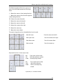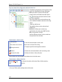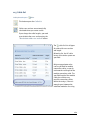
1
PV*SOL
®
Expert:
3D Visualization
Version 6.0
3D-Visualized Coverage, Mounting and Configuration of
Photovoltaic Modules
User Manual
Disclaimer
Great care has been taken in compiling the texts and images. Nevertheless, the possibility
of errors cannot be completely eliminated. The handbook purely provides a product
description and is not to be understood as being of warranted quality under law. The
publisher and authors can accept neither legal responsibility nor any liability for incorrect
information and its consequences. No responsibility is assumed for the information
contained in this handbook.
The software described in this handbook is supplied on the basis of the license agreement
which you accept on installing the program.
No liability claims may be derived from this.
Making copies of the handbook is prohibited.
Copyright und Warenzeichen
PV*SOL® is a registered trademark of Dr. Gerhard Valentin.
Windows Vista®, Windows XP®, and Windows 7® are registered trademarks of Microsoft
Corp. All program names and designations used in this handbook may also be registered
trademarks of their respective manufacturers and may not be used commercially or in any
other way. Errors excepted.
Berlin, 23. January 2013
COPYRIGHT © 1993-2013 Dr. Valentin EnergieSoftware GmbH
Dr. Valentin EnergieSoftware GmbH
Stralauer Platz 34
10243 Berlin
Germany
Valentin Software, Inc.
31915 Rancho California Rd, #200-285
Temecula, CA 92591
USA
Tel.: +49 (0)30 588 439 - 0
Fax: +49 (0)30 588 439 - 11
[email protected]
www.valentin.de
Tel.: +001 951.530.3322
Fax: +001 858.777.5526 fax
[email protected]
http://valentin-software.com/
Management: Dr. Gerhard Valentin
DC Berlin-Charlottenburg, Germany
HRB 84016
1 Introduction
The PV*SOL Expert program from the Berlin-based company Dr. Valentin EnergieSoftware
is the first 3D visualization program for PV systems which provides shading calculations
based on 3D objects for use with the well-known software PV*SOL, a simulation program
for the design and yield calculation of photovoltaic systems. This program enables the
user to realistically illustrate and simulate his PV system.
The PV modules are placed automatically on roofs. With the use of the mouse, objects that
cause shading can be placed and shifted to any position within or outside the PV array.
Chimneys, roof dormers, trees and houses are stored as standard objects in a library.
! In 3D Visualization, it is not possible to calculate more than 2000 modules.
On the basis of the entered objects the program calculates the frequency distribution of
the shading affecting the PV coverage area. This enables a preliminary decision to be
reached regarding the exact roof area to be covered. Through visualization in the 3D mode,
the user is provided with information about the actual track of the shadows over the
course of the day and the year.
The shading calculation produces the time-dependent degree of shading for every module.
In the subsequent simulation in PV*SOL the effects of the shading can be calculated both
per module and per string.
In contrast to previous point-based shading calculations via a horizon line, this new
method produces an area-based calculation via 3D objects. Thus, beside objects on the
horizon outside the PV array, the shading calculation can also take account of objects
within the array as well as the mutual shading among the modules themselves.
This makes the simulated yields produced by PV*SOL much more reliable, particularly for
PV arrays with complicated shading problems.
-> See also: Release Notes: http://www.valentin.de/en/news/product-news
23.Januar 2013
1
2 New features in PV*SOL Expert 6.0
Centering of attic stories and sawtooth roofs
Working with attic stories of buildings and sawtooth roofs as well as walls and chimneys is
now much easier.
If you want to change the width or depth, the side "shift" is automatically centered in order
to maintain a symmetrical form:
Without centering: Unusual roof forms are possible.
With centering: Symmetrical roof forms are simple to display.
Textures
•
Free selection of the textures for all 3D objects, e.g.:
•
o
Buildings
o
Dormers
o
Walls
o
Sawtooth roofs
o
Chimneys
Use of your own, true-to-scale textures makes it
possible to adjust the dimensions of the bricks.
2
New in PVSOL Expert 6.0
Cable plan
Automatic or manual cabling for roof PV systems with a
wide range of functions:
•
Visualization of a cable plan with a range of views and idealized
presentation of module connection cables, string cables and DC trunk
cables as well as bundles, T-plugs, generator terminal boxes, coupling
boxes and cable grommets
•
Automatic cabling by means of the node-string system or the generator
connection box concept (short cable path)
•
Module connection cable for every second module possible
•
Manual drawing of module connection cables
•
Cables can be laid around obstacles
•
Various different cable nodes: bundles, T-plugs, generator connection
boxes, coupling boxes, cable grommets, interceptor nodes
•
Optimization of the cable cross section and calculation of the cable losses
•
Realistic cable list with output of the cable lengths
•
Advanced page setup for printouts in project report
Restrictions:
•
At present no cable plan can be created for mounted systems.
•
At present no cable plan can be created for MPP trackers that extend over several
mounting surfaces.
• Aligning of strings in the module configuration
In the "module configuration" workspace, electric nodes can be fixed to influence the path
of the strings.
3
Manual PV*SOL Expert 6.0
-->
In this example the
length of the string is set to 1.
Other
4
•
Multiple copying of 3D objects and copying of other surfaces of a 3D object
•
Various settings (view options, module spacing, cabling options) are now saved
throughout the entire program, which means that they are preselected the next
time 3D visualization is opened and do not need to be readjusted again each time.
3 Workflow
-> Prerequisites in
PV*SOL Expert:
1. Go to the dialog File > New Project.
2. Select the option
System Planning with 3D Visualization.
3. Confirm with OK.
or open an existing project with 3D visualization.
4. Open the 3D system planning via the menu System > 3D Visualization
3.1 New 3D system
Project Administration >
New 3D system
-> I. Create a new PV system for this project:
1. Go to the menu
Project administration and select the menu item "New 3D
System" . The dialog "New 3D System" opens.
An overview of the project-related data that has already been entered in PV*SOL
will be displayed.
You can now define the settings for a new project:
2. Start by entering a coverable object on which you would like to position your PV
system. Select the roof form that is closest to the building to be simulated.
There are various building forms available, which can be easily scaled, positioned
and oriented later on.
o
o
o
o
Simple Roof Area (rectangular, trapezoidal)
Building (complex) (with pitched roof, tented roof, hipped roof, gabled
roof, mansard roof or high-rise building)
Wall
Open areas.
The selected building form is then shown above, in the drop-down button "PV System
Object with ... ".
4. Clicking the "Start" button. The Terrain view of your new 3D project including the
pre-selected object is displayed.
-> II. Create 3D objects
-> III. System planning
5
3.2 Quick Guide System Planning
-> Plan the system as follows:
Work in the program window from left to right, one working area after the other.
1. Terrain view: Place
buildings and
open areas in the terrain
2. Object view: equip the buildings and open areas with
areas a.s.f.,
3. Give the objects a realistic look by using
4. First
dormers,
restricted
textures.
shading analysis
5. a) Module coverage: Cover the coverable objects with PV modules or module
formations.
or b) Module mounting: Mount modules in rows on the coverable objects.
6. Module wiring: The modules wiring is determined automatically or manually
6
3 System planning
7. Cable plan (optional): Automatic or manual
cable losses
cabling, determines cable list and
Then end the 3D design and import the data to PV*SOL. The actual simulation is run there.
-> Literature:
(1) Leitfaden Photovoltaische Anlagen, chapter 4.7 Verschattung bei aufgeständerten
Solaranlagen; DGS, Deutsche Gesellschaft für Sonnenenergie, DGS Berlin, 2010
7
4 The 3D Visualization Menu
The aim is to determine a configuration of inverters and graphically wire them for a
selection of modules.
The Toolbar, the Project Administration button and the main menu with five different
working areas enable simple navigation and operation of the program.
-> The operating process is divided into working steps:
Terrain View: In the terrain view, you can position and adjust the surrounding objects
which cause shading, such as other buildings, trees and simple objects (walls,
smokestacks, bays).
Object View: Here, the areas of the coverable object are laid out with superstructures,
restricted areas, and other objects causing shadows.
Module Coverage: The system planning starts here with the selection and coverage of the
building surfaces with modules.
Module mounting: mounted systems are planned using the various functions in the
module mounting tab.
Module Configuration: The modules are configured automatically or manually and then
divided into strings.
Cable plan: (optional): automatic or manual cabling, with cable lists and cable losses
Only the symbols for the associated tasks are displayed in every workspace.
Here is the Quick guide.
For a simple introduction to the user interface we recommend our Video tutorials.
8
4.1 Project administration
Directly upon accessing the 3D visualization from
the PV*SOL main menu, you arrive in the main
dialog. Do this by clicking on the project
administration symbol at the top left. A menu is
opened.
-> Please select one of the options on offer for your
next work step:
• In most cases you will start a new project.
You do this by selecting"New 3D System"
. This takes you to the mask New system,
in which you specify the starting
parameters of your 3D system and begin the
3D planning.
•
Save project: Save your previous 3D plans
and results.
•
Import Horizon: You want to import the
horizon from an existing file (see also:
Solar Altitude and Shadows Courses).
•
•
Adopt data: All project data are imported into
PV*SOL. You exit the 3D visualization and
return to the PV*SOL® main menu.
! NOTE: This does not save the data.
Close the window with
.
This
- saves the data.
- imports the data into PV*SOL.
9
4.2 Tool bar
The tool bar is always visible in the 3D visualization.
By clicking on the respective symbol you access the relevant edit dialog or menu.
o
Irradiation generator
In this part of the program you can vary the position of the sun and carry out
animation of sun's course.
o
Object administration
The object administration gives you an overview of all already placed 3D objects in
the form of a check list.
o
Standard view
Click this button to return to the original display (view south, standard
enlargement).
o
Display options
Here you are offered display options, which apply throughout the course of the
program, e.g. show/hide labels, select
texture (grass, sand, stone).
o
Screenshot manager
In this part of the program you can produce and process screen shots for the
project report.
o
Help
You start this online help here.
o
Selection of the coverable object
Here, select the objects or the terrain which can be covered with PV modules.
10
4.3 Solar Altitude and Shadows Courses
Toolbar > Symbol
You can vary the position of the sun and then carry out animations by using the irradiation
generator. The goal here is to visualize in the 3D mode the actual track of the shadows
over the course of the day and the year and thus to investigate what happens on a given
day and time on a particular module that is shaded by a certain object. This is an aid to
decision-making - for example, in determining the extent to which an object causing
shading constitutes an interference. The PV system can be optimized with regard to
shading.
-> Proceed as follows:
1. Access the dialog for the irradiation generator by clicking on the button
toolbar.
in the
2. Two methods of determining the position of the sun are available to you:
Set the direction that the sun is shining either
- directly by specifying the azimuth (0 - 360°) and the elevation angle (0 - 90°) or
- by entering the date and time.
A time of day between sunrise and sunset for every day can be selected.
The time interval for the animation is 10 minutes.
3. Click on the button "Animation" to access the Animation of sun's course.
4. Exit the dialog by using the "Close" button.
11
4.3.1 Animation of Sun's Courses
Toolbar > Symbol
> Animation
With the visualization in the 3D mode you can illustrate the path of the sun and the
shading constellation. The movement of shading over the modules is visible in its
temporal course. You can follow the effects of the shading on the system and delete
modules where necessary.
-> Prerequisites:
1. You have already set the position of the sun in the current project in the dialog
"Solar Altitude" and
2. clicked on the "Animation" button.
3. Arrange the 3D image before the start so that you have an unimpeded view of the
important areas of your 3D project.
-> Proceed as follows:
1. First specify the starting date (e.g. 01.01.) and the closing date (e.g. 31.12.) of the
animation.
The dates must be in a sensible order and may not cross over each other. This
produces the number of days over which the animation should take place.
2. Specify whether an animation should be repeated at the end by checking the
option "Continuous Loop".
3. Adjust the speed of the animation via a slide control.
The time interval for the animation is 10 minutes.
13
Manual PV*SOL Expert 6.0
4. Start the actual animation by clicking on the "Start" button.
As a result the shading caused by the object is animated.
During the animation the date and time of the animation are shown under "Current
Date:" and "True Solar Time:".
5. The button subsequently changes to "Stop". Another click stops the animation.
14
4.4 Object administration
Symbol
Object Administration in the Toolbar
Object administration gives you an overview of the 3D objects already set in the project
and shows these grouped into certain categories. Using this dialog means you will not
have to search very long to find objects you have already set up; this dialog can also be
used if you wish to obtain an overview of the progress of your project.
The 3D objects are arranged here exactly as in a typical directory tree structure.
You can work through to the desired object by clicking on the appropriate elements.
Clicking on one of the objects in the object administration directs the 3D camera to this 3D
object, so that you can edit it.
Right-clicking on the object opens the associated
context menu ("Copy", "Remove", "Add to manual
configuration" , etc.) appropriate to this object's type.
Use the buttons in the left upper corner to expand
and collaps
all directories, respectively.
15
4.5 Standard View and View Options
4.5.1 Standard view
If you wish to return to a defined starting state in the 3D world, then select the menu item
"Standard View"
in the toolbar by clicking on the symbol.
The camera will then return you to the standard position and orientation. The camera
position depends on the currently selected view.
If you are in "Roof Coverage", for example, this procedure will then return you to a
standard view of the roof, while a view from the south is the standard setting in the terrain
view.
4.5.2 Display options
Use the small black arrow to the right of the toolbar icon "Tool"
down menu with the following menu items:
to open the pull-
Show Restricted Areas
Show Coordinate Grid
Show Text
Select Texture (grass, stone, sand, earth)
There are four different texture sets:
Grass:
Stone:
Sand:
Earth:
Textures are saved with the project.
New projects and open areas use the selected texture.
16
4.6 Screenshot manager
In the screenshot manager, you can create, assign to categories, and manage screenshots
of current views for presentation in the project report or for archiving purposes.
A screenshot with the entire 3D display area from the 3D visualization is created. The
mouse pointer and display elements that are part of the 3D scene are not taken into
account here. The view that was visible before the dialog was opened and the shot was
taken is reproduced in the photo.
-> Proceed as follows:
1. In the toolbar
.
click on the camera button
The screenshot manager will be displayed.
2. Select a project report category by clicking the corresponding tab:
•
Shade environment
•
Module coverage
•
Module configuration
•
Shade frequency distribution
The photo can also be assigned to a category later on (see below).
3. Click the "Shutter Release" button to take a photo of the view currently displayed
behind the dialog. The screenshot is saved as a bitmap image in this category, and
is displayed as a minimized image.
17
Manual PV*SOL Expert 6.0
4. Right click the photo. A context menu is displayed, which offers the following
editing options:
•
Allocate category: Moves the screenshot to another category. Another
context menu will be displayed here which contains the three other
categories (see above).
•
Add image text: This text to be used as screenshot caption in the project
report.
•
Remove: Deletes the selected screenshot.
•
Remove all: Deletes all screenshots.
5. If you left click with the mouse on an image element in the selection, the program
view as visible in the screenshot will be restored. This means you are able to
update the screenshot if necessary.
6. To save your screenshots, click the “Save All” button. The screenshots in all
categories are saved in a folder of your choice.
The screenshots in the screenshot manager are saved with the project and can
thus be further edited after the project has been loaded again.
You can use these screenshots in the detailed project report after closing the 3D
visualization.
18
5 Program operation
In general there are several editing methods:
•
Double click on an object
•
Right click on an object to open the context menu
•
Click on the button in the side menu (where available)
You can find details at:
•
Coverable Objects
•
Mouse operation and keyboard shortcuts
•
Position and orientation of objects
•
Drag and drop
•
Copy row of modules/module array
•
Integration and separation
•
Multiple selection
•
Enter distances
•
Colors for frequency distribution
•
Status bar
•
Tutorials and Webinars
For a simple introduction to the user interface we recommend our video tutorials and
webinars.
19
5.1 Coverable Objects
Terrain View
Coverable objects can be covered with PV modules and shading objects.
Add
When you are in terrain view, the context menu can be opened by right-clicking the object.
Then select "Add to coverable objects".
The following objects
can be added to the
coverable objects.
•
Open area
•
Building
•
Bay
•
Wall
•
Dormer
•
saw tooth
roof
•
Projecting
roof
Activate
By means of the Activate context menu, switch to object view, where you can insert further
details into the object positioned in the terrain view.
If you want to make a coverable object into a non-coverable object, switch to terrain view
and then select "Remove from coverable objects" in the context menu (right click).
Remove
If you want to make a coverable object into a non-coverable object, switch to terrain view,
open the context menu by right-clicking, and then select "Remove from Coverable
Objects".
Alternate
You can alternate between the coverable objects via the menu on the right-hand side of
the toolbar.
20
Coverable Objects
Edit
The edit dialog is opened by double-clicking on the object.
Alternatively, you can right-click on the object and select "Edit" in the context menu.
For open areas, buildings, bays and walls, FIRST switch to the Terrain view workspace:
Set point of origin
If you right-click on a coverable object and select the "Set point of origin here" option, the
coverable object is set to the point of origin. This simplifies the positioning of surrounding
objects.
-> See also:
Position and Orientation of Objects
Drag and Drop
Multiple selection
21
5.2 Create 3D objects
The complete operation process is consistently divided into working steps which makes
the work considerably easier.
All 3D objects which cause shading, such as buildings, trees, inactive windows and barred
areas, are dragged onto the working surface with the mouse. The working surface displays
a circular section of the hemisphere measuring 300 x 300 m. A scale grid (freely
adjustable), which is marked on the terrain and the hemisphere, is used for orientation
during placement of the 3D objects. The position of the 3D objects is specified relative to
the point of origin. Roof objects are adjusted in relation the their reference area.
It is possible to rework every already positioned 3D object with a simple mouse click.
The coverable object
The 3D visualization begins with the setting of a coverable object. For example, a roof form
can be selected from a collection of common building types. The building positioned in the
3D scene can then be scaled on the basis of the dimensions of the original. It is possible to
depict the individual areas of the roof with millimeter precision by entering roof
projections and barred areas.
Direct barred and shading objects on the coverable object
After the dimensioning work on the building has been completed, in the next work step the
barred objects such as windows and scalable barred areas can be installed on the
coverable object, as well as objects which cause shading such as chimneys and dormers.
A pan shot enables the angle of vision in the 3D scene to be constantly focused on the
desired part of the roof. This enables passive and active 3D elements to be interactively
placed and adjusted on all the surfaces marked as PV areas. As an operating aid,
automatic labelling and dimensioning are available to the user in the PV covering mode.
Barring frames can also be defined in the base area of every
object.
Shading surrounding area
With the help of the program, the user can at any time position and adjust the surrounding
objects which cause shading such as other buildings, trees and simple objects (walls,
masts, etc.).
In the case of the trees, differentiation is made between constant transparent (conifers)
and seasonally variable (deciduous) trees, whilst other objects are graded as opaque.
22
2 The creation of 3D objects
Animation of sun and shadow
Depict virtual positions of the sun through azimuth and elevation angles or by means of
time specification and follow the path of the sun in a freely selectable time span. Besides
the visual presentation, this also serves the decision-making, e.g. how far an object
causing shading constitutes an interference.
The horizon
The program allows the setting of a horizon. The user defines mountain ranges and other
features on the distant horizon. Import previously saved files of obstruction elevations created
with a Solmetric Suneye or horizon lines created by horizON software.
When importing files, take care to first remove any spurious objects in the sky as otherwise there
will be unwanted tall objects created on the far horizon. It is, however, not recommended to integrate nearby shading objects into the horizon as this will
not benefit from the 3D function. Any near shading objects already captured in the horizon sketch
will need to be removed from any far horizon sketches or imported horizon files. This is to avoid
duplication of the same object when nearby object are created in PV*SOL Expert.
23
5.3 Change textures
Terrain view / Object view >
Change textures context menu
It is now possible to exchange the textures of various different active 3D objects, e.g.
buildings, dormers, chimneys etc. and save them in the project in the 3D visualization of
PV*SOL Expert 6.0 .
-> Requirement:
The object is active, i.e. you are in the terrain view or object view.
-> To select a different texture:
1. Select any 3D object in the 3D visualization.
2. Select
the menu point Change texture in the context menu
(right click).
The "Change texture" dialog box opens.
- The selected object will be renamed.
- For several objects, such as buildings or dormers for instance,
the selected floor or the story will be displayed,
e.g.: "Marked is: attic story1 from buildings 02".
You can swap over the textures for the sub-object independently
of the buildings for these objects.
- The currently used textures of the 3D objects are listed at the left.
Every object can possess several textures.
3. Click on the texture to select a different texture.
The surfaces are listed in the middle and the textures that have
been applied to them are listed on the left.
- As long as the option "List textures individually" is not set, the surfaces
will be collectively listed together with the same texture.
- If the option "List textures individually" is set, the textures for every
outer surface of the 3D object will be individually listed.
- If you set this option and then remove it, the program will collect the same
textures.
Note: the textures are always immediately replaced.
4. The Standard values button resets all changed textures back to their
default values.
24
Manual PV*SOL Expert 6.0
-> To edit textures:
1. Change the texture of a surface with the
button.
The dialog box "Edit textures" opens.
The active textures can be edited here or a new texture can be created and
assigned.
2. Change the texture with the help of the drop-down button , which displays the
texture.
The description is automatically adjusted. Every system texture has a definite
description.
3. Select an option for Tiling
25
the texture:
Option
Tiling
Extension
horizontal
/ vertical
horizontal
/ vertical
-
horizontal
horizontal
vertical
vertical
vertical
horizontal
Example
Change textures
no tiling
-
horizontal
/ vertical
4. Enter the measurements for the tiles. Example: widths of 0.5 m mean that a tile of
this texture covers a 3D object with a width of 0.5 m. With this option also, e.g. an
actually rectangular texture can be created etc.
Note: If you enter here the actual dimensions of a roof tile, you can count the tiled
tiles on the roof to determine the distance of the roof object to the edge of the
roof.
-> To add new textures:
1. Click on the "New" button to load an image file.
The file will automatically be added to the program-internal collection of textures.
Note: Own textures are only saved with this project! Create a collection of textures
for your projects in any directory.
2. The following formats are supported:
.jpg, .jpeg, .bmp, .png
3. The files may not be larger than 1024x1024 pixels. It is recommended that 512x512
pixels are not exceeded.
4. The image will be displayed in the same way as a system texture. The description is
automatically taken from the file name.
Select an option for the tiling.
Enter the actual dimensions of the object depicted on the image. This cannot be
automatically determined by the program. The values displayed by the system are
estimates in this case.
-> To delete textures:
1. Click on the
yourself.
button to remove from the project again textures you have added
2. Textures used in the project and system textures cannot be deleted.
Objects whose texture cannot be changed:
Excluded here are open areas and inclined open areas, as these continue to be selected
over the menu Options > Texture and are set together with the terrain and the background.
Also the restricted areas are initially excluded, as they occupy a special role in the
program. The modules and direction arrows are also excluded
26
5.4 Mouse operation and keyboard shortcuts
Program operation in 3D planning is based on modern navigation using the mouse and
keyboard. All 3D objects can be dragged onto the working surface with the mouse. The
working surface displays a circular section of the hemisphere measuring 300 x 300 m,
where one can move by means of a pan camera shot in order to obtain various perspective
views of the 3D scene.
The following overviews explain the mouse and keyboard functions for camera movements
in the object view and in module coverage.
Mouse functions
Left mouse key
Selecting individual modules (only
Module coverage)
Left mouse key,
double click
Editing the currently marked 3D
object (Terrain view / Object view /
Module coverage)
Left mouse key
pressed +
moving the
mouse
Moving 3D objects (Terrain view /
Object view / Module coverage)
Expanding module formations
(Module coverage)
Selecting modules (Module
coverage / Module configuration)
Rolling the
scroll wheel on
the mouse
Zooming (camera is moved in or
out)
Scroll wheel
pressed +
moving the
mouse
Camera moves about the vertical
and horizontal axis
Right mouse
key
Action key; various pop-up menus
are displayed; objects can be
edited
Keyboard functions for camera movements
28
Mouse operation and keyboard shortcuts
The following keyboard functions apply to all
views, but are limited somewhat in the object
views.
'+' - Moves the camera in the viewing direction
'-' - Moves the camera in the direction opposite
to the viewing direction
'W' - Moves the camera forwards
'S' - Moves the camera backwards
'A' - Moves the camera to the left
'D' - Moves the camera to the right
'R' - Moves the camera up
'F' - Moves the camera down
The numeric keypad must be activated before it can be used.
Num left arrow
Pans the camera to the left
Num right arrow
Pans the camera to the right
Num down arrow
Pans the camera down
Num up arrow
Pans the camera up
Keyboard functions in the object view:
Alt +
left
arrow
Pans to the surface to the
left of the reference surface
currently being viewed
Alt +
right
arrow
Pans to the surface to the
right of the reference
surface currently being
viewed
If possible, i.e. if there are other
29
Manual PV*SOL Expert 6.0
floors present:
Alt +
arrow
down
Pans to the surface
underneath the reference
surface currently being
viewed
Alt +
arrow
up
Pans to the surface above
the reference surface
currently being viewed
Keyboard functions in module coverage:
Ctrl
+A
30
Marks all modules
on the current
coverage surface
5.5 Position and Orientation of Objects
When editing objects, you are always offered the functions for positioning and orientation
of the 3D object in the respective edit dialog in the separate lower part of the mask.
As a result the 3D objects are reassembled and rotated in the 3D scene on the basis of the
input data. The compass shows the direction which the front of the 3D object is currently
facing.
This dialog section is originally the same for all freely adjustable objects. It always works
the same way. Parts are only hidden, such as the orientation, if a 3D object cannot carry
out a particular operation.
+
-> Proceed as follows:
1. Enter the position via two input fields as the distance in metres from the origin in
both the x-direction and the y-direction.
The reference point for the position data is the lower left corner on the roof, and
the zero point / point of origin in the terrain.
2. Enter the orientation using the 360° format.
Compass Point
Orientation
North
0/360°
East
90°
South
180°
West
270°
3. The current direction is shown by the points of the compass.
4. Close the dialog. The 3D object is accordingly rebuilt and rotated in the terrain
view.
31
5.6 Drag and drop
The so-called "drag and drop" method is used for positioning objects throughout the
program, meaning, you can drag all movable objects to any possible position and drop it
there.
Click on the required object and drag the mouse with pressed left key over the selected
button until the drag symbol appears at the end of the cursor arrow. At the moment you
leave the button, the menu is closed and the selected 3D object appears on the cursor. It
now moves with the cursor until you release the pressed mouse key at the desired position
(drop).
Collision Test
The 3D object is colored red as long as it is moved over a prohibited area. This often occurs
with roof objects, because they may only be placed in a free PV area. As soon as it is
situated in a permitted area the object is displayed in green.
As soon as the roof edge or another object bars the placement area, this is detected by a
collision test and the placement of the object is denied. If an object is placed by dropping
anyway, it will be deleted without notification.
Deactivate Collision
32
5.7 Copy row of modules/module array
-> How to copy a row of modules or a module array:
1. Go to "module mounting"
2. Go to the "copy" context menu. The dialog "Clipboard" is opened.
3. Any objects which can be copied (rows of modules or module row arrays) are listed.
4. Select the desired object or
5. close the dialog.
33
5.8 Module Integration and Separation
The integration and separation procedure is used for module formations.
A module formation describes a group of modules of the same type, which may only be
arranged in the existing grid. The grid can be specified individually for every module
formation and consists of a combination of the module dimensions and internal distances
between the modules (the latter can be changed by the user at any time). According to this
principle, single modules or complete module formations can only be integrated into an
existing formation if they are of the same module type and are on the same area. They can
be deleted at any time, but not dragged off the grid. If the user wishes to do this anyway,
he must separate a highlighted group of modules from the highlighted module formation.
The newly created module formation can then be freely processed and placed. At the same
time a collision check is run internally, according to which the 3D objects may only move in
the zones of a PV area which are still uncovered! Thus the scaling is always restricted to
dimensions that cannot lead to a collision with other 3D objects!
Module formations can be compiled according to three different procedure models:
1. by assembling single modules to create formations,
2. by expanding formations with the mouse or
3. with the method of automatic module distribution, which uses all of the free PV
coverage area.
Integration
If you want to integrate an individual module (a formation with only one module) or an
entire formation into another formation, drag the formation to be integrated close to the
target formation. An internal mechanism automatically detects that it is in the sphere of
influence of the target formation and shows the formation grid. You then drop the
formation, and the modules it contains are transferred to the target formation according to
the given grid. The original formation is deleted during this process.
34
Module Integration and Separation
Separation
In the reverse procedure, the user wishes to separate modules from a formation, e.g. in
order to move them independently. Here a group of modules of the original formation is
selected with the mouse followed by a right mouse click. A context menu appears. Here
the menu item "Selection" is activated. Click on "Remove" in the submenu and the
selected modules are converted into an independent formation.
-> see also:
Drag and Drop
35
5.9 Select an object
Click on an object. It is shown in blue.
5.9.1 Select several objects simultaneously
Using the multiple selection, you can conveniently select certain module rows, for example
to then configure them together.
Which objects may be selected is dependent on the chosen edit mode.
•
Terrain view: all objects which can be placed on the terrain can be selected
simultaneously here. Trees, walls, chimneys, buildings etc.
•
Object View: all objects which can be placed on a reference object can be selected
simultaneously here. Dormers, chimneys, windows, restricted area etc., but no
module arrays or row arrays!
•
Module coverage: module arrays, but not row arrays, can be selected here
•
Module mounting: row arrays, but not module arrays, can be selected here
•
Configuration: module arrays or row arrays can be selected here for configuration.
-> How to select several objects simultaneously:
Either click on an object with the left mouse button while holding
down the ctrl key and then click on the next object.
Both are then highlighted in blue.
Or hold the left mouse button down while moving the mouse over the desired objects. A
rectangle is drawn and the selected objects are highlighted in blue.
Objects selected together can be deleted together.
36
5.10 Enter distances
Terrain view or Object View or Module coverage > (any object) > Enter distances
You can enter distances between objects instead of
absolute positions.
-> How to proceed:
1. Select the desired object.
2. In the context menu (right click), select "Enter distances".
The adjacent 3D objects are automatically calculated. This also includes the PV
area itself, as you can enter the distance to the edge.
• The "Enter distances" dialog opens.
• Current object: The current object is shown in a transparent shade of blue.
3. PV system object: further objects are available for selection as PV system objects
in the associated drop-down list.
The PV system object is shown in bordeaux red.
37
Manual PV*SOL Expert 6.0
4. Distance in x-direction, distance in y-direction:
• Select the direction in which the distance is to be entered.
• You can select left and right for the horizontal distance and front and back for the
vertical distance.
• If you change the direction, the program assumes that you want to reposition the
object. As a precaution, you will be asked to confirm this.
If you click OK, the object is moved into the desired direction.
If you click Cancel, the existing distance, measured in the new but incorrect
direction and therefore as a negative value, is shown.
5. Select the Corner, from which the distance is to be entered.
• Every time the direction is changed, a plausible corner is automatically
determined. If you would like to choose a different corner, use the Corner dropdown menu.
• The drop-down button is marked with a red strip. This indicates that the selected
corner is currently also visualized in the 3D editor.
• Every time the direction or the corner is changed, the distance shown is updated.
In this way, you can measure fixed distances.
6. Enter the desired distance in the editing field. The distance is updated and
visualized.
Minimum and maximum values are determined by the space currently available
before a collision with uninvolved objects and the edge of the PV area occurs.
7. Save your entries by clicking OK.
! If it is not possible to find an ideal corner, e.g. because both objects are at almost
the same height, an atypical corner is then selected (see Align 3D objects).
! Notes:
38
•
If the PV system object is not at the same height, the distances to the guideline are
shown or entered at the bounding box of the PV system object.
•
If the PV area is trapezoidal or triangular, different distances to the edge are shown
for all corners.
•
If the object to be positioned is round, then points, not corners, are shown.
•
Restricted border areas and edge distances are only of significance for the module
coverage and not taken into account when entering distances.
•
The appearance of the sizing arrows is always only shown for one direction and
changes if you click on drop-down menus or editing fields in the other direction.
5.11 Shading frequency distribution
A shading analysis shows the annual direct irradiation reduction on the basis of the
seasonal frequency distribution of shading on the areas of the coverable object.
For every grid point on the current PV area, the irradiation reduction is calculated as an
annual average and can then be graphically evaluated by the user.
-> Prerequisites:
All the objects that cause shading have been positioned and subsequently scaled.
-> Proceed as follows:
1. Go to the menu "Shade Frequency Distribution", in either the workspace Module
Coverage, Module Mounting or Module Configuration.
Only the "Calculate" button is activated.
2. Set, where the shade frequency distribution shall be calculated:
In the Module Coverage editing mode, this button is always disabled
o
(grey).
39
Manual PV*SOL Expert 6.0
o
In the Module Mounting editing mode, shade frequency is calculated for:
the level of the active solar surface, LED is not lit
on the module rows, LED is lit
3. Please click on the "Calculate" button. The calculation may take some seconds.
Then the direct irradiation reduction is displayed both in figures and colors for
each point on the grid of the current PV area.
After the calculation of the shading frequency distribution colored fields are shown
on the PV area. Every color symbolizes a particular annual irradiation reduction. If a
formation is adjusted, the display of the annual irradiation reduction on the
modules changes.
Click on the
symbol to set the color values. The
following shading analysis.
symbol only becomes active
4. Once the results of the frequency distribution are available, they can be shown or
hidden by the user at any time.
5. Place the modules and arrange them in formations on the basis of the frequency
distribution. Single modules affected by the shading too much, can also be
deleted.
Note:
As soon as a shading-relevant object is newly positioned or its dimensions are
changed, rotated or adjusted, the user is automatically prompted to remove
the current frequency distribution, because from this moment on it is no longer
applicable.
At present, the shading frequency distribution must be recalculated every time a
project is loaded!
At the moment, a frequency distribution can only be simultaneously calculated for
one PV area!
5.11.1 Adapt string course to shading
The display of the shading frequency is also useful with regard to the module wiring. It
enables the optimal string wiring to be determined step by step.
Exchange modules within the individual strings without adding new modules or removing
existing ones.
40
Shading frequency distribution
Goal: You can - depending on the layout - exchange individual modules until all similarly
shaded modules are contained within one string each.
Several display levels have therefore been introduced to enable the practical combined
display of frequency distribution and module configuration.
Display only irradiation
reduction and color
distribution. For this, activate
the button-->
Display only color
distribution. For this,
deactivate the button -->
Combined display of
irradiation reduction and
color framing values from
configuration. For this,
activate the button--> in the
"Module Configuration”
area.
41
Manual PV*SOL Expert 6.0
42
5.11.2 Colors for frequency distribution
Different settings, such as the color scale, can be realized and edited for the frequency
distribution.
You access this dialog by clicking the symbol in the work step Shading frequency
distribution of the two working areas Module coverage and Module configuration
The symbol only becomes active after an initial shading analysis has been made on the
basis of the seasonal frequency distribution of shading. This initial shading analysis
serves solely for orientation.
43
5.12 Status bar
The status of the currently marked 3D object is displayed for your information at the
bottom edge of the screen. The structure of the status bar depends on the currently active
view and whether one or several objects have been selected.
Terrain view
The following information is listed, from left to right:
•
Object type
•
x coordinate from point of origin in metres
•
y coordinate from point of origin in metres
•
Distance 1 in metres
•
Distance 2 in metres
•
Distance 3 in metres
•
Distance 4 in metres
The distance of the object from the corners of the coverable object is displayed. The
corners are identified after orientation has been defined.
Object View
The following information is listed, from left to right:
•
Object type
•
x coordinate from point of origin in metres
•
y coordinate from point of origin in metres
•
Distance 1 in metres
•
Distance 2 in metres
•
Distance 3 in metres
•
Distance 4 in metres
The distance to the edges of the PV area is displayed.
44
5.13 Video tutorials
On our web site http://www.valentin.de/sales-service/produktschulungen/tutorials you
find provided our German video tutorials:
•
Operation of 3D visualization in PV*SOL® Expert: "Bedienung der 3DVisualisierung in PV*SOL® Expert"
•
Detailed introduction to system planning with 3D visualization in PV*SOL® Expert:
"Detaillierte Einführung in die Anlagenplanung mit der 3D-Visualisierung in
PV*SOL® Expert"
On our web site http://www.valentin.de/sites/default/files/tutorials/pvsol-expert.swf you
find provided:
•
Introductory video for PV*SOL® Expert: http://www.valentin.de/en/salesservice/product-training/tutorials
On our web site http://www.valentin.de/en/sales-service/product-training/webinars you
find provided contents and appointed dates of our interactive, online webinars and you
can register for them.
45
6 Introduction to the terrain view
In terrain view, you can look around freely by panning (middle mouse button).
You can select, arrange and scale the appropriate objects under the menu items "Trees",
"Buildings" and "Other".
Double-clicking or right-clicking --> Edit on an object opens it's edit menu.
By means of the Activate context menu, switch to object view, where you can insert further
details into the object positioned in the terrain view.
Horizon
You edit the horizon here. The dialog for delineating a horizon line is accessed via the
"Horizon" button.
Define mountain ranges and other features on the distant horizon only to represent the
behavior of the sun at sunrise and sunset.
It is, however, not possible to integrate shading objects into the horizon. This has
eliminated an important source of error in terms of perspective.
The horizon interfaces to "Horizon".
Views
You can set various angles of vision for the 3D object or the terrain
via the drop-down button "Views".
The selected view is then shown in the drop-down button "Views".
The standard view in the main window is changed accordingly. Now
you can view your 3D scene from the set perspective.
By clicking on the symbol Standard view in the Toolbar you can
revert to the original preset south-facing view at any time.
46
6.1 Open Areas
Terrain view >
Open Areas
Using the "Open Area " object, open-space systems with and without gradients can be
depicted. The open area without gradient can be used to align several objects together.
-> How to proceed:
1. Go to the Terrain view >
2. Select either a flat
terrain.
Open Area dialog.
Open Area or a
Tilted Open Area and drag it onto the
3. Add the open area to the Coverable objects.
Rule: the open area may not be placed over other 3D objects.
Note: To better manage open areas, the collision test has been expanded to cover all
3D objects placed on the terrain.
Two objects can now only be pushed into one another once collision is switched
off (context menu "Deactivate collision").
4. Open the edit dialog (double-click or context menu Edit (right click)).
w ... Width
d ... Distance
β ... Tilt angle
(h ... Height)
5. Scale the open area:
width and length must each be between 5 and 300 m. The inclination can be set to
between 0 and 90°.
47
Manual PV*SOL Expert 6.0
6. Position the open area:
the open area can be freely moved within the limits of the terrain. Collision can be
switched off. The diameter of the terrain is 800 m.
7. Orient the open area:
the open area can be oriented in angles from 0 to 360°.
8. Close the edit dialog.
9. Add the open area to the coverable objects (context menu, right click).
10. Activate the open area (context menu, right click) to switch to the Object view
workspace and cover it there.
See also: Open Area in object view
Rule: Two open areas may not be stacked on top of each other.
Rule: Several open areas may be defined.
Building on the slope
To ensure the building does not float in the air, a
compensatory storey has been introduced.
This storey automatically adjusts to the
dimensions of the building.
At the start, the building is automatically aligned
exactly like the slope and the compensatory
storey does not appear.
It is first shown when the building is oriented
relative to the slope and the slope has an
inclination greater than 0°.
You can work without the compensatory storey by only rotating the building up to 90°
counter-clockwise relative to the slope. As a result, the first floor extends into the slope.
You must, however, modify this manually when entering the height of the building!
If the orientation of the slope is 180° south, the compensatory storey appears in the angle
range from 180° to 360° and from 0° to 90°.
Like all other rotatable objects, buildings collide with other 3D objects in their way when
rotating.
48
6.2 Simple Roof Area
The dialog is available for simple building forms, with which you can scale, position and
orientate a roof surface or other PV areas in the simplest way. The user can add and
remove floors and attic floors to the building.
The function is intended for the user who only wishes to make a module coverage and
shading calculation for a single roof area. Here, less emphasis is placed on graphic
attention to detail. The building around the roof area serves only for spatial accentuation
of the area! Only the scalable roof area is relevant!
The roof area is described by the length and height of the eaves, their distance to the
ridge, the length of the ridge, the pitch of the roof and the orientation.
-> Conditions for the simple building edit mode are:
• The building has been created as a "Simple Roof Area" type (see New 3D
system).
•
only one ground floor exists,
•
only one attic floor exists,
•
no roof overhangs are defined.
! If you have made advanced settings in the dialog for complex buildings, you
cannot return to the simple dialog until these settings have been withdrawn.
w1 ... Lengt,
Eaves
d ... Distance EavesRidge
β ... Roof Pitch
h ... Height Eaves
h ... Height
Eaves
Refine Form:
w2 ... Length
Ridge
m ... Shift of
Ridge
-> Define your building as follows:
1. To edit a building, switch to terrain view and double-click on the building. You
access this dialog with a double click on your building.
2. The entries are made via several input fields and controls in the following dialog.
Please take the assignment of the individual input parameters for the building
from the two schematic diagrams above.
49
Manual PV*SOL Expert 6.0
•
•
To the left of the mask are the elements required to edit simple basic forms of
roof areas (rectangular, square).
To the right, after clicking the parameter Refine Form, additional scaling
options can be implemented (trapezoid, parallelogram, triangle, etc.).
New in 6.0: If the option Centered is set, the shift is automatically
adjusted to retain a symmetrical form.
3. One can change to an extended dialog via the "Mode" menu item, in which it is
possible to define an entire building (see Building (complex) ).
4. As a result of the settings the roof surface expands or contracts in its dimensions,
shifts in space, rotates in space or changes its pitch.
-> See also:
Building (complex)
Drag and Drop: Collision
Position and orientation of objects
Building on the slope
50
6.3 Building (complex)
System > 3D visualization > Terrain view > double click object
To edit a building, switch to Terrain view and double-click on the building or select "Edit"
in the context menu (right click on building).
You can realize complex building forms by scaling, positioning and orientating an entire
building to an individual design.
The user can add and remove floors and attic floors to the building.
Warning: Please note that roof overhangs must be added to the dimensions of the top
floor.
Storeys
Attic Storeys
Storeys can be modified
independently of the storey
below.
The floor area of an
attic storey always
adapts to the storey
or attic storey
located below it.
Width
Width of
storey
Width
Width of
ceiling area
of attic
storey
Height
Height of
storey
Height
Height of
attic storey
Depth
Depth of
storey
Depth
Depth of
ceiling area
of attic
storey
-
If you want to
change the
width or
depth, the
side shift is
automatically
centered in
order to
maintain a
symmetrical
Centered
-
51
Manual PV*SOL Expert 6.0
form:
Symmetrical
roof forms
are simple to
display.
not centered
-
-
Shift, width
Shift of
Shift,
entire story
width
(not for ground in width
floor)
Shift, depth
Shift of
Shift,
entire story
depth
(not for ground in depth
floor)
"Adapt All to Floor Plan" adapts
all storeys (not attic storeys) to
the width and depth of the
ground floor.
Unusual roof
forms are
possible.
Shift of
ceiling area
of attic
storey in
width
Shift of
ceiling area
of attic
storey in
depth
Definition of Roof
Overhangs
Please also refer to the schematic diagrams (see below) for the assignment of the
individual input parameters.
Generally, the floor and roof levels can be accessed via the tabulators "Storey" and "Roof".
When accessed, the dialog changes to the correct page and adjusts its parameters to the
floor that is currently marked. You can change to the other floors via the ComboBox at the
top left.
The "Insert" button is used to create a new floor of the previous type. Conversely, the
"Remove" button is used to remove the current floor.
Note: The ground floor and the top floor cannot be removed! A building always
consists of at least a ground floor and a top floor (if necessary this has a height
of 0).
You can return to the simple dialog via the "Mode" menu item, if:
•
52
only one ground floor exists,
Building (complex)
•
only one attic floor exists, and
•
no roof overhangs are defined.
If you have made advanced settings in the dialog for complex buildings, you cannot return
to the simple dialog until these settings have been withdrawn.
m ... Shift, Depth
d2 ... Depth, roof (here 0)
h2 ... Height, roof
o ... Overhang, eaves
t ... ... Thickness, roof
h1 ... Height, storey
d1 ... Depth, storey
m ... Shift, Width (here 0)
w2 ... Width
o1 ... Overhang, left
o2 ... Overhang, right
w1 ... width, storey
-> See also:
Building (simple)
Position and orientation of objects
Buildings on a slope
Roof overhang
53
6.4 Roof overhang
Terrain View > Buiilding (complex) > Edit > Attic Storeys > Roof Overhang
Warning: Please note that roof overhangs must be added to the dimensions of the top
floor.
For example, the shading of facade modules is often caused by the building's own roof
overhang.
-> Proceed as follows:
1. Go to the Terrain view > Building (complex) dialog.
2. Add the building to the coverable objects, if this has not already been done.
3. Open the edit dialog (right click) and go to Attic Storeys.
4. As required, select an attic storey.
5. Click the Roof overhang button in the Options area.
6. Define roof overhangs left and right from the gable as well as over the front of the
storey below.
The overhangs can be entered separately for all four possible roof areas of a roof
level or together for opposite roof areas.
The tabulator symbolizes the individual roof areas of a top floor. The labelling of
these areas is adapted to the direction they are facing.
54
Roof overhang
With a click on the tabulator, the angle of vision pans so that the active roof areas
are shown in the 3D scene. With the setting of the overhangs, the roof area
expands or contracts in its dimensions. The total dimensions of the roof area
determined from the changes to the roof overhang are immediately displayed in
the 3D scene.
55
6.5 Tree
An object of the type "Tree" is only required in the project if there is a need to analyse
shading by a tree.
You can select different types of trees and arrange and scale them in the terrain via the
menu item "Trees" in the working area "Terrain View". Differentiation is made between
constant transparent (conifers) and seasonally variable (deciduous) trees. The tree objects
can be moved freely within the 3D scene.
Special requirements apply for the implementation of trees. The seasonally variable
degree of transmittance of the tree tops, caused by continuous leaf growth and
defoliation, should be taken into account in the shading calculation. But, above all, the
silhouette of the tree top of the 3D object should match the real example as closely as
possible.
With a double click on the tree object one accesses the editing dialog with which these
requirements can be implemented. The dialog also opens with a right mouse click and
selection of "Edit" from the pop-up menu.
The dimensions of the tree top and the trunk can be varied independently of each other. By
changing the focal point a wide variety of tree tops can be depicted.
Please take the assignment of the individual input parameters from the schematic
diagram.
56
Tree
d2 ... Diameter, Crown
h1 ... Height, Crown
hG ... Height, Centre of
Gravity
h ... Height, Tree
d1 ... Diameter, Trunk
Changes to the focal point are made on the basis of a scale from 0 to 1 related to the
height of the tree tops. In geometric terms, this moves the sphere, which is the basis of
the geometric body of the tree top, up or down. The tree top is repositioned in space.
Note: Because a tree object is symmetrical, it cannot be oriented.
The "Transmittance Degrees" button leads to a further dialog, in which one can enter any
overall degree of transmittance through the foliage of the tree top for every month.
-> See also:
Position and orientation of objects
57
6.5.1 Trees - degree of transmittance
Terrain View > Trees > Edit > Degree of Transmittance
Here, you can display the seasonally varying transmittances (degrees of permeability)
through the tree crown in the results of the shading analyses.
-> Proceed as follows:
1. Go to the Terrain view > Trees > Edit > Degrees of transmittance dialog. The
designation of the active tree object always appears in the header of the dialog.
2. Enter a degree of transmittance in percent (0 - 100 %) for every month of the year.
These values are saved for every tree in the project.
3. Close the dialog with OK.
The different transmittance degrees are taken into account in the shading frequency
distribution and the simulation.
Note: The different degrees of foliation are not presented graphically in the 3D
scene.
-> See also:
Position and orientation of objects
Tree dialog.
58
6.6 Wall
Terrain View > Others > Wall > Edit
Object View > (open area active) > Wall > Edit
Here, you can generate simple 3D objects which cause shading, e.g. a wall or a mast and
both lay them out and scale them freely on the terrain or an open area.
The simple wall is rotatable on the ground (= in terrain view) but not on an open area (= in
object view).
The simple wall is pushed into the open area when increasing the width or length.
This type of object is always valued as opaque (impervious to light).
-> Proceed as follows:
1. Go to the working area "Terrain View", menu item "Other". Open the editing dialog
by double-clicking the wall.
Please take the assignment of the individual input parameters from the two
schematic diagrams:
m ... Shift, Depth
d2 ... Depth, Covering Area
h ... Height
d1 ... Depth, Ground Area
m ... Shift, Width
w2 ... Width, Covering Area
h ... Height
w1 ... Width, Ground Area
2. You define a simple, uniformly right-angled (orthogonal) 3D object such as a cube
or cuboid under Ground area.
3. Check the
Refine form box, to display more complex 3D objects.
59
Manual PV*SOL Expert 6.0
4. The dimensions of the base and covering area can be independently varied.
In this way, the pitch of the 4 lateral surfaces of the body can be adjusted. This
enables objects such as pyramid frustums, pyramids and lying prisms to be
illustrated.
New in 6.0: If the option Centered is set, the shift is automatically adjusted to
retain a symmetrical form.
If the tick is removed from "Refine Form" the setting reverts to a rectangular 3D
object.
5. As a result of the settings, the corpus expands or contracts in its dimensions, the
pitch of the lateral surfaces changes, or the corpus moves or rotates in space.
! The Orientation area is only available in terrain view. This means that the simple
wall can be laid out but not rotated on an open area.
6. Close the edit dialog.
7. To cover a wall with PV modules or shading objects, add it to the coverable objects.
-> See also:
Position and orientation of objects
Object View: Rotatable wall
Object View: Fireproof wall
60
6.7 Bay
The bay object allows you to add extensions or bays to existing buildings. A bay is always
classified as opaque (impermeable to light).
To cover a bay with PV modules or shading objects, add it to the coverable objects.
Editing and modifying of the bay corresponds to that of a complex building
.
61
6.8 Smokestack
By clicking on the "Smokestack" menu item in the Terrain View, you can select the object
and then position it on the terrain.
A smokestack is always classified as opaque (impermeable to light).
The smokestack cannot be added to the coverable objects.
Double-click on the smokestack to open the edit dialog. The dialog is also opened by rightclicking and selecting "edit" in the context menu which appears. Now you can modify the
top and bottom diameter and the height of the smokestack.
h ... Height
d1 ... Diameter,
Ground Area
d2 ... Diameter,
Covering Area
62
7 Introduction to the object view
On an object (building or open area), you may install barred objects such as windows and
scalable barred areas, as well as chimneys and dormers, and other objects which cause
shading.
All coverable objects can be covered with passive superstructures, restricted areas,
modules and rows of modules. The edit dialogs adapt to the respective coverable object.
-> Prerequisite:
The dimensioning work in the terrain view on the coverable object has been completed.
-> Proceed as follows:
1. You can define restricted distances for the base area of every object.
2. Drag the object to the coverable area.
3. Position the object. The position data is based on coordinates which refer to the
virtual lower left corner of the PV area as the point of origin. Orientation is omitted,
because roof objects as parts of the superstructure rotate with the building.
4. Adjust the object.
5. A pan shot (middle mouse button) enables the angle of vision in the 3D scene to be
constantly focused on the desired part of the building.
Chimney
Chimneys and air outlets pipes are always classified as opaque (impermeable to light).
Dormers
A selection of shed, trapezoid, peaked or gable dormers is available.
Further objects
Single saw tooth roof
Fireproof wall
Projecting roof
Parabolic antenna
63
Manual PV*SOL Expert 6.0
Shadeless restricted objects
Here you can arrange and edit Windows
and Restricted areas
.
Attic
Position an attic on the edge of a roof area.
Multiple saw tooth roof
Here, you can automatically position several shed roofs.
Edge distances
In the menu item "Edge Distances" you can access the dialog Restricted Distance
Maintenance Paths
Maintenance paths allow access to PV areas for the purposes of maintenance or cleaning.
You can automatically position maintenance paths in the form of restricted areas.
Dimensioning
You can enter the dimensions of the four outer edges of the current PV area via the
"Dimensioning" button.
Standard view
Click this button in the Toolbar to return to the original display (view south, standard
enlargement).
64
7.1 Open Area in object view
Object View > Object, e.g. Open Area 01
-> Requirements:
You have finished sizing the Open Area in the Terrain view.
The following 3D objects, for example, may be positioned or adjusted on an open area:
•
Trees
•
Buildings and bays
•
Rotatable and non-rotatable walls
•
Round chimneys
•
All types of restricted areas
•
Edge distances and maintenance paths
As required, overlay the Dimensioning.
-> How to create a PV area with any shape on an open area:
1. Use Restricted areas and Rotatable walls to limit a PV area of any shape.
! Collision of buildings on the open area when rotating:
Like all other rotatable objects, buildings collide with other 3D objects in their
way when rotating.
65
7.2 Chimney
Object View >
Chimney >
Chimney
The chimney is a shading
object and its area, inclusive
of an additional restricted
distance, is taken into
account in the automatic
module coverage and
collision checks.
A chimney is always valued
as opaque (impervious to
light).
-> Proceed as follows:
1. Go to the working
area "Object View".
2. Drag the Chimney
onto the roof area.
3. Open the edit dialog by double-clicking on the object or via the context menu
"Edit" (right click).
! The base area is automatically adjusted to the pitch of the PV area (e.g. a roof).
4. A simple rectangular 3D object, such as a cuboid or a cube, can be set via the left
side of the dialog.
5. Depict more complex 3D objects by marking the option "Refine Form".
Then vary the dimensions of the base area and coverage area independently of
each other.
In this way pitch of the 4 lateral surfaces of the corpus is adjusted.
This enables object such as pyramid frustums, pyramids and lying prisms to be
illustrated.
6. If the tick is removed from
object.
"Refine Form" the setting reverts to a rectangular 3D
As a result of the settings the corpus expands or contracts in its dimensions, the pitch of
the lateral surfaces changes or it adjusts or rotates in space.
Orientation is omitted, because chimneys - as with all roof objects - rotate with the
building as part of the superstructure.
66
Chimney
Please take the assignment of the individual input parameters from the two schematic
diagrams above.
w ... Width
h ... Height
d ... Depth
β ... Tilt Angle (automatic)
The chimney cannot be added to the coverable objects.
-> See also:
Position and orientation of objects
67
7.3 Vent
Object View >
Chimney >
Vent
A vent is always classified as opaque (impermeable to light).
-> Proceed as follows:
1. Go to the working area "Object View".
2. Drag the "Vent" onto the roof area.
3. Open the edit dialog by double-clicking on the object or via the context menu
"Edit" (right click).
4. Now you can modify the diameter and height of the vent.
The vent cannot be added to the coverable objects.
d ...
Diameter
h ... Height
68
7.4 Dormer
Object View >
Dormer
Dormers shade the roof. A dormer is always classified as opaque (impermeable to light).
Dormers are taken into account when calculating shading, and their area, inclusive of an
additional restricted distance, is also considered in the automatic module coverage and
collision checks.
-> Proceed as follows:
1. Go to the working area "Object View".
2. Select a dormer. You can choose between shed, trapezium, pointed, and gabled
dormers.
3. Drag it onto the roof.
4. Go to the Edit dialog (context menu) and enter the dimensions. See editing options
below.
! Note: Dormer roofs which are too small cannot be covered.
5. To cover a dormer with PV modules or shading objects, add it to the coverable
objects.
Simple editing
! The simple mode is only available for shed and gabled dormers. You can switch to
the complex mode in the upper part of the dialog.
Shed dormer
Gabled
dormer
Dormer body
Width
Width of the
dormer body
and the
dormer roof
Height of the
Height dormer body
Width
Width
of the
dormer
body
Height
Height of the
dormer
69
Manual PV*SOL Expert 6.0
body
Dormer roof
Roof
pitch
Pitch of the
shed roof
Height
of the
Height gable
roof
Please also refer to the schematic diagrams (see below) for the assignment of the
individual input parameters.
Complex editing
Here, you have added options of modifying dormers. You can display complex but always
symmetrical forms.
! Shed and gabled dormers can be edited in either simple or complex mode. It is
not possible to return to simple mode.
! Trapezium and pointed dormers can only be edited in complex mode.
All dormers
70
Dormer
Dormer body (1)
Width
Lower width of the dormer body
(w1)
Height Height of the dormer body (h1)
Width,
coveri Upper width of the dormer
ng
body (w2)
area
Dormer roof (2)
Width
Upper width of the dormer
roof (w3)
Height
Height of the dormer
roof (h2)
Shift,
depth
Upper depth of the dormer
roof – difference relative to
front side of the dormer
body (d)
If the box by "Refine Form" is unchecked, an orthogonal (rectangular) 3D object is
displayed again.
71
Manual PV*SOL Expert 6.0
The option "Without Dormer Ridge" sets
the upper depth of the dormer to zero. The
top of the dormer roof runs into the PV
area.
Please also refer to the schematic diagrams (see below) for the assignment of the
individual input parameters.
72
7.5 Fireproof Wall
Object View >
Roof object >
Fireproof Wall
The Fireproof wall can be positioned on a building in order to simulate shading.
A fireproof wall is rotatable.
A fireproof wall is always classified as opaque (impermeable to light).
-> Proceed as follows:
1. Go to the working area "Object View".
2. Drag the "Fireproof Wall" menu item to the object (roof or open area).
3. Double-click on the object to open the edit dialog. The dialog is also opened by
right-clicking and selecting "edit" in the context menu which appears.
4. Enter the sizes of the fireproof wall.
The fireproof wall cannot be added to the coverable objects.
Please refer to the schematic diagram for the assignment of the individual input
parameters.
w ... Width,
supporting area
d ... Depth,
supporting area
h ... Height
73
7.6 Projecting Roof
Object View >
Roof object >
Projecting Roof
The projecting roof object allows you to simulate shading from a projecting roof, a sun
blind or similar object. See the image below.
A projecting roof is always classified as opaque (impermeable to light).
-> Proceed as follows:
1. Go to the working area "Object View".
2. Drag the "Projecting Roof" menu item onto the roof.
3. Open the edit dialog by double-clicking on the object or via the context menu
"Edit" (right click).
4. If you position the projecting roof on a PV area, it is aligned horizontally. You can
adjust the tilt angle up or down. The tilt angle upwards is limited such that the
projecting roof can be tilted by up to 5° relative to the PV area.
5. To cover a projecting roof with PV modules or shading objects, add it to the
coverable objects.
Please refer to the schematic diagram for the assignment of the individual input
parameters.
w ... Width
supporting area
h ... Height
supporting area
d ... Depth
β ... Tilt angle
74
7.7 Parabolic Antenna
Object View >
Roof objects >
Parabolic Antenna
By clicking on the "Parabolic Antenna" menu item in the "Object View" area, you can select
the object and then position it. A parabolic antenna is always classified as opaque
(impermeable to light).
-> How to proceed:
1. Go to the working area "Object View".
2. Drag the parabolic antenna on the roof.
3. Open the edit dialog by double-clicking on the object or via the context menu
"Edit" (right click).
4. Now you can modify the diameter and height of the mast and the diameter of the
reflector.
5. The orientation of the parabolic antenna can be adjusted in the lower edit menu.
The parabolic antenna cannot be added to the coverable objects.
d ...
Diameter,
Reflector
h ...
Height,
Mast
w ...
Diameter,
Mast
α ...
Orientatio
n
75
7.8 Restricted area
Object View >
Restricted area
An object of the type "Restricted Area" is required in the project every time there are areas
in the current PV area which are not available for module coverage. This could also include
windows. If you wish to represent windows as windows, select the object type Window
in the same menu.
By using restricted areas, areas of any complexity can be restricted for the placement of
modules on a PV area.
Restricted areas collide with the edges of the PV area, with other restricted areas and with
module and row arrays, and are taken into account during automatic module coverage.
! Note: Restricted areas do not collide with other 3D objects, so that all 3D objects
except modules and rows of modules can be positioned on restricted areas.
A restricted area can be displayed in the following forms:
•
•
rectangular
trapezoidal
If the width of the upper side is set to 0, a triangle can also be created.
•
elliptical
More complex restricted zones can be created using a number of restricted areas.
-> How to proceed:
1. By clicking on the menu item Restricted areas > Rectangular restricted area,
Trapezoidal restricted area or Round restricted area in the workspace Object View,
you can select a restricted area and pull it onto the terrain.
2. Open the edit dialog by double-clicking on the object or via the context menu Edit
(right click).
3. If you click on a tab (rectangular, trapezoidal, round), the form of the restricted
area changes automatically. For example, a rectangle then becomes a circle.
Please take the assignment of the individual input parameters from the schematic
diagram.
76
Restricted area
w ...
Width
h ...
Height
m ...
Shift,
Upper
Edge
w2 ...
Width,
Upper
Edge
h ...
Height
w1 ...
Width,
Lower
Edge
77
Manual PV*SOL Expert 6.0
d1 ...
Diameter
, Width
d2 ...
Diameter
, Height
-> See also:
Position and orientation of objects
Window
78
7.8.1 Window
Object View >
Restricted area >
Window
An object of type "window" is required when the current PV area contains windows which
reduce the available area. Windows do not cause any shading.
Windows functions as right-angled restricted areas. They are only used for esthetic
reasons.
-> Proceed as follows:
1. You can select the window object via the menu item "Other" "Window" in the
working area "Object View" and freely arrange and scale it on the roof surface.
2. Open the edit dialog by double-clicking on the object or via the context menu
"Edit" (right click).
3. Please specify the width and height of the window. The values refer to the upright
measurement.
4. As a result the window expands or contracts in its dimensions. It also adjusts on
the PV area.
-> See also:
Position and orientation of objects
79
7.9 Attic
Object View > More Roof Objects >
Attic
Set up an array as displayed in the image below to simulate the shading of an attic.
You can create the attic on roof areas with a tilt angle smaller than 45°. An attic is always
classified as opaque (impermeable to light).
The attic cannot be added to the coverable objects.
-> Proceed as follows:
1. Go to the "Object View" area and click on the "Attic" menu. The dialog Attic is
opened.
2. Choose your desired dimensions and confirm.
The attic is now fitted to the roof area.
3. Open the edit dialog by double-clicking on one of the attic walls (attic front, back,
left, right) or via the context menu "Edit" (right click). Please note that each side
(front, back, left, right) of the attic can be individually modified. In the image
below, for example, the edit dialog for the attic front is displayed.
4. Enter the dimensions of the attic wall.
Please refer to the schematic diagram of a simple wall for the assignment of the individual
input parameters.
w ... Width
h ... Height
80
7.10 Saw Tooth Roofs
Object View > Roof Objects / More Roof Objects>
Saw Tooth Roofs
You can create saw tooth roofs on roof areas with a tilt angle smaller than 45°. saw tooth
roofs are always classified as opaque (impermeable to light).
To cover a saw tooth roof with PV modules or shading objects, add it to the coverable
objects.
Both single and multiple saw tooth roofs can be inserted.
Editing and modifying of saw tooth roofs corresponds to that of a building. Like buildings,
saw tooth roofs can be modified in both simple and complex modes.
Single saw tooth roof
By clicking on the "Single
saw tooth roof" menu item
in the "Object View" area,
you can select a saw tooth
roof.
Multiple saw tooth roof
By clicking on the "Create
saw tooth roofs" menu item
in the "Object View" area,
you can select multiple saw
tooth roofs. After entering
the required parameters,
several saw tooth roofs are
automatically positioned.
81
Manual PV*SOL Expert 6.0
w ... Width
d ... Depth,
Attic storey
d1 ...
Distance
h ... Height,
Attic storey
h1 ... Height,
Storey
m ... Shift,
Depth
x;y ...
Position
-> See here: Building(simple)
82
or. building(complex)
7.11 Restricted distance
Object View > More Roof Objects>
Restricted distance
Objects may not be mounted right up to the roof edge because of wind loading; safety
distances and distances to the edge must be adhered to.
You can access the dialog "Restricted Distance" for determining barred distances from the
menu item "Edge Distances". The edge distances can be entered in this dialog for the four
main directions of a PV area.
You can also access this dialog by dragging the mouse over the hatched white edge area
of the PV area. The hatching then flickers in black. The menu item "Restricted Distances"
appears when you right click with the mouse, and the dialog can be called up.
Every accessible PV area on a building initially has an edge distance of 0.1 m for each edge
of the PV area as a default setting. If you increase the edge distance for one edge, the
barred area is increased and encroaches into the PV area.
83
7.12 Maintenance Paths
Object View >
Maintenance Paths
Maintenance paths allow access to PV areas for the purposes of maintenance or cleaning.
By clicking on the "Maintenance Paths" menu item in the "Object View" area, you can
select maintenance paths. After entering the required parameters, maintenance paths in
the form of restricted areas are automatically positioned. If the area is then automatically
covered with PV modles, any maintenance paths previously created are excluded from the
coverage.
You can edit maintenance paths later by double-clicking or right-clicking and selecting
"Edit". The edit dialog of a typical restricted area opens.
Editing and modifying maintenance paths corresponds to that of a restricted area.
x ... Start
d ...
Distance
w ...
Width
84
7.13 Wall
Terrain View > Others > Wall > Edit
Object View > (open area active) > Wall > Edit
Here, you can generate simple 3D objects which cause shading, e.g. a wall or a mast and
both lay them out and scale them freely on the terrain or an open area.
The simple wall is rotatable on the ground (= in terrain view) but not on an open area (= in
object view).
The simple wall is pushed into the open area when increasing the width or length.
This type of object is always valued as opaque (impervious to light).
-> Proceed as follows:
1. Go to the working area "Terrain View", menu item "Other". Open the editing dialog
by double-clicking the wall.
Please take the assignment of the individual input parameters from the two
schematic diagrams:
m ... Shift, Depth
d2 ... Depth, Covering Area
h ... Height
d1 ... Depth, Ground Area
m ... Shift, Width
w2 ... Width, Covering Area
h ... Height
w1 ... Width, Ground Area
2. You define a simple, uniformly right-angled (orthogonal) 3D object such as a cube
or cuboid under Ground area.
3. Check the
Refine form box, to display more complex 3D objects.
85
Manual PV*SOL Expert 6.0
4. The dimensions of the base and covering area can be independently varied.
In this way, the pitch of the 4 lateral surfaces of the body can be adjusted. This
enables objects such as pyramid frustums, pyramids and lying prisms to be
illustrated.
New in 6.0: If the option Centered is set, the shift is automatically adjusted to
retain a symmetrical form.
If the tick is removed from "Refine Form" the setting reverts to a rectangular 3D
object.
5. As a result of the settings, the corpus expands or contracts in its dimensions, the
pitch of the lateral surfaces changes, or the corpus moves or rotates in space.
! The Orientation area is only available in terrain view. This means that the simple
wall can be laid out but not rotated on an open area.
6. Close the edit dialog.
7. To cover a wall with PV modules or shading objects, add it to the coverable objects.
-> See also:
Position and orientation of objects
Object View: Rotatable wall
Object View: Fireproof wall
86
7.14 Smokestack
By clicking on the "Smokestack" menu item in the Terrain View, you can select the object
and then position it on the terrain.
A smokestack is always classified as opaque (impermeable to light).
The smokestack cannot be added to the coverable objects.
Double-click on the smokestack to open the edit dialog. The dialog is also opened by rightclicking and selecting "edit" in the context menu which appears. Now you can modify the
top and bottom diameter and the height of the smokestack.
h ... Height
d1 ... Diameter,
Ground Area
d2 ... Diameter,
Covering Area
87
7.15 Rotatable walls
Object View (on an open area) > Rotatable walls
Rotatable walls can be positioned on an open area.
In this way, you can set out any type of terrain on the open area.
A rotatable wall is always classified as opaque (impermeable to light) and is not coverable.
-> How to proceed:
1. By clicking on the menu item "Fireproof wall" in the workspace "Object View", you
can select the object anddrag it onto the terrain.
2. Open the edit dialog by double-clicking on the object or via the context menu
"Edit" (right click).
3. Enter the dimensions of the fireproof wall:
Please refer to the schematic diagram for the assignment of the individual input
parameters.
w ... Width supporting
surface
d ... Length supporting
surface
h ... Height
•
Scale:
When increasing the width or length, the rotatable wall is pushed up the
open area.
88
Rotatable walls
The width is measured horizontally to the right from the position vector.
Use the dimensions of the covering area, as the inclination of the ground
area adjusts to the PV area.
The height is the perpendicular height.
The length is here measured along the supporting surface or the covering
area and not parallel to the ground.
•
Position:
Like all other objects, this object can be positioned within the PV area.
•
Orient:
The rotatable wall can be oriented in absolute angles from 0 to 360°.
Note: apart from the length, which is measured left from the position
vector, the three other edge lengths of the supporting surface adjust to the
PV area when the wall is rotated.
4. Close the edit dialog.
5. Add the rotatable wall to the Coverable objects, if you want to cover it with PV
modules or shading objects.
-> See also:
Positioning and orientation of objects
Object View: Fireproof wall
Terrain view: Simple wall
89
8
Module coverage
Place a system on a coverable object by using roof-integrated single modules or module
formations.
-> Prerequisites:
Having defined the terrain with all objects causing shadows and the coverable object.
-> Start system planning with the working step Module Coverage:
1. Open the menu "Module Coverage" via the main menu.
2. Select a module type from the PV*SOL library.
!
You can make a preselection for this purpose, which you can draw on at any time (see
Reference modules).
3. Use the seasonal frequency distribution of shadows on the area of the coverable object for
orientation. Here, via a point distribution in a specific grid, the percentage rate of shading
is calculated as an annual average.
4. Create a module formation by (see Module formation
for details)
Drag the roof-integrated individual modules onto the roof or and into a formation.
Create roof-integrated, right-angled module arrays or
Let the program automatically cover the entire roof.
! No more than 2000 modules may be installed in the 3D visualization.
5.
Use the shading frequency distribution to place and arrange modules (see Shading
frequency distribution
and colors for frequency distribution
)
Single modules affected by the shading characteristic can also be deleted.
-> see also: Display
90
8.1 Reference modules
Module coverage >
Reference Modules > Select/Edit Reference Module
One or more module types from the PV*SOL library must be selected in order to carry out
module coverage.
You can list your favorite module types here to be used in the current project. You can draw
on this pre-selection at any time, add module types or remove them, regardless of whether
they have already been used in projects.
Generally only a few modules will be chosen here for further consideration, because
initially one does not know which module is best suited to the current coverage situations.
You can quickly access these reference modules, e.g. in "Module Coverage" or while
editing assembly systems via a drop-down menu "Reference Modules".
-> Proceed as follows:
92
Reference modules
1. When the dialog is first called up, the message "- No Modules Selected -" will
appear in the list and all elements will be inactive apart from the button "New
Module".
2. Click the button "New Module". The PV*SOL selection dialog is opened, where
modules can be loaded.
3. Mark and confirm the desired module types in this selection list.
4. Use the drop-down button "Module Installation" to define whether the current
module should be installed vertically or horizontally.
5. Individual modules or all modules can be deleted again by right clicking on a
reference module, thus accessing a context menu with the editing options
"Remove" and "Remove All".
6. When you close this dialog, the selection of reference modules will be transferred
to the drop-down menu. The user can then quickly access them any time.
93
8.2 Module formation
Module coverage
Definition of a module formation
A module formation describes a group of modules of the same type, which may only be
arranged in an existing grid. The grid can be specified individually for every module
formation and consists of a combination of the module dimensions and internal distances
between the modules (the latter can be changed by the user at any time).
If the entire roof area is to be covered with modules, you can use the automatic module
distribution. Maximum distribution of the previously selected module type is here carried
out in the free covering zones.
-> Prerequisites:
Before you can expand a module formation or carry out automatic module coverage, you
have to specify the inner separation distances in the module formation in order to, for
example, adapt them to suit the separation distances of the rafters.
Setting the separation distances for the
first time
1. Go to the "Module Coverage"
working area .
2. Click the button
Fill Area or
Cover.
The program automatically opens
the corresponding input mask for
the module formation.
3. Define the inner separation
distances of a module formation,
i.e. the module separations in the
horizontal and vertical directions.
94
Module formation
4. Enter both values and confirm by
clicking OK.
Changing the inner separation distances
View or change the parameters of the
marked module formation by rightclicking the module formation and
selecting the "Edit" option in the context
menu.
The inner module distances, module type,
number of modules and the total output
of the module formation (number of
modules * peak output per module) will
be shown.
You can now change both values in the
input fields. This will change the inner
separation distances in the active module
formation.
-> Module formations can be compiled according to three different procedure models:
Assembling module formations using single
modules
In certain cases of special design concepts by the
customer it is necessary to transfer modules in a
certain order. To do this it is necessary to create
complex structures within the grid, which approximate
a rectangular or triangular arrangement. A module
formation automatically detects modules or module
formations to be integrated and transfers them to the
formation grid. If required, this function is performed
independently.
95
Manual PV*SOL Expert 6.0
Expanding a module formation with the mouse
The user can also compile module formations with the
help of the mouse.
It is possible to expand uniform rectangular module
formations with the mouse, drawing them out from a
defined starting position, on every PV area within the
collision control. During this process the current
number of formation modules along the horizontal and
vertical axes is displayed. This process can be
repeated as often as required until the desired
arrangement is achieved.
Compiling module formations via automatic
module distribution
Arranging modules by using the automatic module
distribution, if you wish to cover all of the free roof
area.
The maximum distribution of the preselected module
type is determined in the free PV zones in the
specified grid of a virtual module formation, and the
module formation is compiled on this basis.
This module array can be easily moved and reduced in size within the collision limits later.
The collision check takes care that the 3D objects may only move in the zones of a PV area
which are still uncovered! Thus the scaling is always restricted to dimensions that cannot
lead to a collision with other 3D objects!
Single modules or complete module formations can only be integrated into an existing
formation if they are of the same module type and are on the same mounting surface.
They can be deleted at any time, but not dragged off the grid, but rather need to be
separated from the formation.
! No more than 2000 modules may be installed in the 3D visualization!
96
8.3 Module Integration and Separation
The integration and separation procedure is used for module formations.
A module formation describes a group of modules of the same type, which may only be
arranged in the existing grid. The grid can be specified individually for every module
formation and consists of a combination of the module dimensions and internal distances
between the modules (the latter can be changed by the user at any time). According to this
principle, single modules or complete module formations can only be integrated into an
existing formation if they are of the same module type and are on the same area. They can
be deleted at any time, but not dragged off the grid. If the user wishes to do this anyway,
he must separate a highlighted group of modules from the highlighted module formation.
The newly created module formation can then be freely processed and placed. At the same
time a collision check is run internally, according to which the 3D objects may only move in
the zones of a PV area which are still uncovered! Thus the scaling is always restricted to
dimensions that cannot lead to a collision with other 3D objects!
Module formations can be compiled according to three different procedure models:
1. by assembling single modules to create formations,
2. by expanding formations with the mouse or
3. with the method of automatic module distribution, which uses all of the free PV
coverage area.
Integration
If you want to integrate an individual module (a formation with only one module) or an
entire formation into another formation, drag the formation to be integrated close to the
target formation. An internal mechanism automatically detects that it is in the sphere of
influence of the target formation and shows the formation grid. You then drop the
formation, and the modules it contains are transferred to the target formation according to
the given grid. The original formation is deleted during this process.
97
Manual PV*SOL Expert 6.0
Separation
In the reverse procedure, the user wishes to separate modules from a formation, e.g. in
order to move them independently. Here a group of modules of the original formation is
selected with the mouse followed by a right mouse click. A context menu appears. Here
the menu item "Selection" is activated. Click on "Remove" in the submenu and the
selected modules are converted into an independent formation.
-> see also:
Drag and Drop
98
8.4 Display
The display options can be found in the "Module Coverage" area. The following options
(from left to right) are available:
•
Display row/column
•
Display module grid
•
Display dimensioning
•
Switch on connection help for linking to module arrays (see Connecting and
Disconnecting)
99
9 Introduction to Module Mounting
As the highest energy yields are generated with a specific inclination, PV modules are
mounted on open spaces or flat roofs. Furthermore, mounted systems require cleaning
less often (1).
Mounted systems may have a different tilt angle as well as a different solar elevation angle
to the underlying roof.
-> How to plan a mounted system:
1. Select assembly system, if required create new or edit
2. Place module row on the roof area, see Create MR or MRA
3. Using the Shade frequency distribution, check the coverage and later also the
configuration.
4. Module row arrays are configured as simple module arrays.
Examples of mounted systems:
-> Literature:
(1) Leitfaden Photovoltaische Anlagen, Kapitel 4.7 Verschattung bei aufgeständerten
Solaranlagen; DGS, Deutsche Gesellschaft für Sonnenenergie, DGS Berlin, 2010
100
9.1 Select assembly system
Module mounting >
Assembly system > Select/edit assembly System
Mounted systems consist of modules and module mounts which are structured into
assembly systems with fixed support clearance, a defined layout, tilt angle and
orientation.
The currently active assembly system is displayed in the toolbar.
-> How to select and manage assembly systems:
1. Click on the arrow pointer.
2. In the drop-down menu, click on 'Select/edit assembly system'. The 'Manage
assembly systems' dialog opens.
3. You can:
o
create new assembly systems.
101
Manual PV*SOL Expert 6.0
o
edit the selected assembly system.
However, only if it has not already been entered into a system. In this case,
it can be copied.
rename assembly systems.
delete the selected assembly system. In this case, all rows of modules
entered will be deleted.
delete all assembly systems. All rows of modules entered will be deleted.
display information on the selected assembly system via the info button to the
right.
4. Confirm the selected assembly system by double-clicking or closing the dialog.
It is then displayed as the active assembly system in the toolbar.
-> Continue with "edit assembly system"
102
9.2 New / edit assembly system
Module mounting >
Assembly system > Select/edit assembly System
Mounted systems consist of modules and module mounts which are structured into
assembly systems with fixed support clearance, a defined layout, tilt angle and
orientation.
Number of PV modules
vertical
Module spacings
Height of bottom edge
-> Requirement:
'Edit assembly system' is only possible if the selected assembly system is not yet in use.
Otherwise, the following selection is displayed:
•
Create a copy of the assembly system
•
Remove all rows of module in which the assembly system was used.
In both cases, the 'Edit assembly system' dialog then opens.
103
Manual PV*SOL Expert 6.0
w1 ... Module
Spacing - horizontal
w2 ... Module
Spacing - vertical
h1 ... Height of
Bottom Edge
ßr ... Mount Angle
r ... Orientation to
Mounting Surface
d ... Row Spacing
d1 ... Mounting
Support Clearance
d2 ... Module Mount
Depth
h ... Mount Height
-> How to define an assembly system:
1. On the left, you can currently see only a standard assembly system. In future,
manufacturers of assembly systems will be available for selection here.
2. Select a module for the assembly system.
3. Enter the number of PV modules arranged vertically on the module mount and the
dimensions of the module mount.
4. Set the orientation, i.e. the mount angle (tilt) and the orientation to the active solar
surface or let the program calculate it.
5. The area utilization ratio and row spacing are calculated and displayed. A standard
mounting support clearance is provided.
1. Enter the mounting support clearance or let the program calculate it.
6. Save by clicking OK.
104
New / edit assembly system
-> Literature:
Leitfaden Photovoltaische Anlagen, Kapitel 4.7 Verschattung bei aufgeständerten
Solaranlagen; DGS, Deutsche Gesellschaft für Sonnenenergie, DGS Berlin, 2010
105
9.2.1 Determine relative orientation
Module mounting >
Assembly system > Select/edit assembly System >
Calculate
Enter the resulting module inclination and the resulting module orientation here to
generate the key values of orientation to active solar surface rαand mount angle ßr for the
mounting support installation.
Legend:
106
Determine relative orientation
α1Orientation of the building (building default)
αr Orientation to active solar surface (calculated)
! Building and modules need not have the same orientation or be parallel.
ß1 Inclination (building default)
ßr Mount angle (calculated)
Orientation
r is zero if the rows of modules are parallel to the
The orientation to the active solar surface α
roof edge.
A ball on the module surface would roll in the direction of the resulting module orientation.
Inclination
Resulting module inclination (calculated)
In rolling, the ball leaves behind it a line on the module surface. The 'resulting module
inclination' is the angle between this line and the horizontal plane.
-> How to proceed:
1. The building orientation, i.e. inclination ß1 and orientation α1 of the building is
displayed automatically.
2. Enter the desired 'resulting module inclination' and the 'resulting module
orientation'.
The relative orientation of the modules is calculated and displayed.
3. Confirm the calculated values for mount angle ßr and orientation to the active solar
surface αr by clicking OK.
! The values can only be confirmed if the mount angle is less than 90°.
Otherwise, discard the calculated values by clicking cancel.
-> See also:
Coverable Objects
Position and orientation of objects
107
9.2.2 Mounting support clearance
Module mounting >
Assembly system > Select/edit assembly System >
Calculate (support
clearance)
The mounting support clearance is calculated for the winter solstice on the basis of the
geometric information for the assembly systems, from the modules, support and module
mount. At this point in time, shading of the front row should only reach up to the bottom
edge of the back row, i.e. it should not cover it with shade.
-> Requirement:
The mounting support clearance can only be calculated if
1. a module type has been selected, otherwise module dimensions for calculation are
missing,
2. the orientation of the active solar surface deviates a maximum +/- 10° from the
north-south direction and
3. the resulting module orientation deviates a maximum +/- 10° from the south
direction. (In the southern hemisphere: +/- 10° from the north direction).
4. Furthermore, the roof inclination on
roofs aligned to the north (southern
hemisphere: south), may not exceed
the position of the sun on the winter
solstice, 12:00 local time, of 14.02°.
The following are used:
•
•
Module mount width b
•
Mount height h
•
Resulting module inclination ß
•
Resulting module orientation
•
Inclination of PV area ß1
•
Orientation of PV area
Solar elevation angle γs: The solar elevation angle γ states the elevation of the sun
at the location on the winter solstice at 12 pm.
The results are:
•
Module row spacing d
•
Support clearance d1
108
Calculate mounting support clearance
•
Projected module mount width
-> How to proceed:
Confirm the calculated mounting support clearance by clicking OK.
Otherwise, discard the calculated support clearance by clicking cancel.
-> Literature:
Leitfaden Photovoltaische Anlagen, Kapitel 4.7 Verschattung bei aufgeständerten
Solaranlagen; DGS, Deutsche Gesellschaft für Sonnenenergie, DGS Berlin, 2010
109
9.3 Create rows of modules or module arrays
-> Requirements:
an assembly system has been set up and activated.
-> Rows of modules can only be placed on valid areas of the roof
Rows of modules currently in an invalid area are shown in red.
Drag:
(incorrect position:
)
Drop:
! Module row arrays and module arrays can never be placed on the same active
solar surface!
-> Set number of modules per row:
1. Select the number of modules per row: 4 = four modules per row.
With the drop-down box, you can select 2, 5, 10, 20 and 50.
Click on the button to enter a different number.
-> drag and drop individual row onto the coverage area:
1. Using the drag and drop button, drag a row of modules onto the current/active PV
area.
110
Create rows of modules or module arrays
2. Let go of the mouse button as soon as you have positioned the row. You can also
correct this position.
-> Create rows of module
arrays:
1. Click on this button to create a module
row array (MRA).
In order to enable maximum coverage,
all other rows of modules on this active
solar surface must first be removed.
The 'Maximise rows of modules' dialog
is opened.
2. The row spacing from the active
assembly system is displayed. You can
change it to meet your requirements.
3. You can modify the edge distances
currently set for the active PV area.
4. The dimensions of the coverable sections on the active PV area are displayed.
5. Confirm all the entries you have made by clicking OK.
The optimum coverage of the active area is calculated, taking into account minimum
spacings, restricted objects with additional restricted border areas,
the orientation of the PV area and the assembly system as well as the row spacing.
The result might then look like this:
111
9.3.1 Edit row of modules
You can edit individual rows of modules here.
-> How to edit a module row array (MRA):
1. Go to "module mounting"
2. Select the module row.
3. Go to the "edit" context menu. The dialog "Module row XY" is opened.
4. Change the number of modules in the row or their layout. Other objects, restricted
areas and minimum spacings are automatically taken into account.
Entries which are not possible are immediately corrected.
The key characteristic values of the row are displayed:
o
module type,
112
Edit row of modules
o
total number of PV modules on the module mount
o
total power on the module mount
! All entries are accepted immediately. You can only restore the original settings
manually.
5. Close the dialog.
-> See also:
copy module row array
113
9.3.2 Edit module row array
You can edit entire module row arrays here.
-> How to edit a module row array (MRA):
1. Go to "module mounting"
2. Select the module row array.
3. Go to the "Edit array" context menu.
The key characteristic values of the array are displayed:
o
Total number of module rows in the array
o
Total number of modules in the array
o
Module type
o
Total power of array
114
Edit module row array
o
Used assembly system
o
The assembly system used always has the same characteristic values, but
the combination with the actual active solar surface results in unique
resulting inclination values. Click on the info button to see these
characteristic values:
§
Positioning: area utilization ratio, row spacing, mounting support
clearance
§
Inclination: active solar surface: tilt angle, orientation; resulting
area, tilt angle, orientation; relative angle; mount angle; orientation
to active solar surface
§
Module mount: number of vertical PV modules, horizontal and
vertical module clearance, height of bottom edge of module mount
4. Alter the position of the MRA. All restricted areas and minimum spacings are
automatically taken into account.
! All entries are accepted immediately. You can only restore the original settings
manually.
5. Close the dialog.
-> See also:
Copy row of modules
Add/remove row(s) of modules
Calculate mounting support clearance
115
9.3.3 Add/separate rows of modules to/from module row array
Rows of modules can be added to or removed from module arrays.
-> How to add a single row of modules to a module array:
1. Go to "module mounting"
2. Click on the desired row of modules with the left mouse button and
3. drag it up to the array to which you wish to add it. Light blue guidelines appear.
4. Let go of the mouse button to "drop" the row of modules at the desired point.
5. Confirm the request "Add array?".
-> How to remove a single row of modules from a module array:
1. Go to "module mounting"
2. Select one or several rows of modules and open the context menu using the right
mouse button.
3. Select "Remove selection". No immediate visible changes can be seen.
4. You can now separately edit, move, or e.g. delete this row of modules.
-> See also:
Copy
Multiple selection
Drag and Drop
Add/remove modules
116
117
Manual PV*SOL Expert 6.0
10 Module configuration
In this step of planning a system, the configuration of the modules into inverter strings is
carried out.
The wiring involves the selection of a group of modules which the user wants to assign to a
system of inverters. These must come from one or more module formations of the same
type of module and same PV area. All suitable wiring options for the selected modules are
automatically determined for up to three inverter types, from which the user can choose
one.
The modules are then subdivided into strings on the basis of this wiring. Modules are
distributed horizontally, vertically or meandering in line with their geometrical layout.
The shading frequency distribution also plays a major role in the module configuration: it
decisively affects the optimum configuration of the modules in strings, as shading has a
major influence on the array characteristic curve!
-> Requirements:
• Definition of the terrain with all shading objects and
•
Definition of module coverage
-> Proceed as follows:
The modules are configured automatically or manually.
In automatic configuration, all suitable configuration possibilities are calculated for up to
three inverter types, from which one can be selected.
The modules are then divided into strings on the basis of this configuration. The strings
run either horizontally, vertically or meandering along the geometrical layout of the
modules.
Mounted systems are generally configured as simple systems. Individual rows can also be
selected and configured.
Rules:
! Modules may only be assigned to a configuration once!
! Configurations must be selected as they are. They cannot be expanded
subsequently, only removed or created!
! If there is a system inverter, no further configuration may be created.
And conversely:
118
Module configuration, introduction
! If a configuration exists, no configuration with a system inverter may be created.
System inverter
A system inverter is an inverter whose MPP tracker is laid out with module groups of
differing orientation or types.
Result:
The result of the configuration is the geometrical assignment of the modules to inverter
strings. The assignment of a module to a final string is indicated by the same border color
and in type. The characters I for inverter, M for MPP bus or tracker and S for string are
used.
Show or hide the color borders and terms from the configuration
-> See also:
• Automatic module configuration
•
Manual module configuration
•
Edit module configuration in side menu
•
•
Configuration options
Adapt string course to shading: Shade frequency distribution
119
10.1 Automatic Module Configuration
Module configuration > Configure automatically (context menu) or Configure all unconfigured
modules (side menu)
In automatic configuration, all suitable configuration possibilities are calculated for up to
three inverter types, from which one can then be selected.
-> Requirements:
• Definition of the terrain with all shading objects and
•
Definition of module coverage
•
The modules must consist of one or several module arrays with the same module
type and
•
must be located on the same PV area.
-> How to configure automatically:
Configure
1. Select the modules to be configured with the mouse and use the
automatically
context menu or
click on the symbol
Configure all unconfigured modules to automatically
configure all modules currently located on the PV area being viewed. The inverter
selection is opened.
2. All automatic module configurations are displayed in the Module configuration
Side menu.
3. You can show and hide the side menu by clicking on the button
.
4. By clicking on an element (system, inverter, MPP tracker, string), the selected part
of the system configuration is highlighted.
If modules have been manually replaced in the "Module configuration" view, "Modified"
to restore the
appears when clicking on the affected string. Click on "Restore standard"
state to its original, standard setting.
-> See also:
Module configuration, side menu
String course: Configuration options
120
10.2 Manual Module Configuration
Module configuration > Module groups for manual configuration
Modules can be manually configured in groups.
-> I. Requirements:
• Definition of the terrain with all shading objects and
•
Definition of module coverage
•
The modules must consist of one or several module arrays with the same module
type, unless you want to configure a single System inverter.
-> II. How to define groups for manual configuration:
1. Via the main menu, select the workspace Module configuration.
2. Select modules which have not yet been configured
by dragging a frame over the modules with the mouse or select the modules
individually.
3. In the context menu (right click), select
Add to manual configuration.
4. Modules can only be added to a group of modules once.
If you select a group of modules which intersects an existing group of modules,
only those modules not yet grouped are added to the list.
This is useful for irregular layouts and can, for example, be used for simple
grouping of inside or outside modules.
In addition, you can add module arrays, module row arrays or rows of modules to
the "Module groups for manual configuration" list via
"Object administration".
! Modules of differing orientation or type are assigned to different groups if they are
added to the list together.
5. Repeat this process until all modules which are to be configured manually are
listed in the
"Module groups for manual configuration" dialog.
These modules are marked in cyan.
121
Manual PV*SOL Expert 6.0
-> III. Module groups for manual configuration
The dialog "Module groups for manual configuration" lists the groups of modules, the
respective number of modules, their total output, orientation and inclination.
In addition to the number of modules, the triangle
indicates the module names.
The following functions exist:
•
In the menu or context menu:
Join selected
groups of modules, only possible with same orientation and module
type
Separate existing joined groups
Remove
in the selection into original groups
selection
Remove all
•
In the context menu only:
Delete individual rows, e.g. without separating a group
•
122
Buttons below:
Module configuration, manual
Manually configure groups 1-6 : start manual configuration of the selected,
maximum six groups. Other groups are ignored, even if they are checked ; these groups
are therefore displayed in gray type and without group number in the list.
Note: the "Module groups for manual configuration" dialog is a non-modal dialog!
When the dialog is open, a number of functions in the main window behind can
still be used. They are marked by black type. Functions not available are grayed
out. You can switch between areas and PV system objects and add further
modules to the configuration.
-> IVa. How to manually configure one group of modules:
1. Go to the dialog "Module groups for manual configuration"
2. Select the group which is to be configured.
All other groups of modules listed are shown in gray type, they are not used for the
configuration.
Configure manually".
3. Click on the button "
The Manual configuration dialog is opened.
The configuration is carried out only for the current selection
and can be repeated until all modules have been configured.
4. Click the
of modules
Inverter button. The inverter selection is opened.
5. Select a suitable inverter, please note the Total output shown below in the dialog.
Only those inverters which meet the following conditions are displayed:
1. AC power rating of the displayed inverters <= 5 times the overall output of the
modules to be configured
6. Enter the number of inverters. The number of inverters is freely selectable.
-> IVb. How to manually configure several groups of modules:
1. Go to the dialog "Module groups for manual configuration"
2. Select Up to six groups of modules to be configured.
Other groups of modules listed are not used for the configuration.
123
Manual PV*SOL Expert 6.0
Join groups of modules with the same orientation and type as required.
You can join groups of modules on different surfaces. Configurations may be
formed in which the strings run over more than one surface.
Delete individual rows from a joined groups using "Remove row" in the context
menu.
Separate previously joined groups of modules back into their original
groupings as required.
Configure manually".
3. Click on the button "
The configuration is carried out only for the current selection
and can be repeated until all modules have been configured.
The Manual configuration dialog is opened.
of modules
4. The number of inverters is 1.
5. Click the
Inverter button. The inverter selection is opened.
6. Select a suitable inverter, please note the Total output shown below in the dialog.
Only those inverters which meet the following conditions are displayed:
1. AC power rating of the displayed inverters <= 5 times the overall output of the
modules to be configured
2. Number of MPP trackers of the displayed inverter >= number of module groups to
be configured
The following settings apply:
• The modules in a group of modules are assigned to an MPP tracker.
• The number of MPP trackers to be laid out matches the number of groups to be
configured!
• Number of inverters = 1
124
Module configuration, manual
-> V. How to distribute strings and modules to the MPP trackers:
1. For each MPP tracker, enter the number of strings and modules per string.
• Depending on the selected inverter, the corresponding number of coverable MPP
trackers is displayed.
• In a group, the modules can be distributed on the MPP tracker in any way.
• With several groups, the modules in a group are automatically distributed to one
MPP tracker each.
• The total number of assigned (actual) modules must agree with the total number
of modules selected in the previous dialog (target).
Enter the number of Strings and the number of Modules per string of an MPP
tracker either directly, or select a value from the combo box .
The values in the combo box match the voltage and current thresholds of the
inverter. If you select one of these values, the system check will be positive.
125
Manual PV*SOL Expert 6.0
2. Once all modules have been assigned, you can open the PV system check to check
outputs, currents, MPP voltages and upper voltage thresholds.
However, you can use the configuration without a system check. A system check is
also carried out when importing the 3D project to PV*SOL.
3. Confirm your entries by clicking OK.
• For one group: The modules are graphically assigned to the configuration
horizontally or vertically and shown as a graphic.
• For several groups: The groups are configured as grouped, there is no further
graphical assignment.
The Side menu is opened and functions as in the automatic configuration.
-> See also:
Edit module configuration (side menu)
String course: Configuration options
Configured direction of several module groups
on Youtube: TUTORIAL - PV*SOL Expert 5.5: How to link multiple roofs to a single inverter
126
10.3 Inverter Combinations - Configuration Selection
The Inverter combinations dialog is opened in the quick design of 2D systems and the
configuration of systems with 3D visualization:
-> How to proceed:
1. Click on Inverter combinations The dialog Configuration selection is opened.
2. The configuration selection starts with the message "A suitable configuration could
not be found",
until you have selected a suitable inverter, when it then starts with the last
selected inverter.
Confirm by clicking OK.
3. Select either a) Select inverter manufacturer or b) Select inverter model.
3a) Select the desired Manufacturer from the list. In the window to the right, all
suitable inverters from this manufacturer are shown.
Set the Number of different inverter types per configuration.
3b) In the Inverter data area, click on New or Other inverter model to select an
inverter with the help of filters.
The inverter database with the following filters appears:
- Manufacturer
- Matching default data
- In threshold range
- Not matching
- Filter according to permissible unbalanced load
- Show only user-created data records
- Show products that are not available
Here, you can also import or export inverter data records.
4. As required, you can select the following configuration criteria:
- Allow wider tolerances (+/- 20 %) when checking sizing factors.
- Show all possible configurations
- Filter According to permissible unbalanced load (in relation to total system)
5. Possible configurations appear in the table Select module/inverter configuration.
Choose one and then leave the dialog by clicking OK.
127
10.4 Module Configuration (side menu)
-> How to edit configurations with the side menu:
All module configurations of all systems in the project are
displayed in the Module configuration side menu.
When you select a system, the view will change to the associated
coverable object.
Call up the side menu by clicking on the
button .
By clicking on an element (system, inverter, MPP tracker, string),
the selected part of the configuration is highlighted.
The side menu toolbar offers the following functions:
All unconfigured PV modules on the coverable
area are selected.
If you want to define a new configuration for
modules which have already been configured,
select "New configuration".
The configuration dialog using which this
configuration was created is opened:
- Automatic configuration: Dialog
"Configuration selection"
- Manual configuration: Dialog "Manual
configuration"
If you cancel, the existing configuration is
retained. From version 5.5, this also applies to
automatic configurations.
The selected system will be renamed.
All configurations will be deleted. All systems
"Delete all configurations".
The configuration for the selected subsystem
will be deleted. This system: "Delete selected
configuration"
128
Module configuration (side menu)
By right clicking on an element (configuration, subsystems, inverter, module strings),
the associated context menu is opened:
-> See also:
String Course: Configuration Options
129
10.5 Configuration options: string course
Module configuration >
Configuration options menu
10.5.1 Presettings for the course of the string
You can preset the string course with regard to direction, starting point and course for
systems, inverters MPP trackers and strings . These presettings are then used when
configuring PV systems.
For every PV system, these geometrical data can then be modified again.
The standard configured direction for "non-mounted systems' is vertical, for "mounted
systems" horizontal.
-> How to proceed:
1. Click the "Set configuration options " button.
Define the direction for system, inverter, MPP tracker and string:
2. The direction :
vertical or
horizontal.
3. The position of the starting point :
bottom left,
top left,
bottom right
top right
4. The course :
simple or
meandering.
5. Save and close by clicking OK.
Further configurations are then created on the basis of these defaults.
10.5.2 Change the course of the string in the current system:
•
Below, in the side menu for module configurations, you can modify the direction,
starting point and course of the current string.
•
Electric strings can now also be sorted, if you only have a sub-node.
•
Individual module strings can now also have different starting points. In the
example here, the starting point is sometimes top left and sometimes bottom left.
However this only becomes visible in the cable plan.
Option:
course
Module configuration:
Cable plan:
130
Configuration options
Upper
string:
Lower
string:
•
Modify the configuration of individual modules by clicking on them and moving
them while holding down the mouse button. "Modified" appears in the side
window.
•
By clicking the
"Reset" button, the original state is restored.
131
Manual PV*SOL Expert 6.0
Examples of configuration options:
The configured direction of the string:
horizontal
or vertical
or meandering
10.5.2.1 Aligning of strings/electrical nodes
In the "Module configuration" workspace, at the bottom of the side menu, electric nodes
can be set to influence the course of the strings:
Select an electrical node
and click on
132
.
Configuration options
Set electrical nodes are
identified by red text and a
red pin.
In the example, string one is
set.
Select an electric node and
also remove the fixing with
.
In the example, the direction of the string for the MPP tracker 1 has been changed to
"vertical".
The result can be seen in the right image: all other strings from MPP tracker 1 are now
arranged vertically, whereas the fixed string 1 retains its position.
-->
10.5.2.2 Configured direction of several module
groups:
If you manually configure several module groups,
you cannot change the string course using the
options for direction/starting point/course,
however you can create non-geometric
configuration direction.
133
11 The cable plan
The cable plan is valid for the mounting surface that is currently the focus. You can create
individual cable plans for the other mounting surfaces in the project (if existent).
-> Requirements:
A completed PV system must be present in order to create a cable plan. That means that
the PV modules must be connected to an inverter.
The workspace cable plan consists of 5 toolbar parts:
•
Cabling
•
Cable nodes
•
Views
•
Cable lists
•
Page preview
Display of the cable plan using the "View" toolbar
Display/do not display module connection
cable (black).
Display/do not display string cable, DC
trunk cable and DC main cable (red/blue).
Display string color/ only display
black/white for optimization of the printout
134
Introduction to the cable plan
11.1 The cable plan in the editor
•
Hold down the middle mouse button to shift the view.
•
If you move the mouse pointer over a cable node, the following information will be
displayed:
•
o
Description of the cable node
o
Number of ingoing and outgoing
positive and negative cables
o
Number of module strings connected
with the cable nodes
o
Additionally for cable grommets:
distance to the inverter
•
•
String identifier
1st digit = inverter number
2nd digit = MPP tracker number
3rd digit = string number
11.2 Side menu for the cable plan
The side menu for the cable plan comprises two areas:
135
Manual PV*SOL Expert 6.0
Top: tree view of the configuration with the button bar
All module configurations of all systems in the
project are displayed in the top side menu.
When you select a system, the view will
change to the associated coverable object.
The tick indicates that the electrical node
has been completed.
The string cable cross section indicates the
cross section of module connector and string
cables.
-> Also see able losses
The module strings can be selected and
edited here.
MultiSelect allows you to select any
combination of system parts (MPP tracker,
WRs, part systems, strings).
Various different actions can be carried out
irrespective of the selection:
Context menu - electric nodes
Cabling with
--> Links the selection with a cable node
Set cable cross-section
Set the cross section of the string
Change terminals
--> Transpose positive and negative terminals
Remove
--> Deletes the selected module cable and string cable
Remove all cables
--> Deletes all cables in the cable plan
These actions are also located in the button bar in the side menu.
Context menu - without selection
Remove
plan
Cable
--> Deletes the entire cable plan of the visible mounting
surface.
-> Also see: Edit module configuration (side menu)
136
Introduction to the cable plan
Bottom: tree view of the cable nodes with the button bar
Select and edit cable nodes over the tree view.
Multiple cable nodes can also be selected for
editing by Multiselect. Various different
actions can be carried out irrespective of the
selection:
Context menu - cable nodes
Cabling with ...
--> Links the selected cable nodes with a cable node
--> Opens the cable node dialog window
Set cable cross-section
rename
--> Rename the cable node
Connect automatically
--> Determining the target node of an automatic cabling
Edit
--> Opens the cable node dialog window
Remove
--> Deletes the selected cable node(s)
Removes all cable nodes
--> Delete all cable nodes
These actions are also located in the button bar in the side menu with the exception of
Connect automatically.
137
11.3 Cabling
Cable plan workspace > Cabling toolbar
Cabling toolbar
Restrictions:
Cable plans cannot be created for:
• mounted systems and
•
MPP trackers that extend over several mounting surfaces.
-> Requirements:
A completed PV system must be present in order to create a cable plan. That means that
the PV modules must be connected to an inverter.
Cable You should first define the cable nodes, upon which everything
automatically should be connected.
Use this button to automatically create a cable plan. -> See
"Automatic cabling'.
Open the Cable options
Start the drawing mode for Module connection cable
in editor:
Manuel cabling
Caution: cabling of this inverter is only considered to be complete if all strings of an
inverter are connected with a cable grommet. Cable losses in PV*SOL can only be
calculated for complete cabling (Calculation >
Technical data > Losses).
138
11.3.1 Automatic cabling
Cable plan workspace > Cabling toolbar >
Automatic cabling
In automatic cabling, all strings whose PV modules are located on the currently displayed
mounting surface are cabled.
A differentiation is made between two concepts:
•
Node-string system
•
Generator terminal box concept.
If you select all strings on the current mounting surface and manually cable them,
you can achieve the same results using the generator terminal box concept as you
would by automatically cabling.
-> Also see: Options > Cabling
-> How to proceed:
1. First move a node into the final position.
2. To include a node for automatic cabling, select it with a right click in the context
menu "Connect automatically".
The system will search for the shortest cable path and connect all strings with the
target node taking a direct path.
If you do not select any cable nodes for cabling automatically, a node will
automatically be placed in the center of the mounting surface.
If you have not yet drawn a module connection cable, one will be automatically
created.
139
11.3.2 Cabling options
Cable plan workspace > Cabling toolbar >
Cabling options
11.3.2.1 Cabling tab
Option Node-string system
In the node-string system, module strings are connected in parallel
to the external modules using T-plugs (or Y-plugs).
-> Requirement:
The node-string system is only possible if at least two strings of the
same MPP tracker are available.
The length of the target node determines which order the individual
strings are collected by T-plugs. The DC trunk cable is laid as a
cable bundle for cable grommets.
In combination with the option Right angled cable path, other
inceptor nodes and bundling are inserted so that they result in a
right-angled cable path.
-> Differentiation:
Strings that individually lead to a MPP tracker are cabled using the
generator terminal box concept (direct or right angled).
Option Generator terminal box concept
The cabling is carried out with one or several generator terminal
boxes or a cable grommet.
The module strings are first connected in parallel on the generator
connection boxes or the inverter (if a cable grommet has been
selected).
Direct cabling
If you choose the generator terminal box concept and deactivated
the Right-angled cable path, all strings will be directly connected
with the generator terminal box or the cable grommet. A star shape
will be formed.
140
Cabling - Options
Option Cable every other PV module
As a rule, the option Cable every other PV module will result in
savings for cable lengths.
Option Right-angled cable path
By means of the option Right-angled cable path, the order of the
cabling is determined with the goal of achieving the shortest cable
length to the target node.
Subsequently the cable is laid at a right angle along the mounting
profiles in one or more bundling, positioned under the modules.
The plus cable runs at approximately 2/3 of the module height and
the minus cable at a 1/3 of the cable height.
The positive and negative cables run as cable bundles from the
bundles to the generator terminal box or respectively to the cable
grommets.
141
11.3.2.2 Cross section tab
Cable plan workspace > Cabling toolbar >
Cabling options
Calculation of string cross-section:
Individual: Different string cable or module connection lengths can also result in
different string cable cross sections within an MPP tracker.
All equal: All strings within an MPP tracker receive the largest calculated string cable
cross section.
Minimum cross section of a string:
Set the minimum cross section.
As a rule, the calculated, required cross section of the string or connection cable is 2.5
mm².
PV modules today almost always have a connection cable with 4 mm², however.
142
11.3.3 Manual cabling
Cable plan workspace > Editor
-> Requirement:
You may only select either electrical nodes (module strings, MPP trackers, WRs,
subsystems) or cable nodes.
-> How to proceed:
1. Select the node in the sub-menu.
Manual cabling can also be initiated using the
Cabling with...
can be accessed in the side menu or using the shortcut Ctrl T.
function, which
2. Cable the node with other nodes offered in the context sub-menu.
11.3.3.1 Manual cabling of electrical nodes
You can connect a selection of electrical nodes (module strings, MPP trackers, WRs,
subsystems) with another cable node.
The following rules apply:
•
Module strings of different MPP trackers may not be laid together on a cable node.
Exception: the cable grommets (-> see Cable nodes) can accept different MPP
trackers.
•
T-plugs can accept a maximum of 2 strings.
11.3.3.2 Manual cabling of cable nodes
You can connect a range of cable nodes with another cable node.
The following rules apply:
•
Cable nodes that are already connected with an MPP tracker can be connected.
•
If several cable nodes are selected, these must all be the same type.
143
Manual PV*SOL Expert 6.0
•
Only strings of the same MPP tracker can be connected with a cable node. The
cable node is assigned to the MPP tracker that belongs to the string.
Exception: the cable grommets (-> see Cable nodes) can accept different MPP
trackers.
•
Only cable nodes with the same MPP tracker can be placed together on a target
node.
•
There is a hierarchy within the different types of cable nodes that determines
whether a cable node can be connected with another target cable node. A cable
node can only be connected with a target cable node of a higher hierarchy.
1. Cable grommet
2. Coupling box
3. Generator terminal box
4. T-plugs
Exceptions:
144
•
T-plugs can also be connected with other T-plugs (plus to plus, minus to minus).
•
T-plugs cannot be connected with coupling boxes.
•
Bundling occupies a special status. The follow conditions apply to them:
o
Bundling can also be connected with other bundling.
o
Bundling cannot be connected with T-plugs.
o
Cable grommets cannot be connected with bundling.
11.3.4 Draw module cable
Cable plan workspace > Editor
It is possible to achieve special cabling by manually drawing module connection cables.
-> How to proceed:
1. Go to the cable plan and click in the "Cabling" toolbar on the
button, to draw a
module connection cable.
The mouse pointer will also turn into a pencil symbol.
(You can also draw by simply holding down the " Shift" key while drawing.)
2. Using this pencil, you can manually draw a string of the module cableon the PV
module.
3. - With the mouse go to the desired starting module,
- hold down the left mouse button and
- drag the mouse, holding down the left mouse key, to the next PV module.
As soon as the "pencil" mouse pointer goes over the small square in the middle of
the module this PV module is connected.
4. To skip a module, go around this square with the mouse.
145
Manual PV*SOL Expert 6.0
5. Cable all the modules of this string in this way otherwise the following message
will appear:
"The cable is incomplete!"
The cable will be shown in gray and will not be saved or included in further
calculations as long as it is not complete.
An incomplete cable can only be further drawn on the minus pole or also "unwound
in reverse" and partly redrawn.
If you click on another point on the string, the existing cable will be completely
redrawn and - if already present - separated from the rest of the cable plan.
! Note: if strings whose connection cable has been manually drawn are further
cabled with other nodes, either automatically or manually, the connection
cable will be retained and will not be automatically redrawn! If desired, it must
be deleted beforehand.
146
11.3.5 Cable node
Cable plan workspace > (Cable node toolbar) Editor
Various different cable nodes can be included in the cable plan using drag & drop.
Types of cable nodes
Bundles do not have an electrical function,
only a mechanical one. They bundle cables.
Therefore bundles do not have inputs or
outputs.
If you insert an interceptor node into a cable
bundle, a bundle will then be inserted.
T-plugs make it possible to electrically join 2
cables to a cable.
There are positive and negative T-plugs.
Generator junction boxes connect several
strings together.
Coupling boxes connect several generator
terminal boxes together.
The cable grommets do not have an
electrical function, only a mechanical one.
They represent the path to the inverter and
determine its distance.
The distance to the inverter has an influence
on the calculation of the cross section as
well as the length of the incoming cable and
therefore also on the loss calculation.
Interceptor nodes can be used to go around
restricted objects, such as dormers for
147
Manual PV*SOL Expert 6.0
example.
In automatic cabling, these interceptor node
are used to achieve a right-angled path for
individual cables.
The positive and negative poles of a module
string can be swapped over.
Module connection boxes are automatically
generated and cannot be edited.
11.3.5.1 Edit cable node
Cable plan workspace > Side menu
Side menu top: tree view of all electric nodes of all mounting surfaces with button bar
Context menu - Electric nodes
148
Cabling with
Links the selected nodes with a cable node
--> see also: Manuel cabling
Sets cable cross section
Sets the cross section of the string
Change polarity
Swaps positive and negative poles
Remove
Deletes the selected cable node(s)
Remove all cable nodes
Deletes all cable nodes
Cabling - Cable node
Side menu bottom: tree view of all cable nodes of all mounting surfaces with button bar
Cable nodes can be selected and edited over
the tree view.
Multiple cable nodes can also be selected for
editing by Multiselect (hold down CTRL key).
Various different actions can be carried out
irrespective of the selection:
Context menu - Cable nodes
Cabling with
Links the selected cable nodes with a cable node
--> see also: Manual cabling
Sets the cable cross
section
Sets the cross section of the incoming and outgoing
cable
Rename
Renames the cable node
Connect automatically
Determines the target node of an automatic cabling
Edit
Opens the cable node dialog box
Remove
Deletes the cable node(s)
Remove all cable nodes
Deletes all cable nodes
11.3.5.2 Cable node dialog box
Cable plan workspace > Editor > [Cable node name dialog box]
-> How to proceed:
1. Open the cable node dialog box by:
o
Double click on the cable node.
o
Click on the button "
"Cable plan".
o
Click on "'
o
Click on "Edit" in the context menu.
Set cable cross section" in the bottom side menu
Set cable cross section" in the context menu.
149
Manual PV*SOL Expert 6.0
2. Set the cross section of all incoming and outgoing cables.
As the cable cross section of an electronic node determines the assigned module
connection and string cable, it overwrites the previously defined cross section of
individual cables.
3. The cross section of an outgoing cable can be recalculated.
(Only applicable for mechanical functions such as bundling and cable grommets.)
4. For cable grommets enter the distance after the cable grommet up to the
inverter.
This distance has an influence on the calculation of the cross section, length of
cable and losses.
-> See also: Cable list
5. You can set the position of the cable node on the mounting surface.
-> Object, position and orientation
150
11.4 Edit cables
Workspace Cable plan > Editor
Inserting interceptor nodes in individual cables or inserting bundles in cable bundles is
understood under "Edit cable".
11.4.1 Insert interceptor node
You can insert into a module cableor a string cable (not bundled) as many interceptor
nodes as needed.
-> How to proceed:
1. Hold down the "Ctrl + shift" keys and click on the desired cable with the left
mouse button.
The interceptor nodes are inserted at the cable point where the left mouse click
met the cable.
2. The interceptor nodes can be selected (left click on the nodes), however they are
not listed in the tree view.
They can be deleted with the "Del" key or in the context menu.
151
Manual PV*SOL Expert 6.0
11.4.2 Insert bundles
Bundling mechanically combines individual cables
together.
Restricted objects can be bypassed with the inserted
bundling and further cables can be included in a cable
bundle.
-> How to proceed:
1. Hold down the "Ctrl + shift" keys and click on the
desired cable bundle with the left mouse button.
The bundling is inserted at the cable point where
the left mouse click meets the cable.
Bundles are displayed in the tree view.
11.4.3 Change polarity
The polarity of the strings can be changed at any time. positive and negative poles are
thereby swapped.
152
11.4.4 Set cable cross sections - Cross section of the strings
Cable plan workspace > Editor/side menu >
Set cable cross section
The cable cross section is dimensioned in such a way that line losses are minimized; the
restriction of the current carrying capacity depending on the layout and through increased
operating temperatures are not been taken into account here.
The cable cross section of the module connection and string cable are calculated as
follows:
with
κ2) =for56copper
m/ (Ω*mm
The cable cross section of the trunk or respectively the DC main cable is calculated
similarly, only here the arising losses are taken into account.
Physical size
Line cross section of a module connection or string
cable
Line cross section of a trunk or respectively a DC main
cable
Length of a module connection plus string cable
Length of a trunk cable or DC main cable
String current under STC
Current in a trunk or respectively a DC main cable under
STC
Output of a string under STC
Output under STC
Previously occurring power losses
Formula
symbol
Unit
AM
mm2
System
definition
mm2
l
m
lM
m
IST
A
I
A
PST
W
PLoss
W
P
W
153
Manual PV*SOL Expert 6.0
Electrical conductivity
κ
m/(Ω*mm2)
-> How to proceed:
1. Select an electric node, the associated module connection cable and string cable
will be selected as well.
2. Open the context menu (right click):
3. Select under Set cable cross section either
- a cross section directly or
- open a dialog box.
4. The "String cross section" dialog box opens. Here you can select
- the cross section the module connection and string cable, recalculate
- the string cable cross section
- and display the affected electric string (inverter, MPP tracker, string using the
info button.
-> See also:
Set cable cross-section through the cable nodes
154
11.4.5 Cable types
Cable plan workspace > Editor
Module connection cable
Module connection cables are displayed in black.
In reality, two connection cables are connected with the junction box of a PV module. It
makes it possible to connect PV modules together to form a string.
Unfortunately we have no data about the real length of these cables. You can see in this
image that these cables actually sag. Our intention is to depict this more precisely in a
later version.
String cable
String cables are shown in red (plus) or blue (minus).
String cables can always be precisely assigned to a string and are directly connected with
the plus or a minus pole of a string.
155
Manual PV*SOL Expert 6.0
Trunk cable
Trunk cables are shown in red (plus) or blue (minus).
If you connect a cable using a T-plug, the outgoing cable is a
trunk cable. Thus the trunk cables carry the power to several
strings.
The remaining red cables in the image are string cables, which
can be precisely assigned to a string.
DC main cable
DC main cables are a special type of trunk cable and are always
shown in a bundle.
DC main cables are the outgoing cable of a
coupling box.
box or a
generator terminal
Cable bundle
All cables can be bundled, with the exception of the module connection cables. The cables
remain contained within the bundle. Bundles are simply a special kind of representation.
The representation of the cable bundles depends on the number of cables it contains:
156
•
All combinations of the positive and negative cables up to a number of 5 cables per
bundle are correspondingly displayed.
The cable bundle, however, remains displayed at the same thickness with the
strands being represented smaller corresponding to the increase in number, which
does not mean that the cross sections are smaller.
•
For 6 cables and greater, the cable bundles are represented all with 6 strands.
•
You can see the actual number in "Hint". The number of cables can be displayed as
a number on the cable bundle in the project report (see Page preview).
Cabling - Cable types
-> See also:
Display of the cable plans using the Toolbar_View
157
11.4.6 Cable losses
PV*SOL > Calculations >
Technical data > Losses
Example:
- Only MPP1 is complete.
- MPP2 and therefore all
superordinate
electric nodes are
incomplete.
Cabling of this inverter is only considered to be complete if all strings of an inverter are
connected with a cable grommet.
The DC cable loss can only be calculated for complete cabling here.
If the cable plan is incomplete, the losses can be calculated by conventional means in
PV*SOL in the Calculation dialog box >
Technical data > Losses.
In both cases, the losses will be output in the PV*SOL system check.
11.4.6.1 Calculation of the cable losses with the help of the cable plan
The absolute DC cable losses are calculated as follows:
Ploss, absolute = Pmodule + Ptrunk + PDC main
with
for copper
κ2) = 56 m/ (Ω*mm
The relative DC cable losses are calculated as follows:
Ploss, relative = Ploss, absolute / PPV
Phys. characteristics
Absolute DC cable losses
Relative DC cable losses
Nominal output of the PV generator
Formula
symbol
Unit
Ploss, absolute
W
PPV
W
Ploss, relative
-
158
Cable losses
Line loss of the module cableand string cable
Line loss of the DC trunk cable
Line loss of the DC main cable
Total length of the lines
Line cross section of the lines
Current under STC
Electrical conductivity
Pmodule
W
PDC main
W
Ptrunk
W
l
m
A
mm2
κ
m/(Ω*mm2)
ISTC
A
11.4.6.2 Cable losses in PV*SOL
PV*SOL >
Losses symbol > "Direct current cabling to inverter" area
On the PV*SOL page you can find the following message in the
"Direct current cabling to inverter" area:
dialog box Losses>
"Line lengths and cross sections have been entered into the 3D visualization."
If you have not set any cable plan in the 3D visualization, you can enter the cross section
and lengths there:
159
11.5 Cable list
Cable plan workspace >
Editor
This button opens the Cable list.
Cable cross sections are automatically
calculated when you create a cable.
If you change the cable lengths, you need
to recalculate the cross section using the
"Recalculate cable cross section" button.
The
cable list lists all types
of cables with cross section
and length.
Below the list, the DC cable
losses of the entire system are
specified.
Only an approximate value
can be specified for module
connection cables, as we do
not know the real length of the
module connection cable. The
specified length of the module
cablealso contains any
possible connection cables
within the strings, if there is
enough space between the
individual modules of a string.
160
11.6 Page preview
Cable plan workspace > Page preview toolbar > Page preview dialog box
You can take a snapshot of the cable plan over the page preview, which can either be
automatically added to the project area or can be saved as a separate file on the hard disk.
-> How to proceed:
1. Open the Page preview dialog box with the "Page preview" toolbar.
2. Enter the desired aspect ratio of the individual pages,
either:
- Select one of the four preset formats:
A4 - portrait format
A4 - landscape format
Letter A - portrait format
Letter A - landscape format
- or directly enter the aspect ratio (between 0.2 and 5).
3. Enter the desired number of pages in horizontal and vertical direction (between 1
and 10).
Each time the values are changed, the page preview in the editor will be
automatically adjusted.
4. Moreover you can also define a frame by means of the "Margins".
The mounting surface will be output in relationship to the maximum dimensions.
5. Select the option "Aspect ratio from number of pages" and then the aspect ratio
will adjust automatically.
6. Project report option:
- The option "Display overview page" displays the entire cable plan on one page.
- The option
"Display cross section" displays the cross section of the cable at
the inputs and outputs of the cable nodes (except for bundles).
- The option
"Black/white compatible" adjusts the colors and backgrounds to
make it possible to achieve good black and white printouts from the colored
images.
- The option
"High resolution" sets the resolution of the screenshots to 2048
pixels on the long side to enable good A3 printouts.
- The option
"Display number of cables" displays the number of cables in a
cable bundle. Up to 5 cables will be individually represented in a cable bundle.
From the 6th cable, the bundles will be represented with 6 cables and the number
of cables will be displayed.
7. The screenshots are available in the project area by clicking on the "Add to project
report" button.
161
Manual PV*SOL Expert 6.0
8. The screenshots are saved separately on the hard drive by clicking on the "Save
all" button.
9. The screenshots in the project report can be deleted by clicking on the
all" button. This will not affect the separately saved screenshots.
"Remove
Note: these screenshots will not be automatically saved when returning to PV*SOL!
They must always be saved via the dialog box "Page preview". Moreover the
screenshots must be individually saved one after the other for each mounting
surface!
-> See also:
Display of the cable plans using the Toolbar_View
162
12 Glossary
Active module array
The module array currently being edited
Active module
The reference module currently being used to assemble module arrays
Active solar surface
A surface within which further objects may be created
Additive solution
PV modules are attached to the building surface with a metal structure
Animation of sun's course
The sun's course over a day is shown as a film.
Animation
Animation means "to bring to life". The temporal succession of individual images or events is
presented in summary as a film.
Attic storey
Every storey above the highest full storey is termed an attic storey under building regulations.
Attic
Wall running around roof edge, often on accessible flat roofs
Basic roof shape
Roofs are classified as e.g. saddleback roofs, mansard roofs etc. on the basis of their
longitudinal and cross sections.
Building surface
Inclined and flat roofs as well as facades (also including e.g. roofs of dormers)
Building type
Determined by the roof type (e.g. building with mansard roof)
Building
3D object causing shading
Butterfly roof (flat roof)
Troughlike flat roof
Center of gravity (tree crown)
Is located in the round body of the crown; by relocating it, the form of the ball can be modified
into a paraboloid
163
Manual PV*SOL Expert 6.0
Chimney
3D object causing shading; chimney
Chimney
A chimney is the term for a fire-resistant system for discharging waste gases produced by heat
generators.
Color value scale
User-specific allocation of color values and values from the current shading frequency
distribution
Complex building
A building with more than one storey or attic storey or projecting roof structures.
Configure
A group of modules is assembled into a structure of series and parallel connections as well as
MPP trackers and inverters.
Conifers
Conifers are trees with needle-shaped leaves, i.e. not with broad leaves.
Connect automatically
If a module array comes so close to another one that it could be connected, this is automatically
detected.
Connect to array
The module array is connected with another module array and ceases to exist as a separate
entity.
Continuous loop
The animation begins again when it reaches the end
Coordination grid
A grid which can be displayed to simplify spatial orientation and the positioning of terrain
objects.
Crown
The tree crown is the part of the tree with needles or leaves.
Deciduous trees
Deciduous trees are trees with broad leaves, i.e. not needle-shaped.
Degree of tree transmittance
Seasonal transmittance of a tree top
Depth
Dimension of the ground or covering area of an object
Dimensioning
Length values on a defined section
164
Glossary
Disconnect (modules)
Modules can be transferred to a new module array while the remaining modules in the previous
array are retained.
Dormer body
Due to the possibility of more precise scaling, the dormer is subdivided into dormer body and
dormer roof.
Dormer roof
Due to the possibility of more precise scaling, the dormer is subdivided into dormer body and
dormer roof.
Dormer
3D object causing shading; cornered, rounded or vaulted roof structure with window
overhanging the roof area
Dormer
XX
Eaves
Eaves are the termination of a steep roof, where the gutter is attached. It stretches out over the
walls so that rainwater running down from the roof does not penetrate the masonry but drops in
front of the wall.
Edge
A line formed by two colliding planes, e.g. roof edge
End date
Marks the end of a period for which the animation is to be run
False hip roof
In contrast to the hip roof, the ridge is short.
Flat roof
Inclination less than 5° (DGS), typical inclination between 5° and 11°
Flat sloping roof
Inclination 5° - 22° (DGS)
Free-standing
Refers to dormer roofs which have no contact with the PV area.
Gable end
Forms the side end of the roof at the gable
Gabled dormer
Special form of a dormer
Gabled roof
Describes the roof of a dormer, similar to a saddleback roof
165
Manual PV*SOL Expert 6.0
Grid (module array)
Refers to module arrays, describes the guidelines of the array
Ground area
Mathematical term: Boundary of an object. In three-dimensional models, this area is always
seen as "below", i.e. the area on which the object "stands".
Height
The vertical distance between the ground and covering areas
High-rise building
Preset building in the 3D tool
Hip roof
In contrast to the saddleback roof, the ridge does not terminate at the two gable end walls but
is tapered off on both sides, i.e. slanted.
Horizon
The horizon is the dividing line between the visible earth and the sky, here however a polygon
defined by the user which is required to determine sunrise and sunset.
Horizontal
At a right-angle from the perpendicular
Installation type
For inclined roofs, for flat roofs, for facades, as solar shading, for open spaces
Integrated solution
Components on the building surface are replaced by photovoltaic components. Here, the PV
system assumes functions of the building surface.
Inverter
An inverter is an electrical device which converts DC voltage into AC voltage or AC voltage into
DC voltage.
Irradiation reduction in %
The reduction in direct irradiation as a result of seasonal shading.
Klinker
Klinkers are tiles fired at temperatures so high that the pores of the fired product are closed by
the incipient sintering process. Klinkers absorb hardly any water and are highly resistant.
##müßte entfallen im EN##
kWp
Kilowatt peak
Latitude
Given in angular dimensions, the northern or southern distance of a location (point) on the
earth's surface from the equator.
166
Glossary
Location
Entries from PV*SOL used by the 3D tool
Longitude
Longitude describes the position to the east or west of a defined (artificially set) north-south
line of the prime meridian. ##entfällt##
Lower edge
Describes the edge formed by the storey under consideration with the storey below.
Lying (module installation)
Position of the modules in an array
Mansard roof
Named after a 17th-century French architect, François Mansart, it exhibits, as a saddleback or
hip roof, two different inclinations on the roof surface, steeper in the lower than in the upper
part.
Masts [rounded objects]
3D object causing shading; round object universally suitable for use in the ground area
Modified (configuration)
Information on the state of a module configuration manipulated by the user
Module array
Strict layout of modules within a grid, all of which have the same distances to their neighbors
Module attachment
Clamped at points, linearly clamped, laid out in tight fit, suspended
Module configuration
A structure of inverters configured together and their MPP trackers as well as modules
configured in series or in parallel
Module coverage
The workflow step in which the modules are set out on the roof
Module distances (array)
Horizontal and vertical distances between those modules set out in an array
Module installation
Describes the position of a module after laying; differentiation is here made only between
standing and lying modules (relative to the long side of the module)
Module string
A group of modules configured in series
Module type
A module (the product) of a specific manufacturer, of interest here are above all the dimensions
and power output
167
Manual PV*SOL Expert 6.0
Module
A PV module; consists of several interconnected solar cells embedded between two glass or
plastic layers and thereby protected from the elements.
MPP tracker
The MPP tracker is a device in the inverter which sets the current and voltage of the
photovoltaic generator so that the latter is operated at its Maximum Power Point.
Normal sloping roof
Inclination 22° - 45° (DGS)
Number of modules (array)
Number of modules in an array
Object causing shade onto PV system object
Objects causing direct shading located on the PV areas of the PV system object (e.g. a dormer);
these can also be sited within module arrays
Object causing shade onto terrain
Objects causing shade located further away in the surroundings of the PV system building
Object orientation
Means the horizontal angle oriented according to the compass points. The angular deviation of
the object's front view to the northern direction is given here.
Object View
Editing mode in which the user can only move over the external surfaces of the PV system
object (building or open area)
All covering objects, regardless of the plane on which they reside, can be covered
with passive structures, restricted areas, modules and rows of modules.
On-roof systems
Consist of the roof attachment, the rail system and the module attachment
Opaque
Term meaning impermeability to light
Open Area
3D object using which open-space systems with and without gradients can be depicted
Overhang
See roof overhang
Pitched roof
Sloping roof, typically with flat to very flat inclination, which lies on the body like a desk lid.
Pointed dormer
Special form of a dormer
168
Glossary
Position
Describes the position vector or vertical of an object. The position vector shows the reference
point of a partial object from which it is scaled.
PV system building
The PV system building is the building on which you would like to position your planned PV
system. It consists of several areas which can be covered.
PV system object
Object within whose limits an object is positioned -> can contain several active solar surfaces!
(see PV system building)
PV system terrain
See PV system object
PV system
PV*SOL enables users to install various modules and, as required, inverter product makes in a
system and orient and install the modules in various ways. For this purpose, the program
subdivides the system into a series of sub-arrays. PV*SOL understands a sub-array as a PV area
with the same module types, the same inclination, orientation and installation. If there are
several inverters within a sub-array, these must also be of the same type and configured in the
same way. At the current time, you can define up to 6 sub-arrays in PV*SOL.
PV
Photovoltaics
Rail system
Run out in one or two layers
Reference module
The reference modules are the current working modules (a preselection of modules from the
PV*SOL database. They can be use to form module arrays.)
Refine form
If this option is deactivated, the ground and covering areas of a 3D object are scaled equally.
Remove array
Individual modules, as well as the entire array, can be removed from arrays.
Remove PV system object
The distance of the currently selected object to the four edges of the PV system object
Restricted area
A simple, e.g. trapezoidal area of the PV area which acts as an object-independent restricted
area
Restricted distance
Describes the width of an additional restricted area around the ground area of a 3D object, in
which no modules may be inserted
169
Manual PV*SOL Expert 6.0
Restricted object
Generic term for objects on a PV area which do not have shading potential but still reduce the
available PV area (e.g. windows)
Restricted zone
See restricted object
Ridge
The ridge is the top edge of a roof or building. It is horizontal and formed by two intersecting
roof areas.
Roof area
A part of the multitude of external surfaces which a roof structure may have
Roof attachment
Roof hook, attachment tile, broken-joint tile, hanger bolt
Roof cladding
Consists of individual elements such as tiles, fiber cement panels, shingle, slate, (corrugated)
sheeting, metal sheets. These are laid out in the flow direction of rainwater and must be
sheltered from rain. Note: there is a minimum roof inclination, which may differ depending on
the element.
Roof inclination
The roof inclination describes the gradient or steepness of a roof area.
Roof installations
Used for lighting and ventilation and increase living space
Roof membrane
The roof cladding and roof sealing are differentiated here
Roof overhang
Visible overhang of the roof over the underlying storeys
Roof sealing
Is required for roofs (flat roofs; inclination < 5°); a watertight layer over the entire roof area, e.g.
bitumen roof membrane, plastic sheeting, liquid applied plastics
Roof structure
Differentiation is made here between, primarily, a purlin roof, rafter roof and collar beam roof,
truss structures and flat roof structures
Roof structures
Used for lighting and ventilation and increase living space
Roof terrace
See attic storey
170
Glossary
Roof thickness
Generally describes the depth of the visible part of the roof determined by the roof beams.
Roof tile
Double depression interlocking tile, bent tile, plain tile (material: clay)
Roof tiles
Frankfurter Pfanne (material: concrete)
Roof type
On the basis of their inclinations, roofs can be roughly subdivided into: flat roofs, flat sloping
roofs, normal sloping roofs and steep-pitched roofs
Roof-integrated system
In roof integration, the system is integrated into the roof harmoniously.
Saddleback roof
In the form of a triangle, the saddleback roof lies on the building body and either terminates
with its ridge parallel to the two gables or overhangs the gables.
Screenshot
Copy of the current screen content (the current image of the 3D world is "photographed"). This
can later be appended to the project report.
Selection
A group of selected objects
Shade frequency distribution
A frequency distribution is a method to statistically describe data. From the mathematical point
of view, a frequency distribution is a function which for every occuring value states how often
this value has occurred. In this case, the PV area is broken down into a series of color cells so
that each cell and its color value represents a frequency of shading while also remaining
location-based.
Shading simulation
Time step simulation of shading degrees over one whole year
Shed dormer
Special form of a dormer
Shed roof (flat roof)
Sawtooth-shaped roof
Shed roof
Roof form with dormers; with a shed dormer, a small part of the roof surface is elevated to make
space for a window.
Shift
Position vector using which the covering area of a 3D object is moved in relation to the ground
area
171
Manual PV*SOL Expert 6.0
Shutter release
The button using which a screenshot is saved (from the shutter release of a camera)
Simple dormer
A dormer which can be sized using the parameters of the simple dialog
Simple roof area
A single PV area of the PV system building is to be investigated. In this connection, the depicted
building only serves to support the spatial awareness of the PV area.
Simulation
The timestep simulation of the shading levels
Skylight
Non-coverable roof area
Sloping roof
Typically constructed as a ventilated roof; see DGS folder, p. 8-10
Solar array
A network of several modules configured with inverters
Solar azimuth
The angle between the geographical south and the horizontal projection of the viewer-sun line
to the horizontal
Solar elevation angle
As seen by the viewer, the angle between the center of the sun and the horizon
Speed (animation)
Playback rate of the individual images in an animation
Start date
Marks the start of a period for which the animation is to be run
Static (via grid)
A type of automatic module coverage
Steep roof
Inclination greater than 45°
Storey
A full storey is a part of a building located entirely above the natural ground surface and has a
height of at least 2.3 m over at least 2/3 of its floor space.
String configuration
A group of module strings configured in parallel
Subsystem
Describes a group of modules configured with inverters, sized at the same time by the user.
172
Glossary
Tented roof
Rare roof type which can only be constructed on a quadratic or approximately quadratic ground
plan.
Terrain view
Editing mode in which the user can only move over the terrain; access to the objects of the PV
system object is not allowed
Terrain
Terrain area / region / building area / plot
Top surface
End plane of a geometrical body (mathematical term)
Transmittance degree
Seasonal transmittance of a transparent object
Trapezium dormer
Special form of a dormer
Tree
3D shading object, partly transparent
Trunk
The lignified sprout section of a plant below the first branches
Type of weighting
In what relation the individual images of a shade frequency distribution available per time step
are transferred to the overall annual distribution is set here. If the atmosphere permeability is
taken into account, the time steps in the winter months in Berlin, for example, play a more
minor role than the time steps in the summer months.
Universal 3D object
An object which as a blank is freely scalable, e.g. toward a wall or a mast
Upper edge
Describes the edge formed by the storey under consideration with the storey above.
Vaulted roof
Special form
Vertical mounting (module)
Position of the modules in a module array; side of module lies vertically
Vertical
Right-angled to the earth's surface or aligned to the center of the earth
Wall [flat objects]
3D object causing shading; cuboid object universally suitable for use
173
Manual PV*SOL Expert 6.0
Weighting by atmospheric transmittance
A type of weighting to determine the reduction in direct radiation (with shading frequency
distribution)
Width
Dimension of the ground or covering area of an object
Window
3D object; merely acts as a restricted object (does not cause shading)
-> See also:
http://www.valentin.de/sales-service/glossar
174
Manual PV*SOL Expert 6.0
13 Index
A
O
Animation ................................................................. 12
Attic........................................................................... 76
Object administration .............................................. 14
B
P
Bay ............................................................................ 57
Building (complex) .................................................... 48
Building (simple) ....................................................... 46
Building view ............................................................. 59
Parabolic antenna .................................................... 71
Point of origin ........................................................... 19
Program operation ................................................... 18
Projecting roof.................................................... 70, 71
C
R
Chimney .................................................................... 62
Collision limitation .............................................. 31, 90
Collision Test ............................................................. 31
Colors for frequency distribution .............................. 40
Coverable object ....................................................... 19
Reference modules .................................................. 88
Restricted area ......................................................... 72
Restricted distance ................................................... 79
Roof dormer ............................................................. 65
Roof overhang .......................................................... 51
Roof pitch ............................................................... 156
D
Display options.......................................................... 15
Drag and Drop ........................................................... 31
F
Fireproof wall ............................................................ 69
I
Irradiation generator ................................................ 10
M
Maintenance paths ................................................... 80
Module configuration ............................................. 112
Module formation..................................................... 90
Modules, maximum number of .................................. 1
N
New system................................................................. 4
175
S
Screenshot manager ................................................ 16
Shading frequency distribution ................................ 37
Shed roof .................................................................. 77
Slope......................................................................... 44
Smokestack ...................................................58, 64, 83
Standard view........................................................... 15
T
Texture ....................................................................... 9
Tree .......................................................................... 52
Trees - degree of transmittance ............................... 54
V
Vent .......................................................................... 64
Video tutorials .......................................................... 42
W
Wall .................................................................... 55, 81
Window .................................................................... 75