1
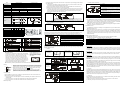
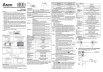
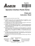
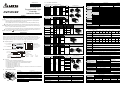
2006-07-04
5011634301-YIE1
http://www.delta.com.tw/industrialautomation/
Programmable Logic
Controller
Instruction Sheet
DVP-ES/EX
1
WARNING
This Installation Sheet only provides descriptions for electrical specifications, function specifications,
installation & wiring, troubleshooting and peripherals. Other detail infromation about programming and
instructions, please see PLC Application Manual. For more information about the optional peripherals,
please refer to their individual instruction sheet or user manuals.
This is an OPEN TYPE PLC. The PLC should be kept in an enclosure away from airborne dust, high
humidity, electric shock risk and vibration. Also, it should be equipped with protective methods such as
some special tools or keys to open the enclosure, so as to avoid the hazard to users and the damage to
the PLC.
The power must be OFF before any maintenance.
Never connect the AC main circuit power supply to any of the input/output terminals, as it will damage the
2.3.
DVP-ES/EX Series Models
◎ ES Standard Main Processing Units (MPU-00)
Input Unit
Output Unit
Model Name
Power
Point
Type
Point
Type
DVP14ES00R2
DVP24ES00R2
DVP32ES00R2
DVP40ES00R2
DVP60ES00R2
DVP14ES00T2
DVP24ES00T2
DVP32ES00T2
DVP40ES00T2
DVP60ES00T2
.
2
DVP14ES01R2
DVP24ES01R2
DVP24ES11R2
DVP32ES01R2
DVP14ES01T2
DVP24ES01T2
DVP32ES01T2
2.1.
Model Name Explanation and Peripherals
Thank you very much for purchasing Delta’s DVP-ES/EX Series PLC. DVP-ES/EX Series provide the main
processing units and extension units. The processing units offer 14~60 points and the extension units offer 8~32
DVP20EX00R2
100~
240
VAC
Barcode and Serial Number
MCU Version
T
5
Production series
100~240Vac 50/60Hz 35VA MAX
Production week
2.0A 240Vac 50/60Hz RES LOAD
Production year (2005)
Production plant (Taoyuan)
32ES00R2T5140004
VX.XX
Serial number of version
Production Model
DVP24XP00T
DVP
2 : Advanced Type
Models
E : Main Processing Unit (MPU)
X : Extension Unit
Model Type
S : Standard
X : A/D, D/A Functions
C : Non-extended
M : Digital Input
N : Digital Output
P : Digital Input/Output
R : Relay
T : Transistor
N : No Output Module
00 :
01 :
AC Input
DC Input
H TYPE
L TYPE
11 :
DC Input
H TYPE
Peripherals
◎ DVP-HPP Series: Handheld Programmable Panel
◎ WPLSoft: DVP-PLC Programming Software Tool (Windows based software)
◎ DVPACAB115: 1.5M Cable (HPP
PLC, provided in DVP-HPP Series)
◎ DVPACAB215: 1.5M Cable (PC
PLC)
◎ DVPACAB230: 3.0M Cable (PC
PLC)
◎ DVPACAB315: 1.5M Cable (HPP
PC)
◎ DVPACAB403: 30cm Cable (Main processing unit
Extension unit, or Extension unit
signal extension cable)
2.2.
1. DIN rail clip
4
Transistor
Timers
Profile
Data Registers
Relay
Pointers
Index Registers
Transistor
Constants
6
2
Relay
6
2
Transistor
6
2
Relay
DC
Sink
or
Source
16
0
16
8
0~20mA
or
0~10V
0
16
0
24
DC
Sink
or
Source
16
16
0
8
24
DVP24XP01T
16
8
DVP32XP01T
16
16
DVP08XM11N
8
0
DVP16XM11N
16
0
DVP08XN11R
0
8
DVP16XN11R
0
16
DVP24XN11R
0
24
4
DVP32XP11R
16
16
DC
Sink
or
Source
4
Profile Reference
Relay
Transistor
Profile Reference
None
2. DIN rail (35mm)
3. Direct mounting holes
11. Input / Output terminal cover
Grounding
Environment
Vibration / Shock
Resistance
Weight (g)
Transistor
Profile Reference
None
Relay
DVP16XN11T
0
16
6. Input / Output terminals
7. Input / Output terminals
8. Input / Output indicators
13. Input / Output terminal nameplate
panel
14. Input / Output terminal nameplate
panel
DVP24XN11T
0
24
DVP08XP11T
4
4
DVP24XP11T
16
8
DVP32XP11T
16
16
15. RS-485 communication port
I/O Processing Method
DVP60ES00
□
DVP20EX00
□
DVPDVPDVPDVP14ES01
32ES01
24ES□□
20EX11□
□
□
24VDC (-15%~10%)
Maximum power loss time is 5ms or less.
2 A / 250VAC
20 VA
25VA
30VA
30VA
35VA
30 VA
5.5 W
6.5 W
8W
8W
400mA
400mA
400mA
400mA
400mA
400mA
—
—
—
—
DC24V output short circuit
DC24V input polarity
1500VAC(Primary-secondary), 1500VAC(Primary-PE), 500VAC(Secondary-PE)
> 5 MΩ at 500VDC (Between all inputs / outputs and earth)
ESD: 8KV Air Discharge
EFT: Power Line: 2KV, Digital I/O: 1KV, Analog & Communication I/O: 250V
RS: 26MHz~1GHz, 10V/m
The diameter of grounding wire cannot be smaller than the wire diameter of terminals L and N (All DVP units
should be grounded directly to the ground pole).
Operation: 0°C ~55°C (Temperature), 50~95% (Humidity), Pollution degree2; Storage: -25°C ~70°C
(Temperature), 5~95% (Humidity)
Standard: IEC1131-2, IEC 68-2-6(TEST Fc)/ IEC1131-2 & IEC 68-2-27 (TEST Ea)
400
552
580
596
750
536
260
414
430
386
Input Point Electrical Specifications
Input Point Type
Input Type
Digital Input
DC (SINK or SOURCE)
Input Current
24VDC 5mA
Active Level
(Analog input resolution)
Reaction Time
(Conversion Sampling Time)
Off→On
above 16VDC
On→Off
below 14.4VDC
Analog Input (EX)
Voltage input: -10V~+10V, Input Resistance:
112KΩ
Current input: -20mA~+20mA, Input
Resistance: 250Ω
Voltage input: 10bit
Current input: 10 bit
About 10ms (An adjustment range of 0~15ms
could be selected through D1020 and D1021)
5ms (Time could be adjusted through D1118)
Output Point Electrical Specifications
Transistor
Relay-R
Current Specification
2A/1 point (5A/COM)
Voltage Specification
Below 250VAC, 30VDC
Specifications
Stored program, cyclic scan system
Batch processing (when END instruction
is executed)
Execution Speed
Basic commands (several us)
Program Language
Instruction, Ladder Logic, SFC
Remarks
I/O refresh instruction is available
Application instructions
(10 ~ hundreds us)
Including Step instructions
9W/1 point
90 W (Resistive)
Reaction Time
3.3.
Transistor-T
55°C 0.1A/1point, 50°C 0.15A/1 point
45°C 0.2A/1 point, 40°C 0.3A/1 point (2A/COM)
30VDC
75VA (Inductive)
Maximum Load
Function Specifications
Control Method
DVP40ES00
□
100~240VAC (-15%~10%), 50/60Hz ± 5%
Output Point Type
SPECIFICATIONS
Items
DVP32ES00
□
The PLC start to operate at power supply of 95~100VAC.
If the voltage of power supply drops to 70VAC, the PLC will stop.
Maximum power loss time is 10ms or less.
2 A / 250VAC
8
4. Communication Ports Cover (RS-232C) 12. Input / Output terminal cover
5. Extension Port indicators
DVP24ES00
□
16
0
3.1.
Fuse
Power
Consumption
DC24V Supply
Current
Power
Protection
Voltage
Withstand
Insulation
Resistance
Relay
8
DVP08XN11T
3
Operation
Specification
Noise Immunity
9. Input / Output
10. Status indicators: POWER, RUN, and
ERROR
DVP14ES00
□
Power Supply
Voltage
◎ Digital I/O Extension Unit for DVP-ES/EX Series-11 (H TYPE)
Input Unit
Output Unit
Profile
Model Name
Power
Point Type Point
Type
24
VDC
Model
16
0
Electrical Specifications
Item
16
DVP24XN01T
General
Latched
High Speed
General
Latched
Special
P
E/F
Decimal K
Hexadecimal H
Protection Features
Monitor / Debug
3.2.
16
DVP24XN01R
107 application instructions
* Note: For more information about special relays and data registers, please refer to the Delta PLC Application Manual.
24
DVP16XN01R
24
VDC
Profile Reference
Remarks
Built-in EEPROM
S0~S9
S10~S19
S20~S127
M0~M511+M768~M999
M512~M767
M1000~M1279
T0~T63 (100 ms time base)
T64~T126 (10 ms time base, when
63 points
M1028 is ON)
1 points
T127 (1 ms time base)
112 points
C0~C111
16 points
C112~C127
13 points 1 phase 20KHz, 2 phase 5KHz C235~C254 (all latched type)
408 points
D0 ~ D407
192 points
D408~D599
D1000~D1143、D1256~D1311
200 points
64 points
P0~P63
E(=D1028),F(=D1029)
2 points
16 bit: -32768~+32767
32 bit: -2147483648~+2147483647
16 bit: 0000~FFFF
32 bit: 00000000~FFFFFFFF
2 Ports is provided. RS-232C: Program read/write communication port,
RS-485: General function communication port (controlled by RS instruction);
Special drive instructions for Delta AC drive are also supported.
Password, I/O examination, Execution time, Illegitimate instruction or operand
Program execution time display, Bit/Word, Device setting
Serial Communication
16
8
Initial Step Point
Zero Return Point
General Step Point
General
Latched
Special
Digital
Counters
24
0
DVP24XP11R
Product Profile and Outline
8
DC Sink
or
Source
16
DVP08XP11R
Extension I/O
4
DVP16XM01N
DVP16XN01T
2
Auxiliary
Relays
-20mA~20
mA
or
-10V ~ +10
V
Specifications
3792 Steps
32 basic sequential instructions
(including STL / RET)
10 points
10 points
108 points
512+232 points
256 points
280 points
64 points
Instructions
Relay
◎ Digital I/O Extension Unit for DVP-ES/EX Series- 01 (L TYPE)
Input Unit
Output Unit
Model Name
Power
Profile
Point Type Point
Type
DVP32XP01R
Product Series
Points (Input + Output)
8
16
DVP24XP01R
Model/Serial Number Explanation
4
16
100~
240
VAC
DVP32XP00T
14 0004
8
0
DVP24XP00R
various applications according to input and output points, power supply, digital input and output modules.
PLC Model
Input Power Supply Spec.
Output Module Spec.
24
VDC
DVP24XN00R
DVP24XN00T
2
DC Sink
or
Source
Profile Reference
Step Relays
(Latched)
◎ Digital I/O Extension Unit for DVP-ES/EX Series- 00
Input Unit
Output Unit
Model Name
Power
Point Type Point
Type
DVP32XP00R
32ES00R
6
8
8
16
6
8
16
Profile
◎ EX Special Function Main Processing Units (MPU-00, MPU-11)
Input Unit
Output Unit
Model Name
Power Point
Type
Point
Type
DI AI
DI
AI
DO AO
DO
AO
points. The maximum input and output can be extended up to 128 points respectively. Also, it can be used on
Nameplate Explanation
DC Sink
or
Source
8
16
16
16
8
16
16
24
VDC
DVP20EX11R2
INTRODUCTION
6
8
16
16
24
6
8
16
16
24
◎ ES Standard Main Processing Units (MPU-01,11)
Input Unit
Output Unit
Model Name
Power
Point
Type
Point
Type
DVP20EX00T2
Do NOT touch terminals when power on.
8
16
16
24
36
8
16
16
24
36
100~
240
VAC
PLC. Check all the wiring prior to power up. To avoid any electromagnetic noise, make sure the PLC is
properly grounded
Items
Program Capacity
Off→On 20us On→Off 30us
About 10 ms
AD/DA Specifications
Items
Analog I/O Range
Digital Conversion
Range
Resolution
Input Impedance
Analog Input (A/D)
Voltage Input
Current Input
Analog Output (D/A)
Voltage Output
Current Output
±10V
±20 mA
0 ~ 10V
0 ~ 20 mA
-512~+511
-512~+511
0 ~ 255
0 ~ 255
10 bits(1LSB=19.53125 mV) 10 bits (1LSB=39.0625 μA) 8 bits(1LSB=39.0625 mV) 8 bits (1LSB=78.125 μA)
> 112 KΩ
250Ω
-
Items
Analog Input (A/D)
Voltage Input
Current Input
Analog Output (D/A)
Voltage Output
Current Output
-
0.5Ωor lower
Output Impedance
Tolerance Carried
Impedance
1KΩ~2MΩ
-
0~500Ω
Non-linear accuracy: ±0.5% of full scale within the range of PLC operation temperature
Overall Accuracy
Maximum deviation: ±1% of full scale at 20mA and +10V
Reaction Time
Absolute Input
Range
Digital Data Format
Average Function
Isolation Method
2ms × channels
±15 V
±32 mA
-
2’s complementary of 16-bit, 10 Significant Bits
2’s complementary of 16-bit, 8 Significant Bits
Provided
-
L
External Wiring
Diagram
Grounding
28K
CH3
I+
CH1
X1
I28K
2
3
3
5
INSTALLATION & WIRING
24VDC
OV
+24V 24G
H1
W
W1
W2
W3
(H Type) (L Type)
95
99
104
82
50
DVP24ES00(01)[11]R2/T2 100
95
150
155
82
50
DC/DC
H
DVP32ES00(01)[11]R2/T2 100
95
150
155
82
50
DVP40ES00R2/T2
100
95
150
155
82
-
DVP60ES00[11]R2/T2
90
89.6
-
DVP20EX00[11]R2/T2
100
82
-
85.5 180.5 185
95
150
155
H1
DVP14ES00(01)[11]R2/T2 100
W2
W1
W
W3
2. The “LOW V.” LED on the Expansion Unit is an indication that the input power voltage is insufficient, thus all
outputs of the expansion unit should be turned off.
Operation and Test
5
1
S/S X4
X5 X6 X7
X0 X1 X2 X3
S/S X4 X5 X6 X7 C0 Y2 C1 Y5
X0 X1 X2 X3 Y0 Y1 Y3 Y4
00
01
( DC Power IN, DC Signal IN )
20EX
( AC Power IN, DC Signal IN )
Y0 Y1
C0 C1
00
MC
( AC Power IN, DC Signal IN )
3
MC
1
S/S
S/S X10 X11 X12 X13 X14 X15 X16 X17
X0 X1 X2 X3 X4 X5 X6 X7
00
01
( DC Power IN, DC Signal IN )
40ES
11
( DC Power IN, DC Signal IN )
2
Guard
Limit
Y0 Y1 Y2 Y3 Y4
C0 C1 C2 C3 Y5
S/S
S/S
X2
1. If the ERROR LED of the MPU is not blinking, use the peripheral device to give the RUN command, and the
RUN indicator will then be on.
( AC Power IN, DC Signal IN )
Y2
Y0
Y1
C0 C1
Y2 Y3
C2 C3
Y4 Y5
C4 C5
Y6 Y7
C6 C7
24VDC
S/S X10 X11 X12 X13 X14 X15 X16 X17
X0 X1 X2 X3 X4 X5 X6 X7
01
( DC Power IN, DC Signal IN )
Y0 Y1
C0 Y2
Y4
Y3
60ES
C0 Y1 Y3 Y4 Y6 C2 Y11 Y13 Y14 Y16
Y0 Y2 C1 Y5 Y7 Y10 Y12 C3 Y15 Y17
L
OV
N
6
7
6
00
( AC Power IN, DC Signal IN )
Y0
Y1
C0 Y2
Y4 Y5
Y3 C1 Y6
Y10 Y11
Y14 Y15
Y7 C2 Y12 Y13 C3 Y16 Y17
PLC Input/Output Reaction Time:
Emergency stop: PLC must provide a quick manual method to
disconnect all system power.
Circuit isolation device (System Power Disconnect): Utilize the
electromagnetic contactor and the relay to be the isolation unit of the
power circuit to prevent the possible instability of the system when the
power is supplied on and off.
DVP PLC MPU (main processing unit)
Grounding resistance: 100Ω or less
Power supply: AC: 100~240VAC, 50/60Hz, DC: 24VDC
00
Y0 Y1 Y2 Y3 Y4 Y5
C0 C1 C2 C3 C4 Y6
Y10 Y11
Y14 Y15
Y20 Y21
Y24 Y25
Y7 C5 Y12 Y13 C6 Y16 Y17 C7 Y22 Y23 C8 Y26 Y27
PLC Mounting Arrangements and Installation Notes
DIN Rail Installation
The DVP-PLC can be secured to a cabinet by using the DIN rail that
is 35mm high with a depth of 7.5mm. When mounting the PLC on the
DIN rail, ensure to use the end bracket to stop any side-to-side
motion of the PLC, thus to reduce the chance of the wires being
pulled loose. On the bottom of the PLC is a small retaining clip. To
secure the PLC to the DIN rail, place it onto the rail and gently push
up on the clip. To remove it, use a slotted screwdriver, place it on the
groove of the retaining clip and press gently, then pull down on the
retaining clip and gently pull the PLC away from the DIN rail.
For heat dissipation,ensure to
provide a minimum clearance of
50mm between the unit and all
sides of the cabinet. (as the figure
shown below)
◎ Definition
Sink = Current flows
into the common
terminal S/S
Source = Current
flows out of the
common terminal S/S
S/S
Sinking
X0
X0
> 50mm
Direct mounting : Use the specified dimensions and install with M4 screws.
DC Type
(DC Signal IN)
To suit M3.5 screw terminals
Below 6.2
SINK
24G
If the ERROR LED is blinking swiftly, it suggests that the +24VDC power supply of the PLC is insufficient. Please
check whether the power supply of 24VDC is normal or not.
S/S
X0
+24V
24G
SINK Mode
Power Input Wiring
X0
X1
X2
When the ERROR LED is on (not blinking), it indicates that the execution time of the program loop has exceeded
the time-out setting (set by D1000). Please check the program loop or use ”WDT” instruction to solve the problem.
When the ERROR LED is on, please power down the MPU and start up it one time, and then check if the RUN
LED is off. If the RUN LED is not off, please check if there is any noise and interference and check if any
conductive material falling into the PLC.
Wiring Loop
SOURCE
+24V
DC Type
(DC Signal IN)
+5V
24VDC
24G
S/S
+24V
X0
SOURCE Mode
24G
S/S
X0
X1
X2
Source Type
◎ Practical Relay Output Wiring
Surge absorbing diode: increases relay contact life
Emergency stop: use an external switch
Fuse: use the fuse with a 5~10A capacity at the common end of the output
contact to protect the output circuit.
Surge absorber: reduces noise on AC inductive loads
5
C0 Y0 Y1
2
1. Do not mount the PLC in a location subjected to corrosive or flammable gases, liquids, or airborne dust or
metallic particles.
2. Do not mount the PLC in a location where temperatures and humidity will exceed specification.
3. Do not mount the PLC in a location where vibration and shock will exceed specification.
S/S
Sink Type
Installation Notes
Incorrect installation may result in a PLC malfunction or premature failure of the PLC. Ensure to observe the
following items when selecting a mounting location.
There is a “POWER” LED at the front of the MPU. The “POWER” LED will be lit (in green) when the power in
connected to MPU. If the indicator is not on when the MPU is powered up and with the input power being normal,
it indicates that the PLC is out of order. Please have this machine replaced or repaired at a distributor near you.
If an incorrect program is input to the MPU, or the instruction and the device exceed the allowable range, the
indicator will blink. At this moment, the user should check the error code saved in the MPU data register D1004 to
correct the program. Find out the cause of the error and modify the programs. Then, re-send the correct program
to the MPU.
Wiring Loop
+5V
24VDC
Wiring
Below 6.2
☼ “POWER” LED
☼ “ERROR” LED
Input Point Loop Equivalent Circuit
1. Please use O-type or Y-type terminals for I/O wiring terminals. The specification for the
terminals is shown as the figure on the left. PLC terminal screws should be tightened
to between 5~8 kg-cm (4.3~6.9 in-lbs). Only can use 60/75°C copper conducting wire.
2. DO NOT wire to the No Function terminals ‧ . I/O signal wires or power supply
should not run through the same multi-wire cable or conduit.
3. When tightening the screws and performing the wiring, please avoid that metallic
particles fell into PLC. After completing wiring, please remove the label which is used
to obstruct the metallic particles on the ventilation hole for well heat dissipation.
TROUBLESHOOTING
Identify the status of the PLC. When the PLC is in operation, this light will be on, and the user could thus use HPP
or the editing program of the ladder diagram to give commands to make the PLC “RUN” or “STOP”.
◎ Wiring
+24V
> 50mm
6
Default 10ms. Please refer to the usage of special registers D1020~D1021.
Please refer to the usage of special register D1010.
Relay module: 10ms. Transistor module: 20~30us.
☼ PLC “RUN” LED
S/S
Input Point Loop Equivalent Circuit
DVP MPU
Input delay time
Program scan time
Output delay time
Sourcing
> 50mm
> 50mm
The total reaction time from the input signal to the output operation is calculated as follows:
Reaction Time = input delay time + program scan time + output delay time
udge the errors by the indicators on the front panel. When errors occurred on DVP series PLC, please check:
The input signal of the input point is the DC power DC input. There are two types of DC type wiring: SINK and
SOURCE, defined as follows:
( AC Power IN, DC Signal IN )
2. HPP could be utilized to monitor the timer (T), the counter (C) and the data register (D) during operation, and
moreover, to force the output contacts to conduct the On/Off action. If the ERROR LED is on (but not blinking),
it indicates that the setting of the user’s program has exceeded the preset overtime limit, thus users have to
double check the program and perform the On/Off function again. (The PLC is at this moment back to STOP
status automatically).
Power supply for AC loads
Fuse for circuit protection (3A Limit)
Power On pilot indicator
Input Point Wiring
S/S X22 X23 X24 X25 X26 X27 X30 X31 X32 X33 X34 X35 X36 X37 X40 X41 X42 X43
X0 X1 X2 X3 X4 X5 X6 X7 X10 X11 X12 X13 X14 X15 X16 X17 X20 X21
X0 X2 X4 X6 X10 X12 X14 X16 X20 X22 X24 X26
X1 X3 X5 X7 X11 X13 X15 X17 X21 X23 X25 X27
( AC Power IN, DC Signal IN )
32ES
5V
Since the PLC is in control of numerous devices, operation of either one device could affect the operation of other
devices, therefore the breakdown of either one device would consequently be detrimental to the whole auto
control system, and danger will thus be resulted. Please use the recommended wiring below for the power input:
8
Y0 Y1
C0 C1
X1
Safety Wiring
4
S/S X4
X0
24ES
X0
DVP
Terminal Wiring
14ES
S/S
2.5A
H
TRIAL RUN
1. The “POWER” LED at the front of the MPU or the Extension Units will be lit (in green) if the power is on. If the
indicator is not on when the MPU is powered up, it means that there is abnormal condition on the DC power
supply of the PLC. It is thus necessary to check the wiring on terminals +24V and 0V. If the ERROR LED is
blinking swiftly, it indicates that the +24V power supply of the PLC is insufficient.
20VDC~26VDC
Dimensions
Model Name (mm)
MC2
5V
DC Input Type
4
MC1
X2
5. When DC voltage is supplied to the PLC, ensure the power is at terminals 24VDC and 0V (power range is
20.4VDC~26.4VDC). When the voltage is lower than 17.5VDC, PLC will stop operating, all outputs will turn
OFF and the ERROR LED will flash continuously.
I-
250
Grounding
S/S X0
The +24V supply output is rated at 0.4A from MPU. DO NOT connect external power supply to this
terminal. Moreover, it takes 5~7mA to drive each input point, so total of 100mA is needed for 16 input
points. As a result, the output loads of +24V should not exceeds 300mA.
AC Drive
56K
I+
7
Y7
Power Indication
V-
CH0
6
1
V+
CH0
Current Input
-20mA~+20mA
24G
DC/DC
V-
Grounding
N
2.0A
56K
6
Unused terminal: do not connect
damage and current output break.
V+
5
Y1 C1 Y4 Y5 Y6
DC supply
Emergency stop
Fuse for circuit protection
As all outputs of the transistor modules are Open Collectors, if the setting of
Y0 is pulse train output (using PLSY command), its pull-up resistor must
remain an output current of greater than 0.1A for normal operation of the
transistor modules.
As all outputs of the transistor modules are Open Collectors, if the setting of
Y1 is pulse train output (using PWM command), its pull-up resistor must
remain an output current of greater than 0.1A for normal operation of the
transistor modules.
Mutually exclusive outputs: use external hardware interlocks, as well as
those in the PLC program, for maximum safety.
100~240VAC
Voltage output has short circuit protection but a long period of short circuit may cause internal wire
Voltage Input
-10V~+10V
4
C0 Y0
AC Input Type
Isolation between digital area and analog area. But no isolation among channels.
Protection
◎ Practical Transistor Output Wiring
There are two power inputs provided in DVP series PLC, AC input and DC input. Please pay particular attention
to the following notes:
1. Connect the AC input (100VAC~240VAC) to terminals L and N. Any AC110V or AC220V connected to the
+24V terminal or input points will permanently damage the PLC.
2. The AC power inputs for the MPU and the I/O Expansion Unit should be ON or OFF at the same time.
3. Please use wires of 1.6mm or above for the grounding of the MPU.
4. If the power-cut time is less than 10ms, the PLC still operates unaffectedly. If the power-cut time is too long
or the power voltage drops, the PLC will stop operating and all the outputs will be OFF. Once the power is
restored, the PLC will return to operate automatically. (There are latched auxiliary relays and registers
inside of the PLC, please be aware when programming.)
3
6
C1 Y4 Y5 Y6
Y7
9
1
3
MC1
MC2
Unused terminal: do not connect
10
2
8
4
7
DC supply
Indicator: neon indicator
AC supply
Incandescent lamp (resistive loading)
Mutually exclusive outputs: use external hardware interlocks, as well as
those in the PLC program, for maximum safety.
☼ “Input” LED
The On/Off signals of the input point could be displayed through the “Input” LED. Also, the status signal of the
input point could be monitored through the device monitoring function of HPP. As long as the input point is
activated, the LED is on. Therefore, if an error is detected, please check HPP, the LED indicator and the input
signal circuits. Please pay particular attention to check if an electrical switch with significant leakage current is
used as it often results in the unexpected operation of input point.
☼ “Output” LED
Output LED indicates if the output signals are on or off. Please check the following items when the LED On/Off
indication does not correspond to the commands:
1. Output contacts may be melted and stuck together due to a short circuit or current overload.
2. Check wiring and verify that the screws are tight and secure.