Transcript
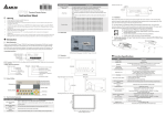
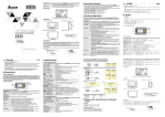
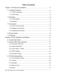
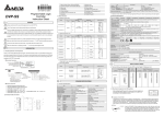
V X.XX
DELTA ELECTRONICS, INC
MADE IN XXXXXXX
Alarm Indication LED
RS-232 Indication LED
RS-485 Indication LED
TP04G
ON PC (RS-232)
+24V
0V
Escape/Exit
Enter key
5
1
6
1
5
RX
TX
Function Keys
6
9
9 PIN D-SUB
9 PIN D-SUB
Shift Key
97.00
[3.82]
ON TP04G
9
RS-485
Arrow keys
PC
+
LCM
Display Area
Functional Specification
MODEL
TP04G-AS1
ITEM
Screen
STN-LCD
Color
Monochromatic
The back-light automatic turn off time is 1~99 minutes
(0 = do not to turn off)
Back-light
(back-light life is about 50 thousand hours at 25℃)
Resolution
128X64 dots
Display Range
67 mm (W) X 32 mm (H), 3” diagonal preferred
Contrast
10-step contrast adjustment
Adjustment
ASCII: characters (including European Fonts)
Taiwan: (BIG 5 code) traditional Chinese character font
Language Font
China: (GB2324-80 code) simplified Chinese character
font
Font Size(ASCII)
5 X 8, 8 X 8, 8 X 12, 8 X 16
5 X 8: 25 words X 8 rows
Maximum words
8 X 8: 16 words X 8 rows
x rows, for each
8 X 12: 16 words X 5 rows
font size
8 X 16: 16 words X 4 rows
1. Power on indication (Flash three times)
ALARM
2. Flash for communication error or other alarm
Indication LED
3. Special Indication by user programming
RS-232 Indication
It will be flashing when transmitting program and
LED (Yellow)
communicating by using RS-232.
RS-485 Indication
It will be flashing when communicating by using RS-485.
LED (Green)
Program Memory
256KB flash memory
Unsynchronized transmission method: RS-232
Serial
Data length: 7 or 8 bits
Communication
Stop bits: 1or 2 bits
(COM1)
Parity: None/Odd/Even
Transmission speed: 9600bps~115200bps
Unsynchronized transmission method: RS-485
Extension
Data length: 7 or 8 bits
Communication
Stop bits: 1 or 2 bits
port
Parity: None/Odd/Even
(COM2)
Transmission speed: 9600bps~115200bps
Extension Slot
1. Update program version 2.The slot for program copy
card
Battery Cover
DC 3V battery for HMI
5-pin terminal
There are DC 24V input and RS-485 input
Communication Connection
TP04G may connect to a PC by using connection cable
DVPACAB530
Display Screen
Copy HMI program to PCC
Copy program in PCC to HMI
(TP PCC)
(PCC TP)
Turn the switch on the PCC to
Turn the switch on the PCC to
1
TP PCC
PCC TP
Insert the PCC into the extension
Insert the PCC into the extension
2
slot of TP
slot of TP
3
Input the power to TP
Input the power to TP
It will display “remove PCC” on the It will display “remove PCC” on the
Panel Function
4
TP04G-AS1
screen and power on again
screen and power on again
Component
Explanation
HMI Display Message
Instruction Sheet Alarm Indication Status 1: When power is on, the LED will flash slowly.
Copy PCC program to HMI
Status 2: When there is an abnormal situation, the LED will
Warning
LED
Copy HMI program to PCC (TP PCC)
(PCC TP)
flash quickly along with an alarm sound.
Always read this manual thoroughly before using the TP04G.
RS-232 Indication Will flash when transmitting program and communicating
If the model type of TP does not
If there is no program in PCC, TP
DANGER! DC input power must be OFF before any maintenance. Do
LED (Yellow)
by using RS-232.
correspond with the model type of program will display “The PCC is Empty
not connect or remove wires and connectors while power up to the circuit.
of PCC, TP will display “TP series and
PCC TP series is illegal”.
RS-485 Indication Will flash when communicating by using RS-485.
Only the qualified technicians are allowed to do the maintenance.
PCC is different Press Enter to Confirm
LED (Green)
The display panel of the TP04G is waterproof. But please keep away
TP series PCC Press Esc to Exit”.
LCM display Area Liquid Crystal Module display area.
grease, corrosive liquids or sharp objects from contacting the TP04G.
TP will display “TP PCC series Please TP will display “PCC TP series
Used to cancel an incorrect input, or to Exit a programming
Esc
(Escape/Exit)
DANGER! The TP04G requires 24VDC input power. The 24VDC input
wait !” during transmission.
Please wait !” during transmission.
step.
power should not be connected to the RS-485 communication port. The
TP will display “Please Remove the PCC TP will display “Please Remove
UP/Pg Up: Used to increase the value or move screen one
unit may be destroyed and can’t be repaired if the input power is
and Reboot” when completing transmitting. the PCC and Reboot” when
page up.
incorrectly applied. Please confirm the input power wiring is correct
completing transmitting.
Pg Dn/DOWN: Used to decrease the value or move screen
Arrow Keys
before power up.
Hardware Operation
one page down.
DANGER! An electrical charge will remain on the DC-link capacitors for 1
The steps to Startup the TP04G:
Left: Left direction key. (move curser to left)
minute after power has been removed. This residual power may be
1. Connect power line,
Right: Right direction key. (move cursor to right)
hazardous and the TP04G should not be worked on until this charge has
2. Apply 24V DC power,
Shift Key
Used to select keys F5, F6, F7, F8, F9.
dissipated. To prevent personal injury, do not conduct any wiring or
3. Enter into the startup display,
F0/F5: used to be a constant 0 (F0), or 5 (Shift + F0) when
investigation on the TP04G until 1 minute after power off.
4. Enter the user-designed program
they are in system menu. User can define the functions
CAUTION! Always ground the TP04G using the grounding terminal. Not
5. Press ESC key and hold on for 5 seconds to return to system menu.
separately when they are in user page.
only will this act as a safety, but help to filter out electrical noise. The
There are five selections in the system menu and are described below.
F1/F6: used to be a constant 1 (F1), or 6 (Shift + F1) when
grounding method must comply with the laws of the country where the
Use the connection cable (DVPACAB530) to connect the serial
they are in system menu. User can define the functions
Download
unit is to be installed.
communication port RS-232 of TP04 to a PC. Then use the
separately when they are in user page.
Program
CAUTION! If you turn the fixed support that is packaged together with
TPEdit software to download an application program to the TP04.
F2/F7: used to be a constant 2 (F2), or 7 (Shift + F2) when
TP04G too tight, TP04G may be damaged.
Use the connection cable (DVPACAB530) to connect the serial
Function Keys
they are in system menu. User can define the functions
Upload
communication port RS-232 of TP04 to a PC. Then use the
separately when they are in user page.
Nameplate
Program
TPEdit software to upload an application program from the TP04.
F3/F8: used to be a constant 3 (F3), or 8 (Shift + F3) when
Operation Panel
Production model
Transfer a program between two TP04 units.
they
are
in
system
menu.
User
can
define
the
functions
MODEL :
TP04G-AS1
Power input Spec.
POWER INPUT :
24VDC 3.5W
1: transmit programs
separately when they are in user page.
Barcode and
serial number
2: receive programs
F4/F9: used to be a constant 4 (F4), or 9 (Shift + F4) when
Version
Copy
TP04GAS1T318002
When transmitting programs and data between two TP04 units.
they are in system menu. User can define the functions
Program
Set one TP04 to “Receive Program” mode and the other TP04 to
separately when they are in user page.
Note: The words of “MADE IN XXXXX” will be different due to the
“Transmit Program” mode. Please use twisted pair wires to
manufacturing location.
Enter key
Used to input a value or accept a programming command.
connect the two units via the RS-485 ports.
Electrical Specification
Model Explanation
Serial Number Explanation
There are 8 items that used to modify TP04 system settings:
TP04GAS 1 T 3 18 002
TP 04 G - AS 1
MODEL
TP04G-AS1
Production serial number
ITEM
Reserved
1. Communication protocol: Setting the address of TP04, the
Production weeks
Reserved
Production year (2003)
control port, and the communication string for either RS-232 or
Function Key/Digital Key F0~F4, ESC, SHIFT, ENTER and ARROW keys
T: Text mode
T: Taoyuan
Production factory
G: Graphic mode
RS-485.
External Input Power
24V (3.5W Max.)
LCD Spec.
Version
Series name
Production model
2. Contrast: Adjust the contrast of LCM display screen.
Memory Capacity
256K Byte
3. Back-light: adjust the automatic turn off time of LCM.
CPU
16 bits
Outline
Back Panel
Factory setting is 01, setting range is 00~99 seconds. If set to
RAM of System
32K Byte
Battery
00, the LCM Back-light will not turn off.
RS-232
Communication
Cover
Com1: RS-232 and Com2: RS-485
4. Date and Time: It is used to set the TP04 built-in RTC including
Interface
year, month, day, hour, minute, second and week. Also the
Waterproof Class of
Extension Slot
TP04
IP65/NEMA4
internal battery capacity display is shown here.
Front Panel
Settings
5. Buzzer: Used to set the buzzer sound, normal mode or quiet
0~50℃, relative humidity 20-90% RH
Temperature for
mode.
Dimensions (Unit: mm)
Hardware
(non-condensing)
6. Language Setting: Used to set the displayed language.
Front Panel
Right Side Diagram
Storage Temperature of
English, Traditional Chinese, simplified Chinese or user
-20~60℃
Hardware
defined language.
0.5mm displacement, 10-55Hz, X, Y, Z three
7. Password setting: Used to set, enable, and disable the
Vibration
directions and two hours for each direction
85.00
password function. If the password function is enabled, user
[3.35]
10G, 11ms, from X, Y, Z three directions and three
then needs to input a password before the system menu may
Impact
times for each direction
be accessed. The factory password is 1234.
Radiated Emission
CISPR22, Class A
8. Startup display: Used to select the TP04 startup display.
Electrostatic Discharge
Vertical View
Execute the internal program. When entering execution
EN61000-4-2/1995
Immunity
Execution program, you can return to system menu by pressing Escape/Exit
Radiated Immunity
EN61000-4-3/1995
(Esc) key for 5 seconds.
Electrical Fast
There are two methods to connect to PLC:
EN61000-4-4/1995
Transient
1. Use the connection cable (DVPACAB215 or DVPACAB230)
PLC
to connect program communication I/O RS-232C of PLC to
0.24kg / 147×97×35.5mm
Back Panel
Mounting Panel Dimension
Weight / Dimension
Connection serial communication port (COM1) RS-232 of TP04.
(Weight(W)×Height(H)×Deep(D))
2. Use twisted cable to connect RS-485 of PLC to extension
Cooling Method
Natural air-cooling
communication port (COM2) RS-485.
The Function of Program Copy Card
Function of program copy card TP04G provides to copy user program, system Password Functions
function and passwords is different from the regular copy program. It is used to 1. If user forgot the password, password then can be cleared via using the
following code: 8888. This universal code will clear the password and all
copy the whole HMI environment settings and application programs to another
TP04 internal programs. The TP04 will be reset to the factory settings.
HMI rapidly. It saves time and manpower. The operation is as follows.
Installation Method
2. Users may use 0~9 and A~Z as characters for the password. Users
Definition: program copy card PCC, TP Series TP.
One easy way is insert TP04G to the opening hole of panel and tight up the
must use the function keys F0~F4 to input the password characters.
screws. However, if a firm mounting TP04G to the panel is needed, please use
F0: scrolls in a loop as follows 0
5 A B
C
D
E
F
0
the fixed support accessory which is packed together with TP04G, then infix the
F1: scrolls in a loop as follows 1
6
G
H
I
J
K
1
fixed support in the back and tight up the screws.
F2: scrolls in a loop as follows 2
7
L M
N
O
P
2
F3: scrolls in a loop as follows 3
8
Q
R
S
T
U
V 3
If you turn the screw exceeds torque: 4-5(kg-cm), TP04G may be damaged.
F4: scrolls in a loop as follows 4
9
W
X Y
Z
4
Operation Interface Panels Series
Step
External Interface
Thickness:
0.5~9.0mm
1
2
3
4
5
6
7
8
9
1
2
3
4
5
6
7
8
9
GND
RX
TX
TP04G may connect to the DVP-PLC by using cable DVPACAB215
(1.5 m) or DVPACAB230 (3.0 m without 25 pin D-SUB).
PC or TP04G
PLC(DVPACAB215)
13
8 PIN MINI DIN
ON PLC
25 PIN D-SUB
147.00 [5.79]
135~136.5[5.31~5.37]
Thickness Range 0.5~9mm
1
9
5
6
1
9 PIN D-SUB
PC or TP04G end
25 PIN D-SUB
Socket
Pin 2:TX
Pin 3:RX
Pin 7:GND
9 PIN D-SUB
Socket
Pin 2:RX
Pin 3:TX
Pin 5:GND
6
8
20
4
5
7
2
3
1
2
3
4
5
6
7
8
9
ON PLC
8 PIN MINI DIN
GND
TX
RX
8
4
5
2 1
5 4 3
8
7 6
85
[3.35]
14
Pin 1,2:5V
Pin 3,6,8:GND
Pin 4:RX
Pin 5:TX
Pin 7:+24V