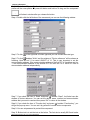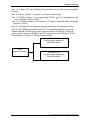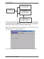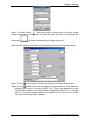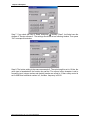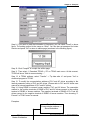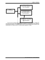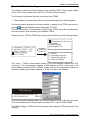
1
Table of Contents
Chapter 1 Overview and Installation ............................................................... 1-1
1-1 Hardware Features ............................................................................. 1-1
1-1-1 TP04G Components...................................................................................... 1-1
1-1-2 TP04G Keys .................................................................................................. 1-2
1-2 Mounting ............................................................................................. 1-4
1-2-1 Panel Opening............................................................................................... 1-3
1-2-2 Mounting........................................................................................................ 1-4
1-3 Connection.......................................................................................... 1-4
1-3-1 One-To-One Connection ............................................................................... 1-4
1-3-2 Multiple Link Connection ............................................................................... 1-4
1-3-3 Programming Connection.............................................................................. 1-5
1-4 Power Supply ...................................................................................... 1-5
1-5 Cleaning.............................................................................................. 1-5
Chapter 2 TP04G Operation and Settings ...................................................... 2-1
2-1 System Main Menu ............................................................................. 2-1
2-2 System Main Menu Operation............................................................. 2-1
2-2-1 Download TP04G!PC.................................................................................. 2-1
2-2-2 Upload TP04G"PC ...................................................................................... 2-2
2-2-3 Copy TP04G<-->TP04G................................................................................ 2-3
2-2-4 TP04G Settings ............................................................................................. 2-4
2-2-5 Execution Program ........................................................................................ 2-4
2-3 TP04G Settings Menu......................................................................... 2-4
2-3-1 Communication Protocol ............................................................................... 2-4
2-3-2 Contrast......................................................................................................... 2-6
2-3-3 Back-light....................................................................................................... 2-6
2-3-4 Date and Time............................................................................................... 2-7
2-3-5 Buzzer ........................................................................................................... 2-7
DELTA ELECTRONICS, INC. ALL RIGHTS RESERVED
i
Content
2-3-6 Language Settings ........................................................................................ 2-8
2-3-7 Password Settings......................................................................................... 2-8
2-3-8 Start-up Display............................................................................................. 2-9
Chapter 3 TPEdit Operation............................................................................ 3-1
3-1 Hardware ............................................................................................ 3-1
3-2 Installation........................................................................................... 3-1
3-3 Basic Introduction ............................................................................... 3-4
3-4 Skills for mouse operation................................................................... 3-4
3-5 TPEdit software windows .................................................................... 3-5
3-5-1 Explanation.................................................................................................... 3-5
3-5-2 Menu Bar Overview....................................................................................... 3-6
3-6 TPEdit Software Explanation in Detail .............................................. 3-12
3-6-1 File .............................................................................................................. 3-12
3-6-2 Edit .............................................................................................................. 3-19
3-6-3 Compile ....................................................................................................... 3-23
3-6-4 Objects Function Explanation...................................................................... 3-24
3-6-5 View............................................................................................................. 3-40
3-6-6 Transfer ....................................................................................................... 3-40
3-6-7 Settings ....................................................................................................... 3-41
3-6-8 Windows...................................................................................................... 3-42
3-6-9 Help ............................................................................................................. 3-42
Chapter 4 Communication Connection Mode ................................................. 4-1
Chapter 5 Examples ....................................................................................... 5-1
Chapter 6 Troubleshooting ............................................................................. 6-1
DELTA ELECTRONICS, INC. ALL RIGHTS RESERVED
ii
Preface
Preface
The TP series is a small HMI (human machine interface) with big features. It allows
users to monitor and control PLCs, Variable Frequency Drives, and other controllers. The
TP series may also be purchased with graphic capabilities (TP--G models). The TP series
products are programmed using the TPEdit software.
Getting Started
Users should read the entire manual before using the TPEdit software or TP series
hardware.
It is not recommended to use a button on the TP series product as an emergency
stop button. The TP series is powered by external power. If power is lost, the
emergency stop button will not work.
TP Series Hardware Introduction
Please refer to the information packaged with unit for details regarding dimensions
and specification of all TP models.
TP04G features:
Dimension: 140*90*27.5(mm)
Keypad: thin-film keypad with 5 user-defined function keys and 7 control keys.
Function keys: F0/F5, F1/F6, F2/F7, F3/F8 and F4/F9.
Control keys: Esc, Shift, Up/PgUp, Down/PgDn, Left, Right
Keystroke Life: Five hundred thousand. The keystroke life may
decrease due to environment (such as corrosive liquids or gas), object
used to depress keys, and the pressure used to depress the keys.
Display:
!
!
!
!
!
!
!
!
!
!
!
!
Monochromatic LCM, yellow-green back-light TFT
Resolution: 128X64 dots
Display dimensions: 66.5mm x 33.2mm (w x h)
Adjustable contrast
CPU: 16-bit
FLASH: 256K Bytes for user information
SRAM: 32K Bytes for system information
Communication Interface: RS232 (9Pin D-sub) and RS485
RTC with perpetual calendar (year, month, day, hour, minute, second,
week)
DELTA ELECTRONICS, INC. ALL RIGHTS RESERVED
Chapter 1 Overview and Installation
Chapter 1 Overview and Installation
Features of TP04G:
!
!
!
!
!
!
!
Monitoring programming and controlling PLCs, AC drives or other controllers.
There are three built in languages to choose from (Traditional Chinese, Simplified
Chinese and English, the factory setting is English).
Built-in RS232 and RS485 communication ports.
Built-in RTC with perpetual calendar function.
Display has auto power off energy saving function.
Password functions for system operation and program safety.
Very Bright back-light LCD display:
1-1 Hardware Features
1-1-1 TP04G Components
Alarm indication
LED
LCM
display area
Arrow keys
Escape/Exit
Enter key
Shift key
Function keys
TP04G Profile
1-1
DELTA ELECTRONICS, INC. ALL RIGHTS RESERVED
Chapter 1 Overview and Installation
Chart 1-1 Explanation of TP04G components
Back Panel
Front Panel
Components
Explanation
Display area of
A 128*64 resolution of yellow-green back-light LCD (Liquid
Text and graphics Crystal Display).
LED
Standard LED functions: power on indication,
communication indication, and a user-defined indication.
Status 1: When power is on, LED will start blinking slowly.
Status 2: When it is abnormal, LED will light every second
along with the audible alarm.
RS232
communication
port
A 9 pin D-sub connector. It is used to upload and
download programs to a PC or PLC (or other
communication device). For the Delta PLC, use a
DVPACAB215 (TP#PLC / 2.5m) cable between this port
and the PLC.
RS485
communication
port
A 2-wire RS485 fixed terminal. It is used to upload and
download programs to a PC or PLC (or other
communication device). This communication port is used
when connecting multiple TP series units.
Power input
terminal
Supply a 24VDC supply to this point.
Extension Port
Used to connect external function cards and update the
BIOS.
TP04G Keypad information
The keystroke life of the waterproof MYLAR keypad is five hundred
thousand depressions. The life may decrease due to environmental issues
(such as corrosive liquid or gas), devices used to depress the keys, and the
pressure used to depress keys.
1-1-2 TP04G Keys
There are 12 keys total: 7 command keys and 5 user-defined function keys.
Command keys: Esc, Shift, Enter, Up/PgUp, PgDn/Down, Left, Right
Function keys: F0/F5, F1/F6, F2/F7, F3/F8, F4/F9
Chart 1-2 Explanations for command keys
1-2
DELTA ELECTRONICS, INC. ALL RIGHTS RESERVED
Chapter 1 Overview and Installation
Command key
Button
Explanation
ENTER
Used to enter new data or confirm a message
ESC
Used to change the mode between user program
mode and system menu mode. Also to escape an
incorrect entry.
UP ARROW
Up key may be used to increase a value or to
move to the upper page.
DOWN ARROW
Down key may be used to decrease a value or to
move to the lower page.
LEFT ARROW
Left key is used to choose the decimal place of a
number.
RIGHT ARROW
Right key is used to choose the decimal place of a
number.
SHIFT
It is the shift key when using function keys F0 ~ F9
and other keys.
Chart 1-3 Explanations for function keys
Function
keys
Button
Explanation
F0/F5
Function 0 (F0) or 5 (Shift+F0) in the system menu. Users
may define its function during programming.
F1/F6
Function 1 (F1) or 6 (Shift+F1) in the system menu. Users
may define its function during programming.
F2/F7
Function 2 (F2) or 7 (Shift+F2) in the system menu. Users
may define its function during programming.
F3/F8
Function 3 (F3) or 8 (Shift+F3) in the system menu. Users
may define its function during programming.
F4/F9
Function 4 (F4) or 9 (Shift+F4) in the system menu. Users
may define its function during programming.
1-2 TP04G Mounting
1-2-1 Panel Opening
The cut out for the TP04G must be 85.5mm x 137.5mm and the range of thickness
should be between 1.0~4.0mm.
1-3
DELTA ELECTRONICS, INC. ALL RIGHTS RESERVED
Chapter 1 Overview and Installation
1-2-2 Mounting
Mounting TP04G into the opening is done by carefully fitting the unit into the
opening and pressing firmly on all four corners.
Thickness:1.0〜4.0mm
1-3 Connection
The TP04G may connect to a Delta DVP-PLC via a DVPACAB215 cable (Note 1). It
may also connect to other PLCs or AC drives using a user supplied cable. The TP
series may connect to more than one device using the 2-wire RS485 connection.
1-3-1 One-To-One Connection
When one PLC connects to a TP04G, the TP04G should be set to one-to-one
communication.
Figure 1
1-3-2 Multiple Link Connection
When many PLCs are connected to one TP04G or many TP04Gs are connected
together, the TP04G should be set to multiple link. Please refer to appendix B for detail.
The factory setting of communication address of TP04G is 1. Users may change
the “TP04 address” in system menu. All other communication settings may also be
updated in the system menu.
Figure 2
1-4
DELTA ELECTRONICS, INC. ALL RIGHTS RESERVED
Chapter 1 Overview and Installation
1-3-3 Programming Connection
The TP04G may use the RS232 or RS485 to connect to a PC.
recommended connection is using the RS232 port and a DVPACAB215 cable.
The
1-4 Power connection
TP04G requires a 24VDC at 150mA power source for operation. Proper grounding
is required to filter any electrical noise and make sure the hardware components work
normally.
1-5 Cleaning
When cleaning the TP04G, please use soft cotton cloth and water. For stubborn
marks, a cleaning liquid may be used, but try a small section to verify it will not damage the
Mylar cover.
1-5
DELTA ELECTRONICS, INC. ALL RIGHTS RESERVED
Chapter 2 TP04G Operation and Settings
Chapter 2
TP04G Operation and Settings
This chapter will introduce the two working modes of the TP04G:
! System main menu mode: users can change the settings of the HMI using five
main menus. This chapter will discuss the content and function of each menu,
and teach you how to use the TP04G.
! Display monitor mode: this will display on screen status of devices connected to
the TP04G (ex: PLC, AC drives or other hardware devices). User can use the
TPEdit software to create the type of monitoring needed of each external piece of
hardware.
2-1 System Main Menu
When TP04G is powered on, it will display “Delta” and then “TP04G”. User may enter the
system main menu by pressing and holding the “Esc” key on the front panel at the same
time the TP04G is displayed. Continue to hold until the System Menu appears.
There are five selections in the System Main Menu as shown below:
1. Download TP04G <-- PC
2. Upload TP04G --> PC
3. Copy TP04G <--> PC
4. TP04G Settings
5. Execute
You can choose any of the options by pressing the “Up” or “Down” key on the front panel
and then pressing the “Enter” key. If an error is made, you may press the “Esc” key to
exit and return to the System Main Menu screen.
2-2 Operation
2-2-1 Download TP04G <--PC
! Allows the user to download a program from a PC to the TP04G. After choosing
option 1, the TP04G will wait for the PC (TPEdit software) to send data. As the
data is being received the TP04G will display a receive status on the screen.
Once all the data is received, you may return to the System Main Menu by
pressing the “Esc” key.
! Below is a pictorial description of the process.
1. Download TP04G <-- PC
2. Upload TP04G --> PC
3. Copy TP04G <--> PC
4. TP04G Settings
5. Execute
ENTER
Waiting for Communicating...
! If the communication is abnormal, such as a time-out, the display below will be
shown on the TP04G.
2-1
DELTA ELECTRONICS, INC. ALL RIGHTS RESERVED
Chapter 2 TP04G Operation and Settings
Waiting for Communicating...
Time Out
Esc : Escape Enter : Retry
! The following display is shown when the communication is complete.
Communication is Completed.
Esc : Escape
2-2-2 Upload TP04G -->PC
Allows the user to send a program from the TP04G to the PC for reviewing or updating.
After choosing option 2, the TP04G will wait for the PC (TPEdit software) to send a
ready message and then the TP04G will display the data receive status bar during
communication. Once all the data is received, you may return to the System Main Menu
by pressing the “Esc” key.
Below is a pictorial description of the process.
1. Download TP04G <-- PC
2 . Upload TP04G --> PC
3. Copy TP04G <--> PC
4. TP04G Settings
5. Execute
ENTER
Waiting for Communicating...
! If the communication is abnormal, such as a time-out, the display below will be
shown on the TP04G.
Waiting for Communicating...
Time Out
Esc : Escape Enter : Retry
! The following display is shown when communication is complete.
Communication is Completed.
Esc : Escape
DELTA ELECTRONICS, INC. ALL RIGHTS RESERVED
2-2
Chapter 2 TP04G Operation and Settings
2-2-3 Copy TP04G <-->TP04G
! The Copy function allows the user to move a program from on TP04G to another
TP04G via communication. Connection must be done, using twisted pair wire
connected between two TP04G RS485 communication ports.
! Below is a pictorial description of the process.
1. Download TP04G <-- PC
2. Upload TP04G --> PC
3 . Copy TP04G <--> PC
4. TP04G Settings
5. Execute
ENTER
1. Transmit Program
2. Receive Program
! Users must select which TP04G will receive the program and then select which
TP04G will transmit the program. Once the option to Transmit is selected the
Tpo4G will begin communication, therefore always do this step last. During the
transmission a progress display will be shown as below.
1. Transmit Program
2. Receive Program
ENTER
Waiting for Communicating...
1. Transmit Program
2 . Receive Program
! If the communication is abnormal, such as a time-out, the display below will be
shown on the TP04G.
Waiting for Communicating...
Time Out
Esc : Escape Enter : Retry
! The following display is shown when communication is complete.
Communication is Completed.
Esc : Escape
2-3
DELTA ELECTRONICS, INC. ALL RIGHTS RESERVED
Chapter 2 TP04G Operation and Settings
2-2-4 TP04G Settings
! When choosing option 4 “TP04G Settings”, there will be two displays (8 total
options) to choose for set up.
1. Download TP04G <-- PC
2. Upload TP04G --> PC
3. Copy TP04G <--> PC
4 . TP04G Settings
5. Execute
1. Communication Protocol
2. Contrast
3. Back-lighted
4. Date and Time
ENTER
5. Buzzer
6. Language Settings
7. Password Settings
8. Start-up Display
! Please refer to section 3 for details of the TP04G set-up menu.
2-2-5 Execute program
! Choosing the Execute mode, causes the TP series product to leave the System
Menu and begin monitoring your connected components.
1. Download TP04G <-- PC
2. Upload TP04G --> PC
3. Copy TP04G <--> PC
4. TP04G Settings
5 . Execute
ENTER
0
25
50
75
100
Display T0 Counter Value
! Before entering the monitor mode, the TP series product will display the start-up
window “TP04G”. Once the TP04G disappears, the monitor mode is active and
the TP series product will use the users created program.
! Users may use the TPEdit software to customize the start-up display.
2-3 TP04G Settings Menu
After entering the TP04G settings menu, the user is given 8 options to choose from.
The programming of each of these 8 options, are described below.
2-3-1 Communication Protocol.
1. Communication Protocol
2. Contrast
3. Back-lighted
4. Date and Time
ENTER
Communication Protocol
1. TP04G Settings
2. RS232
3. RS485
A. TP04G Communication Protocol
! Select option 1 “TP04G Settings” and the following display will appear.
DELTA ELECTRONICS, INC. ALL RIGHTS RESERVED
2-4
Chapter 2 TP04G Operation and Settings
Communication Protocol
1. TP04G Settings
2. RS232
3. RS485
TP04G Settings
ENTER
1. Communication address 001
2. PLC Control Port
RS232
! Communication Address: Users may use the left, right, F0-F4 and Shift F0-F4
keys to change the value of communication address. The left and right keys are
used to choose the integer location, and the F0-F4 keys are used to select a
value of the integer. Example: if F2 is pressed, a value of 2 is placed in the
integer location the curser is displaying. The address may be set from 0~255. If
the value set exceeds this range, the unit will reset the address to 001. After the
Communication Address has been set, press the “Esc” key to go back to the
TP04G settings screen.
! PLC Control Port: Users may choose RS232 or RS485 as the control port. To
set the PLC control port, use the Left or Right arrow to toggle between RS232 or
RS485 and press Enter.
TP04G Settings
ENTER
TP04G Settings
1. Communication address 001
2. PLC Control Port
RS485
1. Communication address 001
2 . PLC Control Port
RS232
B. RS232
! The RS232 Protocol parameters may be set to meet the needs of the connected
hardware. The Transmission Baud rate, Data Length, Parity check, and Stop Bit
are all programmable using the Left and Right arrows and scrolling through the
available options.
Communication Protocol
1. TP04G Settings
2 . RS232
3. RS485
ENTER
RS232
1. Transmission Rate
2. Data Length
3. Parity Check
4. Stop Bit
9600
7-bit
Even
1-bit
! Transmission Rate: The Left or Right arrow will scroll from 9600 to 19200 or
38400. When complete press the Enter key.
RS232
1. Transmission Rate
2. Data Length
3. Parity Check
4. Stop Bit
9600
7-bit
Even
1-bit
ENTER
<
RS232
1. Transmission Rate
2. Data Length
3. Parity Check
4. Stop Bit
! Data Length: The Left or Right arrow will toggle between 7-bit or 8 bit.
complete press the Enter key.
2-5
>
19200
7-bit
Even
1-bit
When
DELTA ELECTRONICS, INC. ALL RIGHTS RESERVED
Chapter 2 TP04G Operation and Settings
RS232
1. Transmission Rate
2 . Data Length
3. Parity Check
4. Stop Bit
9600
7-bit
Even
1-bit
ENTER
<
RS232
1. Transmission Rate
2. Data Length
3. Parity Check
4. Stop Bit
! Parity Check: The Left or Right arrow will scroll from Even to None, Odd.
complete press the Enter key.
RS232
1. Transmission Rate
2. Data Length
3 . Parity Check
4. Stop Bit
9600
7-bit
Even
1-bit
ENTER
<
RS232
1. Transmission Rate
2. Data Length
3. Parity Check
4. Stop Bit
! Stop bit: The Left or Right arrow will toggle between 1-bit or 2-bit.
complete press the Enter key.
RS232
1. Transmission Rate
2. Data Length
3. Parity Check
4 . Stop Bit
9600
7-bit
Even
1-bit
ENTER
<
RS232
1. Transmission Rate
2. Data Length
3. Parity Check
4. Stop Bit
>
9600
7-bit
Even
1-bit
When
>
9600
7-bit
Odd
1-bit
When
>
9600
7-bit
Even
1-bit
C. RS485
The process of setting the RS485 protocol, are the same as the RS232. Please refer
to the above procedures for setting this communication port.
2-3-2 Contrast
! To change the contrast of the display, select option “2. Contrast” and use the Left
and Right arrows to move the bar graph. When complete press the enter key.
1. Communication Protocol
2 . Contrast
3. Back-lighted
4. Date and Time
Contrast
ENTER
- <
> +
2-3-3 Back-light
! Editing the Back Light auto off time: Use the Left and Right arrows to choose the
digit and the Function keys (F0-F4) to choose the value of time in minutes. When
complete press the Enter key.
DELTA ELECTRONICS, INC. ALL RIGHTS RESERVED
2-6
Chapter 2 TP04G Operation and Settings
1. Communication Protocol
2. Contrast
3 . Back-lighted
4. Date and Time
ENTER
Back-lighted
Auto Close
05 minutes
! The factory setting is 01 minute. The available range is 00~99 minutes. A
setting of 00 will cause the Back Light to never turn off.
2-3-4 Date and Time
1. Communication Protocol
2. Contrast
3. Back-lighted
4 . Date and Time
ENTER
Date and Time
1. Date
2003/01/10
2. Day
FRI
3. Time
17:55:27
Battery Capacity
! Editing the Date: Use the left and Right arrows to move the curser to the correct
digit. Use the F0-F4 keys to change the value of the digit. When complete press
the Enter key.
Date and Time
1. Date
2003/01/10
2. Day
FRI
3. Time
17:55:27
Battery Capacity
ENTER
Date and Time
1. Date
2003/01/ 1 0
2. Day
FRI
3. Time
17:55:27
Battery Capacity
! Editing the Day: Use the Left and Right arrows to scroll through the days of the
week. Press the Enter key when the correct day is found. When complete press
the Enter key.
Date and Time
1. Date
2003/01/10
2 . Day
FRI
3. Time
17:55:27
Battery Capacity
ENTER
Date and Time
1. Date
2003/01/10
FRI
2. Day
3. Time
17:55:27
Battery Capacity
! Editing the Time: Use the Left and Right arrows to choose a digit and the F0-F4
keys to select a value for each digit. When complete press the Enter key.
Date and Time
1. Date
2003/01/10
2. Day
FRI
3 . Time
17:55:27
Battery Capacity
ENTER
Date and Time
1. Date
2003/01/10
2. Day
FRI
3. Time
17:5 7 :27
Battery Capacity
2-3-5 Buzzer
2-7
DELTA ELECTRONICS, INC. ALL RIGHTS RESERVED
Chapter 2 TP04G Operation and Settings
5. Buzzer
6. Language Settings
7. Password Settings
8. Start-up Display
Buzzer
ENTER
1. Normal
2. Mute
! Use the Up or Down arrow to choose Normal or Mute.
the Enter key.
2-3-6
When complete press
Language Settings
5. Buzzer
6 . Language Settings
7. Password Settings
8. Start-up Display
Language Settings
ENTER
1. English
2. Traditional Chinese
3. Simplified Chinese
4. User-defined
! You can select a language by using the UP or Down keys.
may be entered using the TPEdit software program.
Other languages
2-3-7 Password Settings
5. Buzzer
6. Language Settings
7 . Password Settings
8. Start-up Display
Password Settings
ENTER
1. New Password
2. Enable
No
! You can set a password by using the Left and Right arrow keys for the digit and
the F0~F4 keys for the value. After completing your password, press the Enter
key to save it or press the Esc key to cancel the entry.
Password Settings
1. New Password
2. Enable
No
Input Password
ENTER
1234
Esc : Escape Enter : Retry
F0/F5
Cycle through 0, 5, A, B, C, D, E, F
F1/F6
Cycle through 1, 6, G, H, I, J, K
F2/F7
Cycle through 2, 7, L, M, N, O, P
F3/F8
Cycle through 3, 8, Q, R, S, T, U, V
F4/F9
Cycle through 4, 9, W, X, Y, Z
! The password may be generated using numbers and letters. Each time the
function key is pressed a new number or letter is shown as the sequence above
describes.
DELTA ELECTRONICS, INC. ALL RIGHTS RESERVED
2-8
Chapter 2 TP04G Operation and Settings
2-3-8 Start-up Display
5. Buzzer
6. Language Settings
7. Password Settings
8 . Start-up Display
Start-up Display
ENTER
1. TP04G Settings
2. User-defined
! TP04G settings are the factory default display.
! The User defined settings are based on the display created in the TPEdit
software.
2-9
DELTA ELECTRONICS, INC. ALL RIGHTS RESERVED
Chapter 3 TPEdit Software Operation
Chapter 3 TPEdit Software Operation
3-1 Hardware requirement
Operation system requirement for installing TPEdit should be:
Items
Operation system
CPU
Memory
Hard disk capacity
Display resolution
Mouse
Printer
RS-232
System requirement
Windows 95/98/2000/NT/XP
Pentium 90 or above
16MB or above (32MB and above is recommended)
20MB or above
640x480, 16 colors and above
Compatible with Windows
Compatible with Windows
At least one Com Port to connect to TP04G
3-2 Installation
! Start-up Windows
! Put the TPEdit software CD into disk
! Press【Start】to select Run
! Select the installation disk and directory to save.
3-1
DELTA ELECTRONICS, INC. ALL RIGHTS RESERVED
Chapter 3 TPEdit Software Operation
! Press Next> for following steps to go to next step
! Enter user name and company name.
User name
Company name
DELTA ELECTRONICS, INC. ALL RIGHTS RESERVED
3-2
Chapter 3 TPEdit Software Operation
Press Next> to go to the following window for installing.
3-3
DELTA ELECTRONICS, INC. ALL RIGHTS RESERVED
Chapter 3 TPEdit Software Operation
After finishing installing, user can execute TPEdit from windows> start.
3-3 Basic Introduction
TPEdit is the program editor for DELTA PLC series use in WINDOWS. You can see
the design result on the screen immediately by concept of “What You See is What You
Get” that TPEdit adopts. What you see on the screen is what display on HMI. TPEdit
uses object-oriented method to reach drag edition. In this way, you can move the
components to anywhere and change shapes and sizes by using mouse. It is very easy
for you to use this software.
3-4 Skills for Mouse Operation
In the window, you can operate with either keyboard or mouse. But it will be easier
to operate with mouse.
There are four main operation functions in Windows:
! One click left-button: to select function or component item.
! Double-click left-button: to enter or execute the item.
! Drag: press and hold on the left button to drag the mouse to move or adjust size.
Once you release the button, the operation is finished. It is used to move or
adjust size.
! One click right button: it will display a pop-up menu of editing operation for you to
select.
It is usually to show mouse pointer on the screen to let you know where the position you
are. There are many shapes of mouse to mean the different situation. You can know the
edition status by the mouse pointer.
DELTA ELECTRONICS, INC. ALL RIGHTS RESERVED
3-4
Chapter 3 TPEdit Software Operation
Mouse Pointer
Name
Arrow pointer
!、"
Resize pointer
!
I
Cross pointer
I pointer
Functions
The position where the mouse is.
It will display on the border of windows or object
when adjusting size.
It will display when opening object or drawing.
It will display when editing text.
3-5 TPEdit Software Window
3-5-1 Explanation
Display name bar
Menu bar
Function Toolbar
Object Toolbar
Geometric Toolbar
Working area
Status Bar
! Display Name Bar: display the present file name and file directory.
! Menu Bar: There are 9 functions (File, Edit, Compile, Object, View, Transfer,
Setting, Windows and Help) in the menu bar.
! Function Toolbar: you can click the button what you want to execute directly with
mouse. It is very easy for those users that are not familiar with computer to
operate.
! Object Toolbar: you can click the button what you want to execute directly with
mouse.
! Geometric Toolbar: it provides an easy drawing system in display plan for user to
edit HMI display directly.
! Working Area: it is the area for editing. That is also the display that will show on
HMI screen.
! Status Bar: it is used to display the desired object name and geometric
coordinate.
3-5
DELTA ELECTRONICS, INC. ALL RIGHTS RESERVED
Chapter 3 TPEdit Software Operation
The start-up display of TPEdit will be shown as follows. There are four functions in
menu bar for you to select.
After opening file, you should set machine setting, including PLC or Inverter type, TP
type and file name. At the moment, you can select other functions in menu bar. We
will introduce them later.
3-5-2 Menu Bar Overview
File (F)
DELTA ELECTRONICS, INC. ALL RIGHTS RESERVED
3-6
Chapter 3 TPEdit Software Operation
! Create a new project
! Open an old project
! User Menu Set: users can set the languages or menu depends on requirement.
! Save: save the file into disk.
! Save as: save the present file to other file name.
! Print: print present file and set printer settings.
! Close Project: close present project.
! Exit: exit TPEdit.
Edit(E)
! Add new page
! Jump page: input the jump page condition. If the condition is held, it will jump to
the designated page.
! Function key setting: it is used to define the functions and button types of function
keys F0~F9.
! Alarm setting: input alarm condition. When the condition is held, buzzer sounds.
! Warning LED setting: input alarm condition. When the condition is held, warning
LED will light.
! Save image of pages: save the present page to clip board or file.
3-7
DELTA ELECTRONICS, INC. ALL RIGHTS RESERVED
Chapter 3 TPEdit Software Operation
! Undo: back to the previous condition.
! Redo: do the condition before redo. (this item is for future edition)
! Delete: delete the component in editing page.
! Cut: delete and cut the component in editing page.
! Copy: copy the component in editing page.
! Paste: paste the component to editing page.
! Select all: select all components in editing page.
User could one-click right button of mouse to get pop-up menu to edit every
component quickly, such as copy, paste, move and etc.
Edit
! Compile: to compile the finished page to download to TP04G.
Object:
DELTA ELECTRONICS, INC. ALL RIGHTS RESERVED
3-8
Chapter 3 TPEdit Software Operation
! Static Text: edit text to shown on TP04G screen.
! Value Show: HMI reads PLC corresponding value of register to show on HMI
screen.
! Bit Light: HMI reads the corresponding contacts (ON or OFF) or register data to
show the corresponding figures on HMI screen.
! Figure: it is used to edit static figure to be the background. Or it also could be
used for HMI to read the corresponding contacts (ON or OFF) or register data to
show the corresponding dynamic figures on HMI screen.
! Scale: edit the scale that user needs to HMI screen.
! Bar Chart: HMI reads the PLC corresponding data of register to convert to bar
chart to show on HMI screen.
! Meter: HMI reads PLC corresponding data of register to convert to circle meter to
show on HMI screen.
! Message Show: HMI reads PLC corresponding contacts (ON or OFF) or register
data to show the corresponding message on HMI screen.
! Button: it will have a series of button type for you to choose. It will be easier to
design PLC program.
! Perpetual Calendar: HMI reads time, week, date of PLC to show on HMI screen.
! Geometry: it is used to edit HMI display.
! Lamp Display: HMI reads the corresponding contacts (ON or OFF) or register
data to show the corresponding user-defined figure or characters on HMI screen.
! Measure Unit: edit the unit that user needs on HMI screen.
View:
3-9
DELTA ELECTRONICS, INC. ALL RIGHTS RESERVED
Chapter 3 TPEdit Software Operation
! Tpe Page Manager: manage the edited page.
! Tpe Page: display edited HMI page and switch between HMI page and start-up
display.
! Starting Figure: edit start-up display and switch between HMI page and start-up
display.
Transfer
! Tp data read out: Read application program from TP04G to TPEdit.
! Tp data write in: Write application program from TPEdit to TP04G.
! Starting figure write in: input start-up display that edited by TPEdit into TP04G.
! User menu write in: input user-defined user menu into TP04G.
Settings:
! IDE Font: it is used to set the font attributes that used in TPEdit.
! Communication Protocol: it is used to set communication format.
! Page Size: it is used to set windows’ size.
! Frame Settings: it is used to set using grid or not.
! System page jump: when the conditions are held, it will jump to the designated
page. This is used for system to change page. It is not necessary to set change
condition for each page. Once the condition in each page is held, it will jump to
the designated page. (if the conditions of system change page conflicts with the
DELTA ELECTRONICS, INC. ALL RIGHTS RESERVED
3-10
Chapter 3 TPEdit Software Operation
conditions of each page, the conditions of each page has high priority.)
! System Funkey set: it is used to define the button type and functions of function
keys F0~F9. It doesn’t need to set in each page. Once the function keys F0~F9
are used, they will be executed according to the definition of button type and
functions. (if the function settings of system conflicts with the function settings of
each page, the function setting of each page has high priority.)
! System Alarm: to set system alarm condition. When the conditions are held,
buzzer will sound. It doesn’t need to set condition in each page. Once the
condition is held, buzzer will sound in any page. (if the system alarm condition
conflicts with the alarm condition of each page, the alarm condition of each page
has high priority.
! System LED: to input alarm condition. When the condition is held, HMI alarm LED
will light. It doesn’t need to input alarm condition in each page. (if the alarm
condition conflicts with alarm condition of each page, the alarm condition of each
page has high priority.)
3-11
DELTA ELECTRONICS, INC. ALL RIGHTS RESERVED
Chapter 3 TPEdit Software Operation
Windows:
! Tile Vert.: display edit page in vertical.
! Tile Horz.: display edit page in horizontal.
! Cascade: display edit page in overlay.
Help:
! Version: display software version of TPEdit and relative information.
! Tpe Help: provide electronic file of TPEdit user manual.
Above is the basic introduction of TPEdit. We will explain the functions that used
frequently for detail in the following.
3-6 TPEdit Software Explanation in Detail
3-6-1 File
! Create a New Project
It is used to create a new project. Do one of the following:
Method 1:
Step 1. File (F) > create a new project.
5 last used files
DELTA ELECTRONICS, INC. ALL RIGHTS RESERVED
3-12
Chapter 3 TPEdit Software Operation
Step 2. Enter machine type setting.
Step 3. User can set PLC or Inverter Type, TP type and File Name in this dialog box.
Step 4. You can use file name to record the function of program. For example, you
can name ”MonitorProductionLine” for the program that monitors the
production line.
Step 5. TPEdit document usually have extension .tpe. TPEdit will name your new
project to be Tpe0. (the default name will be Tpe0. tpe, Tpe1. tpe……in order.
The following is the window for creating new project.
Method 2: Click the button
to create a new project.
Method 3: Pressing〔Ctrl〕+〔N〕to create a new project.
! Open an Old Project
3-13
DELTA ELECTRONICS, INC. ALL RIGHTS RESERVED
Chapter 3 TPEdit Software Operation
Method 1:
Step 1. choose File (F) > Open an old project.
Step 2. Open an old project dialog box.
File name # key in or select the file name that you want to open. It will show all the
file type that selected in “file type” in this dialog box.
File type # select the file type you want to open: Tpe File (i.e. *.tpe)
Search # select the disk or file that you want open.
Method 2: Click the button
to open the existed file.
Method 3: Pressing〔Ctrl〕+〔O〕.
! User Menu Set
You can set the language, menu content or HMI information according to your request.
In addition to the default three languages, user can select the suitable language for
themselves. The following is for detail:
Step 1.
Choose File (F) > User Menu Set, and it will show 20 pages about user
menu setting for you to set.
DELTA ELECTRONICS, INC. ALL RIGHTS RESERVED
3-14
Chapter 3 TPEdit Software Operation
Step 2. You can set the language you need here. But you can’t modify the function
definition and button size.
Step 3. You just need to double-click the item you want to modify and it will show the
dialog box for you to edit.
3-15
DELTA ELECTRONICS, INC. ALL RIGHTS RESERVED
Chapter 3 TPEdit Software Operation
PC in TP04G hardware main
Step 4. After editing, press 1. download TP04G
menu. The words “Waiting for communicating…” will be shown on HMI screen.
Step 5. Choose Transfer(T) > Input User-defined Menu. This function just can be used
under the mode of setting user menu. It is used to download the menu to
TP04.
Step 6. To set language you should select 6. language setting in TP04G main menu
and then press Enter to set.
Language Settings
5. Buzzer
6 . Language Settings
7. Password Settings
8. Start-up Display
ENTER
! Save
It is used to save the present file into disk.
Method 1: choose File(F) > Save to save with the
original file name.
Method 2: Click the button
.
DELTA ELECTRONICS, INC. ALL RIGHTS RESERVED
3-16
1. English
2. Traditional Chinese
3. Simplified Chinese
4. User-defined
Chapter 3 TPEdit Software Operation
Method 3: Press〔Ctrl〕+〔S〕.
! Save as
Save the present file in another name into disk. TPEdit will save new project to be the
default name, if you want to save it to another name, please choose “Save as”.
Step 1. Choose File (F) > Save as.
Step 2. input file name and then save.
3-17
DELTA ELECTRONICS, INC. ALL RIGHTS RESERVED
Chapter 3 TPEdit Software Operation
! Print
Step 1. Choose File (F) >Print.
Step 2. You can check the print attribute you need in the following dialog box.
DELTA ELECTRONICS, INC. ALL RIGHTS RESERVED
3-18
Chapter 3 TPEdit Software Operation
! Close Project
Choose File (F) > Close Project to close the present project.
! Exit
Choose File (F) > Exit or click
not before exit TPEdit.
3-6-2
at the right upper-corner. Please confirm to save or
Edit (E)
In addition to undo, cute and paste functions of TPEdit, there are four functions
(including add new page, jump page, alarm setting, alarm LED setting) you can use.
We will explain these four functions in the following.
! Add New Page
Choose Edit (E) > Add New Page or click the button
to add new page.
! Jump Page
Step 1. Choose Edit (E) > Jump Page or click right mouse button directly in editing
page and select “Jump Page” in pop-up menu.
Pop-up menu for edit function
Working area
Step 2. After clicking, it will show “Jump Page Set” dialog box.
3-19
DELTA ELECTRONICS, INC. ALL RIGHTS RESERVED
Chapter 3 TPEdit Software Operation
Step 3. Click reference device to input device name, device number and
communication address. The devices’ name that you can set in this window
are X, Y, M, S, D, C and T and the equipment no. are 0~F.
Select the reference device (In the “Jump Page Set” dialog box, it is different to set Bit
or Value in condition Set. If you set to Bit, the device name you can select are X, Y, M,
S, C and T. If you set to Value, the device name you can select are T, C and D. In
dialog box of device reference, you can check device name and select device name
by clicking
. If it is AC drive, you don’t need to check device name. It will show $ to
mean absolute address of AC drive, input equipment no, communication address and
then press Enter to return to jump page set dialog box.
Step 4. In condition set, you could set Bit or Value. If you set it to Bit, it will jump to
designate page. If you set it to Value, you need to input value length, value
type, condition and operation condition. If the conditions are held, it will jump
to the designate page. If you just edit one page, the jump page will display 0
DELTA ELECTRONICS, INC. ALL RIGHTS RESERVED
3-20
Chapter 3 TPEdit Software Operation
due to the default first page is number 0.
You can set the value length and value type that you need in value setting.
Value length could be 16-bit or 32-bit. Value type could be unsigned or signed
decimal, hexadecimal or BCD. Condition could be =, <, >, >=, <= or !=.
Step 5. After finishing input, press “Add in” to add. The condition will display in the
message window. You can press “Update” to update jump page condition or
press “Delete”, “Delete All” to delete condition.
3-21
DELTA ELECTRONICS, INC. ALL RIGHTS RESERVED
Chapter 3 TPEdit Software Operation
Step 6. After setting, press “Close” to return to editing page.
! Function Key Settings
Step 1. Choose Edit (E) > Function Key Settings or click right button of mouse to get
the pop-up menu to select function key settings.
Step 2. And then you will get the following function key setting dialog box.
! Step 3. it is used to set button type of function key F0~F9. (you can refer to object
setting.) Once you set a function key, you should press button “Set” to set. And if
you want to clear a function key, you just need to select that function key and
press “Clear” to clear or press “Clear All” to clear all. After setting, you can press
“Close” to exit this dialog box.
! Alarm Setting
Step 1. Choose Edit (E) > Alarm Setting or click right button of mouse in editing page
to get pop-up menu to select alarm setting.
Step 2. And then you will get the alarm setting dialog box.
DELTA ELECTRONICS, INC. ALL RIGHTS RESERVED
3-22
Chapter 3 TPEdit Software Operation
Step 3. The settings are the same as jump page settings. When the condition is held,
buzzer will sound.
! Alarm LED Settings
The settings of alarm LED are the same as alarm settings. Once the condition is held,
the alarm LED will light.
! Save image of pages: Choose Edit (E) > Save image of pages to save the
present image to clipboard or file.
! Undo, Redo: to back to the previous action or redo the action before execute
“undo”.
! The functions of delete, Cut, Copy, Paste and Select all:
Delete: delete the component from editing page.
Cut: delete and cut the component from editing page.
Copy: copy the component from editing page.
Paste: paste the component from editing page.
Select all: select all components from editing page.
3-6-3 Compile
3-23
DELTA ELECTRONICS, INC. ALL RIGHTS RESERVED
Chapter 3 TPEdit Software Operation
Choose Compile (C) > Compile or click the button
to compile application program
to transmit to TP04G. After compiling successfully, you will get the following dialog
box.
3-6-4 Objects Function Explanation
You could choose Object (O) or press ﹝ ALT ﹞ + ﹝ O ﹞ to set object. It is the
management system for all objects. You need to open a page before using this
function.
DELTA ELECTRONICS, INC. ALL RIGHTS RESERVED
3-24
Chapter 3 TPEdit Software Operation
! Static Text
Step 1. Choose Object (O) > Static Text or click the button
. At the moment, the
mouse pointer will be cross pointer. You can press the left button of mouse,
drag to the position you need and then release to get the text square.
Step 2. Move the mouse to static text square and then double-click left button of
mouse to get the following window.
3-25
DELTA ELECTRONICS, INC. ALL RIGHTS RESERVED
Chapter 3 TPEdit Software Operation
Step 3. You can input text and setting the font attributes (including frame setting, text
direction, position and font type). Frame setting could be single frame, double
frames, bold frames, dotted line frames or spotted line frames. Text direction
could be from left towards to right, from right towards to left, from up towards
to down and from down towards to up. Text position could be left side, right
side or middle side. You could select the font you need by pressing the button
“Font type” and you will get the following dialog box.
Step 4. After setting, you will get the static text. If it can’t show completely, you should
enlarge the size of text square.
! Value Show
Step 1. Choose Object (O) > Value Show or click the button
dialog box.
DELTA ELECTRONICS, INC. ALL RIGHTS RESERVED
3-26
to get the following
Chapter 3 TPEdit Software Operation
Step 2. Click reference device and you will get the following window.
Step 3. In this dialog box, you could set device name to be T, C and D and device
number to be 0~F. If your device name is AC driver, it doesn’t need to check
device name. It will show symbol $ to mean AC driver absolute address. What
you need is to input absolute address in device number.
Step 4. You could set device name, value type, value length, position, integer number,
decimal number, frame setting, font, blink and fill 0 into upper bit.
Step 5. Value type could be unsigned decimal, signed decimal, hexadecimal, ASCII,
Binary or BCD code. Value length could be 16 bits or 32 bits. The position
could be right side, left side and middle.
Step 6. The digital numbers of integer and decimal according to the setting of display
value number. For example, if the real value of timer T0 is 50 seconds, if you
set integer number is 3 and decimal number is 0 and it will display 500. If you
set 3 for integer number and 1 for decimal number and it will display 050.0.
Step 7. The settings of frame could be no frame, double-line frame, bold frame and
the font size could be 5X8, 8X8, 8X12 and 8X16.
Step 8.You could choose to fill 0 in upper bit or not. For example, there are 6 integer
numbers and 2 decimal numbers of a value. If you check to fill 0, the value
324836 will display to 003248.36. If you don’t check to fill 0, the value 324836
will display to 3248.36.
3-27
DELTA ELECTRONICS, INC. ALL RIGHTS RESERVED
Chapter 3 TPEdit Software Operation
Step 9. After setting, HMI will read PLC corresponding reference device to show the
value on HMI screen.
! Bit Light
There are two types for you to choose:
State Show Setting: Choose Object (O) > Bit Light (16X16) > State Show or click the
button
to set. When HMI reads the PLC corresponding
contacts (ON or OFF), it will show the corresponding figure.
Range Light Setting: choose Object (O) > Bit Light (16X16) > Range Light or click the
to set. If you set as the following dialog box, When
button
the device value >= 300, base state is 0 and the figure will
.
display
DELTA ELECTRONICS, INC. ALL RIGHTS RESERVED
3-28
Chapter 3 TPEdit Software Operation
! Figure
You could choose static figure or dynamic figure.
Static Figure: choose Object (O) > Figure > Static figure or click the button
. It will
read the static figure to be the background of HMI. It just can read the
file with extension .bmp now.
Step 1. Choose Object (O) > Figure > Static figure and move the mouse to the editing
area. At the moment, the mouse pointer will be cross pointer. Pressing the
left button and hold on to drag, once you release the button the action will
be finished. The component
will be shown.
Step 2. Moving the mouse on this component and double-click the left button. You will
get the following pop-up dialog box.
Step 3. Click the button “BMP Read”, you will get the following open dialog box.
Choosing the picture with BMP file you want to open, and then click Open (O)
to return to Bmp | Text Setting dialog box. Then pressing OK to exit and the
picture you choose will display on the screen.
3-29
DELTA ELECTRONICS, INC. ALL RIGHTS RESERVED
Chapter 3 TPEdit Software Operation
TPEdit has built-in figures (including button type and arrows) for users to use.
The built-in figures are saved in TPEdit\ BmpGroup.
Dynamic Figure: Choose Object (O) > Figure > dynamic figure or click the button
.
HMI reads PLC corresponding reference register value will do
comparison operation according to the corresponding base state.
The setting figure will be displayed on the screen according to the
operation result. (it you check bit, base state could be 0 or 1. If you
check value, base state could be set to 255)
DELTA ELECTRONICS, INC. ALL RIGHTS RESERVED
3-30
Chapter 3 TPEdit Software Operation
Step 1. Choosing Object (O) > Figure > Dynamic figure and then move the mouse to
the editing area. At the moment, the mouse pointer will be cross pointer and
you could press left button and hold on to drag. Once you release the button,
the action will be finished and the component
will be displayed.
Step 2. You could move the mouse to this component and double-click the left button
to get the following dialog box.
Step 3. The settings of reference device, base state, range number are the same as
the range light setting. The base state could be set to 0~254. If you press
BMP read, you will get the open dialog box. You could set the corresponding
picture for the base state. Each base state has the corresponding range value,
if device value >= range value and it will show the corresponding picture. For
example, if base state 0 and range value is 100, base state 1 and range value
is 300, when device value is between 100, 300 and it will show the
corresponding picture of base state 0, if device value is large than 300, and it
will show the corresponding picture of base state 1. But if device value is small
than 100, it won’t display any picture due to no base state conforms to it.
! Scale
Step 1. Choose Object (O) > Scale or click the button
3-31
to get the following dialog.
DELTA ELECTRONICS, INC. ALL RIGHTS RESERVED
Chapter 3 TPEdit Software Operation
Step 2. You could set scale position, progress direction, main scale, sub scale, Max.
value, Min value, value length or font in the dialog box.
Step 3. The graduation of scale could be face up, down, left or right. The progress
direction could be Forward (increase from left to right or top to bottom), or
reverse (increase from right to left or bottom to top).
Step 4. Setting the precision of scale of main scale and sub scale.
Step 5. The scale usually display with bar chart and that is very clear for user to see
the value from the bar chart.
! Bar Chart
Step 1. Choose Object (O) > Bar chart or click the button
dialog box.
to get the following
Step 2. You could set reference device, value type, value length, progress set, max.,
DELTA ELECTRONICS, INC. ALL RIGHTS RESERVED
3-32
Chapter 3 TPEdit Software Operation
and min value in the dialog box.
Step 3. Progress set is used to set the direction for bar chart to increase and show on
the HMI screen.
Step 4. Max. value and min. value are the range for value to display. Only the value
between max. and min. value will be shown on the bar chart.
Step 5. After setting, HMI will read PLC corresponding register data and convert it to
bar chart to show on HMI screen.
! Meter
Step 1. Choose Object (O) > Meter >circle meter or click the button
following dialog box.
to get the
Step 2. You could set reference device, value type, integer number, decimal number,
max. value, min. value, style, font, main scale and sub scale.
Step 3. The style could be 300 or 360 degrees. It means a circle is 300 or 360
degrees.
Step 4. After setting, HMI will read the PLC corresponding register data and convert it
to circle meter to show on HMI screen.
3-33
DELTA ELECTRONICS, INC. ALL RIGHTS RESERVED
Chapter 3 TPEdit Software Operation
! Message Display
Step 1. Choose Object (O) > Message Show or click the button
following dialog box.
to get the
Step 2. HMI will read the PLC corresponding contacts (ON or OFF) or register data
and display the corresponding status on HMI screen. The content of message
could only be text and the text direction of LED message will be scrolls in a
loop as follows: from right to left, from left to right, from top to bottom and from
bottom to top.
Step 3. The max. base state is 255 (Value) or 2 (Bit).
! Button
TPEdit provides a series of button for user to use in every kind of occasion. That will
save much time in designing PLC program. Choose Object (O) > Button or click the
button
buttons.
to get the following dialog box. The following is the introduction for the
ON/OFF button: press this button and HMI will send the contact signal to the PLC
corresponding contact ON or OFF. There are 6 types of ON/OFF
buttons.
$
ON button: Once you press this button and it will be always ON.
$
OFF button: Once you press this button and it will be always OFF.
$
Pulse ON: pressing this contact to send the signal of rising-edge to the PLC
corresponding contact.
$
Pulse OFF: pressing this contact one time to send the signal of falling-edge
to the PLC corresponding contact.
$
Interactive: pressing the contact one time, the contact will be ON and it will
be OFF once you press the contact again.
DELTA ELECTRONICS, INC. ALL RIGHTS RESERVED
3-34
Chapter 3 TPEdit Software Operation
$
Latched button: the contact will be ON when you press and hold on. Once
you release the button, the contact is OFF.
Step 1. Choose Object (O) > Button and move the mouse to the editing area. At the
moment, the mouse pointer will be cross pointer. You could press the mouse
and hold on to drag, once you release the button the component
will be displayed.
Step 2. Double-click left button and you will get the following dialog box.
Step 3. Pressing
button at the right side of “Button Type” to select Interactive.
Step 4. Pressing
button at the right side of “Write” to select the reference device to
write. And pressing
button at the right side of “Read” to select the
reference device to read.
to select one of F0~F9. Please notice that
Step 5. Check Fun. Key and press
function keys F5~F9 should be used with Shift key. You should set it by
yourself, if you don’t set it and you can’t control the button component.
Step 6. Password setting is used to protect this button. If you set password for the
button, you should enter correct password before executing the button
function.
to choose to call which reference device. And
Step 7. Check “Call” and press
select “after writing” or “before writing” to Set or Reset. For example, if the
reference device is Y3 and check “after writing” to “set”. It will inform Y3 to set
after pressing the button.
3-35
DELTA ELECTRONICS, INC. ALL RIGHTS RESERVED
Chapter 3 TPEdit Software Operation
Step 8. Font is used to set the text on the button. Its size is usually set to 8X12. You
could also select figure to put on button. You could select no frame, single
frame, double frame, circle frame and hidden for the button. If you select
hidden, the button won’t have any frame on the HMI page but it still has the
same function when executing.
Step 9. After setting and press OK, the button will be used according to the setting
function.
Complex Button: press this button and HMI will send the signal to the PLC
corresponding contact or register. The signal could be cycle through
S0
S1
S2
S3
S4
S0 or S0
S4
S2
S1
S0. The max. state could be 256 (VALUE),
S3
16 (LSB) and 2 (BIT).
Input button: Press this button and HMI will display built-in value on screen. You could
use function key or common key to enter value. When pressing Enter,
HMI will send value to PLC corresponding register.
Step 1. The setting steps are the same as ON/OFF button. There are some setting
items are different in the dialog box.
Step 2. The value length could be set to 16 bits or 32 bits. Value type could be
unsigned decimal, signed decimal, hexadecimal and BCD.
Step 3. If you set 3 for integer number and 2 for decimal number, the whole number
will be displayed as 000.00. If you set 5000 for the maximum value, the
maximum you could input is 050.00 due to there are 2 decimals. If you set 500
for the maximum value, the maximum you could input is 5.00.
Step 4. After finishing input, press OK to enter and the button will be used by the
function you set.
Setting constant button: pressing this button and HMI will send the constant setting
to PLC corresponding register.
DELTA ELECTRONICS, INC. ALL RIGHTS RESERVED
3-36
Chapter 3 TPEdit Software Operation
Increase/decrease button: pressing this button and HMI will read register data from
PLC and add or submit according to the settings. It will write the result to PLC
corresponding register. If you set 10 for inc/dec and 1000 for up/down bound, it
means it will increase/decrease 10 for each time you press the button. And the
maximum you can increase/decrease is 1000.
Jump Page Set button: pressing this button and HMI will change to designate page.
to select or enter the page number directly.
You can press
3-37
DELTA ELECTRONICS, INC. ALL RIGHTS RESERVED
Chapter 3 TPEdit Software Operation
There are functions of password setting and inform command in the dialog box. You
could use password setting to protect this button. And you could check “call” to set to
call the reference device to reset to set before writing or after writing.
! Perpetual Calendar
Choose Object (O) > Perpetual Calendar or click the button
get the following dialog box.
directly and you will
You can set time relative, font, frame set and position set in the dialog box.
HMI will read the value of time and date of REAL TIME CLOCK and display on HMI
screen directly.
You could select time of HMI or time of PLC. Time of HMI means the time you write
into reference device and time of PLC means the time read the PLC time from register
data.
DELTA ELECTRONICS, INC. ALL RIGHTS RESERVED
3-38
Chapter 3 TPEdit Software Operation
! Geometric Figure
You could press the buttons
directly and press the buttons
the result that did with these tools.
to use geometric
to draw the line. The following page is
! Lamp Display
Choose Object (O) > Lamp Display or click the button
to get the following dialog
box. The settings are the same as dynamic figure. The addition setting is text input. It
is used to input text and edit text.
! Measure
Choose Object (O) > Measure or click the button
following dialog box.
3-39
directly and you will get the
DELTA ELECTRONICS, INC. ALL RIGHTS RESERVED
Chapter 3 TPEdit Software Operation
You could set the measure type and measure unit you need.
3-6-5 View
! Page manager
Choose View (V) > Page Manage and you will get the following dialog box. You could
input page title to delete or add or insert that page or open all pages.
! HMI page
Display HMI page and change the page between HMI page and start-up display.
! Start-up display
It is used to edit start-up display and change the pages between start-up display and
HMI display.
3-6-6 Transfer
! TP data read out
Choose Transfer (T) > Tp data read out to read the program from TP04G to TPEdit.
! TP data write in
Choose Transfer (T) > Tp data write in to write the program edited by TPEdit into
TP04G.
! Starting figure write in
Choose Transfer (T) > starting figure write in to edit start-up display to input to TP04G.
DELTA ELECTRONICS, INC. ALL RIGHTS RESERVED
3-40
Chapter 3 TPEdit Software Operation
! User Menu Write in
Choose Transfer (T) > User Menu Write in to edit user menu to input to TP04G.
3-6-7 Settings
! IDE Font
Choose Setting (S) > IDE Font to get the following dialog box. User could set the font
attributes.
! Communication Protocol
Choose Setting (S) > Communication Protocol to get the following dialog box. You
could set 0~255 to HMI communication address. It can transmit data to TP04G when
the setting of communication address is the same as the communication address of
TP04G. You could set COM1 ~ COM8 for communication ports, 4~8 for data bit, Even,
Mark, None, Odd and Space for parity check and 1, 1.5 and 2 for stop bit. These
settings should be set to the same as TP04G, otherwise it can’t transmit between HMI
and PLC.
3-41
DELTA ELECTRONICS, INC. ALL RIGHTS RESERVED
Chapter 3 TPEdit Software Operation
! Page Size
Choose Setting (S) > Page Size to set page proportion. The setting could be 100%,
200% or 400%.
! Frame Setting
Choose Setting (S) > Frame Setting to use grid as coordinate reference or not.
! System Page Jump
Choose Setting (S) > System Page Jump to get the dialog box. You should notice that
system page jump is the condition of change page of all pages but the condition of
change page in Edit menu is only for the editing page. If there is a conflict between
these two conditions, Edit > Jump Page has high priority.
! System FunKey Set
Choose Setting (S) > System FunKey Set to get the dialog box. System function key
is for all pages and the function key in Edit > Function key is only for the page you edit.
If there is a conflict between these two conditions, Edit > Function key has high priority.
! System Alarm
Choose Setting (S) > System Alarm to set. When the condition is held, the buzzer in
HMI will sound. The system alarm is for all pages and the Edit > Alarm Setting is only
for the page you edit. If there is a conflict between these two conditions, Edit > Alarm
Setting has high priority.
! System LED
Choose Setting (S) > System LED to set. When the condition is held, system LED will
light.
3-6-8
Windows
Choose Windows to select Tile Vert., Tile Horz. Or Cascade.
3-6-9
Help
Choose Help (H) > version to display TPEdit software version.
Choose Help (H) > Tpe Help to get the help of TPEdit software.
DELTA ELECTRONICS, INC. ALL RIGHTS RESERVED
3-42
Chapter 4 Communication Connection Mode
Chapter 4
Communication Connection Mode
Before any communication between the TP and TPEdit software is conducted, the
user should complete the TP04G hardware settings and connect the correct wiring
between the two components.
There are three items in the communication protocol of TP series product that must be set
for communication to work properly.
!
The TP address and control port.
!
The RS-232 settings.
!
The RS-485 settings.
The software communication settings must also be set correctly to achieve proper
communication.
In the TPEdit software select “Settings” then “Communication Protocol”. Enter the TP
address, communication port, communication speed, data bit, parity check and stop bit as
shown in the following diagram.
After entering the correct settings, the PC is capable of communicating to the TP04G.
~Using connection cable DVPACAB515
PC
TP04G
ON PC (RS-232)
ON TP04G
9
5
1
6
1
5
1
2
3
4
5
6
7
8
9
9
9 PIN D-SUB
9 PIN D-SUB
RX
TX
6
GND
4-1
1
2
3
4
5
6
7
8
9
RX
TX
DELTA ELECTRONICS, INC. ALL RIGHTS RESERVED
Chapter 4 Communication Connection Mode
Communication methods:
Step 1. After creating a display program, the program should be compiled before
downloading to the TP04G. Select “Compile” in the menu bar to complete this
task. Any errors in programming will be displayed after this process.
Step 2. On the TP04G, select the “Download TP04G
more information.
PC.”
Refer to Chapter 2 for
Step 3. To execute the command in the menu bar, choose “Transfer” then “Tp data write
in” and finally select “Yes” to confirm the download. The software and hardware
will both display the progress during download as shown below.
DELTA ELECTRONICS, INC. ALL RIGHTS RESERVED
4-2
Chapter 4 Communication Connection Mode
It is receiving...
37%
4-3
DELTA ELECTRONICS, INC. ALL RIGHTS RESERVED
Chapter 4 Communication Connection Mode
Step 4. Users may also read from the TP04G and display it on the TPEdit window.
steps are similar to Downloading, except choose “TP data read out.”
DELTA ELECTRONICS, INC. ALL RIGHTS RESERVED
4-4
The
Chapter 5 Examples
Chapter 5
Examples
Example 1. Edit start-up display
Step 1. Open TPEdit to select File(F) to create new file. Then choose View(V)>start-up
display and it will escape start-up display.
Step 2. In edition display, you can choose static text or static graphics. If you choose static
graphics, the mouse pointer will become to cross pointer in the working area. At this time,
you can press the left button of mouse and hold on to drag. After releasing the left button,
will show on the edition display as shown in above figure.
Step 3. To move mouse to this component
and double-click the left button of
mouse, you will get the window of “Bmp | Text setting” as shown in the following.
5-1
DELTA ELECTRONICS, INC. ALL RIGHTS RESERVED
Chapter 5 Examples
Step 4. Click the button of “BMP Read” in above window and the following window will be
shown. Please select the BMP file and click “Open (O)” button. Then click “Yes” button in
the above window and the window of “Start-up Display” will be shown as following.
Step 4. In TP04G, choosing 1. download program TP04G
will show the words of “Waiting for communicating”.
PC. On TP04G screen, it
Step 5. In TPEdit, choosing “Communication” > “Input user-defined start-up display” and
then press “Yes” for confirmation. It will start to download to TP04G and it will display the
progress during download. Start-up display can be downloaded without compiler.
Step 6. In TP04G, choosing “4. TP04G Settings” > “8. Start-up Display” > “User-defined” as
the following and you will finish the start-up display.
1. Download TP04G <-- PC
2. Upload TP04G --> PC
3. Copy TP04G <--> PC
4 . TP04G Settings
5. Execute
5. Buzzer
6. Language Settings
7. Password Settings
8 . Start-up Display
Start-up Display
ENTER
1. TP04G Settings
2. User-defined
Note: You can set start-up display by yourself. But the picture must be monochromatic BMP
file and the Max. size should be 128X64. If you want to add text on it, the picture
should be smaller than 128X64 as shown in the following.
DELTA ELECTRONICS, INC. ALL RIGHTS RESERVED
5-2
Chapter 5 Examples
Example 2. To use TP04G to connect to two PLC and control their output contacts ON/OFF.
Step 1. Choose File(F) to create a new file.
Step 2. Model settings should be set as following: 1. PLC or Inverter model: You should
choose “DELTA PLC-ES/EX/SS”, TP type: you should choose TP-04, File Name: you can
name by yourself, here we name it “ Connection with two PLC” and then press “OK” to enter
edit mode.
5-3
DELTA ELECTRONICS, INC. ALL RIGHTS RESERVED
Chapter 5 Examples
Step 3. To choose ”Object(O)” and move mouse to working area. At this time, mouse
pointer will be cross pointer. To press left button and hold on to drag and the component
will show in window after you release the button.
Step 4. Double-click the left button of the mouse and you can see the following window.
Step 5. To click
in the right side of button type and you can choose alternate type.
Step 6. To click
besides “Write” and the window of “Device reference” will be shown as
following. Here we set Y1 to control ON/OFF of Y1. That is very important to set the
communication address. If the communication address of the first PLC is 1 and then set it to
1, the communication address of the second PLC is 2 then set it to 2. Each PLC has its
communication address independently.
Step 7. If you check the item of “Read” and press
besides “Read”, it will also have the
window of device reference. You can set the device name, number and communication
address that you want to read and then press “OK” to return to the window.
Step 8. If you check the item of “Function key” and press
besides “Function key”, you
will get the pop-up menu. You can set it by yourself to control button components.
Step 9. You can set password to protect this component.
Step 10. Button text is to set the text on the button. The font size is usually 8X12 and is also
DELTA ELECTRONICS, INC. ALL RIGHTS RESERVED
5-4
Chapter 5 Examples
clear to display. You can also put the figure on the button.
Step 11. To press “OK” after finishing setting and this button will be used for the setting
functions.
Step 12. Choose “Compile” > “Compile” to compile the edition page.
Step 13. In TP04G, choose “1. download program TP04G
show “Waiting for communicating….“.
PC” to download and it will
Step 14. In TPEdit, to choose “Communicate” > “TP write in” and press “OK” to download
program to TP04G.
Step 15. To modify PLC communication address according to PLC parameter setting.
Step 16. Using RS485 to connect TP and PLC. The connection method is to connect
negative terminal of RS485 of two PLC to negative terminal of RS485 of TP04G and
connect positive terminal of RS485 of two PLC to positive terminal of RS485 of TP04G.
Then choosing “5. Execute” in TP04G menu to execute.
The first PLC
Communication address=1
Slave Workstation
TP04G
Master Workstation
The second PLC
Communication address =2
Slave Workstation
5-5
DELTA ELECTRONICS, INC. ALL RIGHTS RESERVED
Chapter 5 Examples
The first PLC
Communication address=1
Slave Workstation
TP04G
Master Workstation
The second PLC
Communication address =2
Slave Workstation
The N PLC
Communication address =N
Slave Workstation
The max. PLC numbers that TP04G can connect is less than 255 PLCs. Master TP
connects to slave PLC in series with RS485. In each PLC, you should give them a different
communication address. The setting methods are the same as one-to-one connection but
the difference is it needs to set PLC communication address in TPEdit.
Example 3. To connect one TP04G, one PLC and one AC drives (VFD-M) and control the
input frequency of PLC and AC drives at the same time.
Step 1. Select File(F)> Create a new project.
Step 2. Refer to the following window for settings and press “OK” to enter edition mode.
DELTA ELECTRONICS, INC. ALL RIGHTS RESERVED
5-6
Chapter 5 Examples
Step 3. To choose ”Object(O)” and move mouse to working area. At this time, mouse
pointer will become to cross pointer. To press left button and hold on to drag and the
component
will show in window after you release the button.
Step 4. Double-click the left button of the mouse and you can see the following window.
Step 5. To click
in the right side of button type and you can choose alternate type.
Step 6. To click
besides “Write” and the window of “Device reference” will be shown as
following. Here we set Y1 to control ON/OFF of Y1. That is very important to set the
communication address. If the communication address of the first PLC is 1 and then
set it to 1, the communication address of the second PLC is 2 then set it to 2. Each
PLC has its own communication address.
5-7
DELTA ELECTRONICS, INC. ALL RIGHTS RESERVED
Chapter 5 Examples
Step 7. If you check the item of “Read” and press
besides “Read”, it will also have the
window of “Device reference”. The settings should be set as following window. Then press
“OK” to escape this window.
Step 8. The button setting is the same as example 2. The value length is set to 16 bits, the
value type is hexadecimal, the function key can be F2 or others, button character is set to
frequency input, integer number and decimal number are all set to 2. Max. safety control is
set to 6000 due to decimal number is 2, the Max. frequency is 60.00.
DELTA ELECTRONICS, INC. ALL RIGHTS RESERVED
5-8
Chapter 5 Examples
Step 9. If you want to read the information of frequency, you can check “Read” in above
figure. The setting method is the same as “Write”. You can also set password for button
function and press “OK” to return to edition page (as shown in the following figure).
Step 10. Click “Compile” to compile the edition page.
Step 11. Then select 1. Download TP04G <- PC on TP04G main menu. At this moment,
TP04G will show “Wait for communicating….”.
Step 12. In TPEdit software, select “Transfer” > “Tp data write in” and press “Yes” to
download program to TP04G.
Step 13. To modify the communication address of PLC and AC drives according to the
internal parameter setting of PLC and AC drives, (Please refer to PLC and AC drives user
manual for internal parameters of PLC and AC drives)
Step 14. Using RS485 to connect human machine, PLC and AC drives. The connection
method is: the positive terminals of RS485 of PLC and AC drives connect to the positive
terminal of RS485 of human machine. The negative terminals of RS485 of PLC and AC
drives connect to the negative terminal of RS485 of human machine. Then choosing “5.
Execute” in TP04G menu to execute.
Examples:
The 1st PLC
Communication address =1
Slave Workstation
TP04G
Master Workstation
5-9
DELTA ELECTRONICS, INC. ALL RIGHTS RESERVED
Chapter 5 Examples
The 2nd PLC
Communication address =2
Slave Workstation
DELTA ELECTRONICS, INC. ALL RIGHTS RESERVED
5-10
Chapter 5 Examples
The first PLC
Communication address =1
Slave Workstation
TP04G
Master Workstation
The 2nd AC drives
Communication address =2
Slave Workstation
The Nth PLC or AC drives
Communication address =N
Slave Workstation
The max. PLC numbers that TP04G can connect is less than 255 PLCs. Master TP
connects to slave PLC in series with RS485. In each PLC, you should give them a different
communication address. The setting methods are the same as one-to-one connection but
the difference is it needs to set PLC communication address in TPEdit.
5-11
DELTA ELECTRONICS, INC. ALL RIGHTS RESERVED
Chapter 6 Troubleshooting
Chapter 6
Troubleshooting
This chapter is used to solve the problems during operating TP04G. If the problem relates
to PLC or AC drives, please refer to the PLC or AC drives relative manual.
The following is the problem that may occur when using TP04G:
1. The message of communication time-out occurs when download or upload program.
You should compiler program by choosing compiler > compiler in the TPEdit main menu or
clicking
after editing before download program to TP04G.
To check if the setting 1. communication protocol in the TP04G main menu corresponds to
the communication protocol setting in the software TPEdit.
Please choose 4. TP04G in TP04G main menu and press Enter to get the following display:
1. Download TP04G <-- PC
2. Upload TP04G --> PC
3. Copy TP04G <--> PC
4 . TP04G Settings
5. EXIT & RUN
1. Communication Protocol
2. Contrast
3. Back-lighted
4. Date and Time
ENTER
5. Buzzer
6. Language Settings
7. Password Settings
8. Start-up Display
First, enter 1. TP04G communication setting to set communication address and PLC
control port. The communication address is HMI address and PLC control port is the
communication interface RS232 or RS485. Please note that if communication address is
the same as HMI communication address in TPEdit as shown in the following.
TP04G Settings
1. Communication address 001
2. PLC Control Port
RS232
In the communication setting window, the communication port is the cable that user uses.
The communication port is the port used to connect to PC, it can be COM1~COM8.
The RS232 settings in TP04G should be the same as the settings in TPEdit as shown in the
following.
6-1
DELTA ELECTRONICS, INC. ALL RIGHTS RESERVED
Chapter 6 Troubleshooting
RS232
1. Transmission Rate
2. Data Length
3. Parity Check
4. Stop Bit
9600
7-bit
Even
1-bit
Please note that if you want to download or upload program, you should enter TP04G main
menu to select 1. download program or 2. upload program and to get the following waiting
display first. Then, you should select “Transfer”> “Tp data read out” or “Tp data write in” in
TPEdit.
Waiting for Communicating...
If you want to use the cable that is made by yourself not DELTA DVPACAB530 cable,
please be careful with pin address.
2. The message of communication time-out occurs when connecting TP04G to PLC.
To check if communication protocol setting in TP04G system main menu is the same as
PLC communication protocol.
First, select 4. TP04G Settings in TP04G main menu to enter the following display.
1. Download TP04G <-- PC
2. Upload TP04G --> PC
3. Copy TP04G <--> PC
4 . TP04G Settings
5. EXIT & RUN
1. Communication Protocol
2. Contrast
3. Back-lighted
4. Date and Time
ENTER
DELTA ELECTRONICS, INC. ALL RIGHTS RESERVED
5. Buzzer
6. Language Settings
7. Password Settings
8. Start-up Display
6-2
Chapter 6 Troubleshooting
In the communication protocol setting, you should enter 1. TP04G communication setting
and choose 2. PLC control port to set RS232 or RS 485 to connect to PLC. Then you can
set the communication settings of RS232 or RS485. Please note that the settings should be
the same as PLC communication protocol.
RS 485
1. Transmission Rate
9600
1. TP04G Settings
2. Data Length
7-bit
2. RS232
3. Parity Check
Even
3 . RS485
4. Stop Bit
1-bit
Besides, the communication address of component that planned by TPEdit should be the
same as the connected PLC communication address as shown in the following.
Communication Protocol
ENTER
3. The message of communication time-out occurs communication between TP04G and
AC drives.
When communicating with AC drives, you should set PLC control port to RS485 in
TP04G communication setting by selecting 3. RS485 in communication protocol. Then
you can set the RS485 settings as shown in the following. Please note that the
communication settings should correspond to the AC drives.
RS 485
1. Transmission Rate
9600
1. TP04G Settings
2. Data Length
7-bit
2. RS232
3. Parity Check
Even
3 . RS485
4. Stop Bit
1-bit
Besides, the communication address of component that TPEdit plans should be the same
as the connected AC drives and the absolute address of AC drives must be correct.
Communication Protocol
ENTER
6-3
DELTA ELECTRONICS, INC. ALL RIGHTS RESERVED
Chapter 6 Troubleshooting
Please note that the positive/negative electrode of RS485. If there is something wrong
when communicating, please check if the positive/negative electrode of RS485 is correct.
DELTA ELECTRONICS, INC. ALL RIGHTS RESERVED
6-4