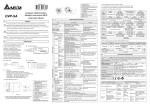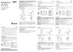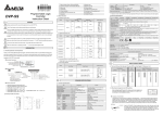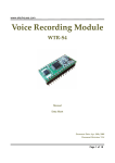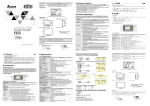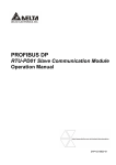
1
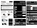
WARNING
This Instruction Sheet only provides descriptions for electrical specifications, general specifications,
installation & wiring, troubleshooting and peripherals. Other detail infromation about programming and
commands is compatible with SA/SC/SX series; please see PLC Application Manual. For more information
about the optional peripherals , please see individual product manual.
This is an OPEN TYPE PLC. The PLC should be kept in an enclosure away from airborne dust, humidity,
electric shock risk and vibration. Also, it is equipped with protective methods such as some special tools or
keys to open the enclosure, so as to avoid the hazard to users and the damage to the PLC.
Never connect the AC main circuit power supply to any of the input/output terminals, as it will damage the
PLC. Check all the wiring prior to power up. To avoid any electromagnetic noise, make sure the PLC is
properly grounded
. Do NOT touch terminals when power on.
2
INTRODUCTION
2.1 Model Name Explanation and Peripherals
Thank you for choosing DELTA’s PLC DVP series.
TheDVP-SX series is a 10-point (4DI+2DO+2AI+2AO)
special main processing unit. Besides the same
commands and functions as DVP-SA/SX/SC series,
2-CH 12-bit analog voltage/current input and 2-CH
12-bit analog voltage/current output are all bipolar.
There is built-in 2-digit 7-segment display corresponds
to internal register directly to display PLC station or
user-defined code.
Model Name
Nameplate Explanation
MODEL :
PLC Model
Input Power Supply Spec.
Output Module Spec.
DVP10SX11R
POWER INPUT
: 24Vdc 6W
OUTPUT MODULE : 2.0A 250Vac 50/60Hz RES. LOAD
Barcode and Serial Number
CPU Version
V1.00
1 0 SX11 R 0 T40 2 0 0 01
DELTA ELECTRONICS INC.
MADE IN XXXXXX
Serial Number
Series Name
Points (6DI+2DO+2AI+2AO)
SX Series
R: Relay
T: Transistor
DC Power Input
Production number
Production week
Production Year 2004
Production factory
Version type
Production model
◎
◎
◎
◎
◎
◎
Items
DVPHPP02: Handheld Programming panel
WPLSoft: Windows Ladder Logic Programming Software
DVPACAB115: 1.5M Cable (HPP
PLC, included in DVPHPP02)
DVPACAB215: 1.5M Cable (PC (DB9+DB25)
PLC)
DVPACAB230: 3.0M Cable (PC (DB9+DB25)
PLC)
DVPACAB2A30: 3.0M Cable (PC (DB9)
PLC)
I
1 Status indicator: POWER, RUN,
ERROR, BAT.LOW
2 RUN/STOP switch
3 2-digital 7-segment display
4 Digital I/O terminal
5 DIN rail clip
6 Analog I/O terminals
Time interrupt
Hi-speed counter
Communication
K Decimal
Units: mm
※ Battery replacement: Please change the battery within 3 minutes,
or the internal data of the PLC (including the program area, RTC
and latched registers) could be lost or destroyed.
8 COM1 (RS-232) (Rx) indicator
9 COM2 (RS-485) (Tx) indicator
10 COM1 (RS-232) Communication
port (Slave)
11 Nameplate
12 Expansion port
C
Counter
S
Step relay
13 Mounting hold of the expansion unit
I001 (X0), I101 (X1), I201 (X2), I301 (X3), I401 (X4), I501
(X5); 6 points (all are rising-edge trigger)
The location pointer of interrupt
subroutine
I6□□ (1ms), I7□□ (1ms), (□□=1~99ms)
I010, I020, I030, I040, I050, I060; 6 points
I150, 1 point
K-32,768 ~ K32,767 (16-bit operation)
D
Register
General
M0~M511
Non-latched (fixed)
100 ms
T0 ~T199
Non-latched (fixed)
Latched
M512~M999
Latched (default)
Start: D1200 (K512)
End: D1201 (K999)
10 ms
T200~T239
Non-latched (fixed)
Clear all M1032
latched area
Factory
Setting
Non-latched
Clear
Unchanged
M1033=Off, clear
M103=On, unchanged
Clear
Unchanged
0
Unchanged
Unchanged
Unchanged
Clear
0
Initial
value
Unchanged
Unchanged
4
0
BUILT-IN ANALOG I/OAND 7-SEGMENT DISPLAY
Built-in 2-CH 12-bit A/D and 2-CH 12-bit D/A are bipolar. It can read A/D converted digital value and get
designated analog output by reading special D or writing into special D. Refer following table for corresponding
special D.
Device No.
D0~D199
Latched
This built-in display corresponds to special D directly.
User can use it to display error code or station when
executing PLC LINK. It is great convenience for system
maintenance. Refer following table for corresponding
special D.
■ Built-in Display
Function
D1056
Present value of AD card
channel 0 (CH0)
D1057
Present value of AD card
channel 1 (CH1)
D1110
Average value of AD card
channel 0 (CH0)
2-digital
7-segment display
Device No.
Function
D1111
Average value of AD card
channel 1 (CH1)
M1196
Number system setting for display (Off:
Decimal, On: Hexadecimal)
D1116
DA card channel 0 (CH0)
M1197
The decimal point setting between the middle
and the right-most numbers
D1117
DA card channel 1 (CH1)
M1198
The decimal point setting after the right-most
number
D1118
Conversion sampling time
(ms)
D1196
Display content
5
ELECTRICAL SPECIFICATIONS
Model
Item
DVP10SX11R/T
DVP08SM11N
DVP08SN11R/T
DVP08SP11R/T
DVP16SP11R/T
MPU: 24VDC (-15%~20%) (with DC input reverse polarity protection),
Expansion Unit: supplied by the MPU
Power supply voltage
Fuse
Power Consumption
Insulation Resistance
2A / 250VAC
5W
-
1W
1.5W
1.5W
> 5 MΩ at 500 VDC (Between all inputs / outputs and earth)
2W
Noise Immunity
ESD: 8KV Air Discharge
EFT: Power Line: 2KV, Digital I/O: 1KV, Analog & Communication I/O: 250V
Damped-Oscillatory Wave: Power Line: 1KV, Digital I/O: 1KV
RS: 26MHz~1GHz, 10V/m
Grounding
The diameter of grounding wire cannot be smaller than the wire diameter of terminals L and N
(All DVP units should be grounded directly to the ground pole).
Environment
Operation: 0℃~55℃ (Temperature), 50~95% (Humidity), Pollution degree 2;
Storage: -25℃~70℃ (Temperature), 5~95% (Humidity); D/A output operation: 0℃~50℃
(Temperature)
Vibration / Shock Resistance
Standard: IEC1131-2, IEC 68-2-6 (TEST Fc) / IEC1131-2 & IEC 68-2-27 (TEST Ea)
Weight (approx.) (g)
158
128
Electrical Specification of Input Point
Input Type
Input Current
Active Level
154 /146
141 /136
162 /154
Electrical Specification of Output Point
DC (SINK or SOURCE)
Output Type
24VDC 5mA
Current
Specification
Voltage
Specification
Off→On, above16VDC
On→Off, below 14.4VDC
Special auxiliary relay
M1000~M1999
Latched
M2000~M4095
Latched (default)
Some are latched and can’t
Start: D1202 (K2000)
be changed
End: D1203 (K4095)
10ms
1 ms
100 ms
T240~T245
T246~T249
T250~T255
Accumulative Latched (fixed)
16-bit count up
32-bit count up/down
C0~C95
C96~C199
C200~C215
C216~C234
Latched (default)
Latched (default)
Non-latched
Non-latched
Start:
D1208
(K96)
Start:
D1210 (K216)
(fixed)
(fixed)
End: D1209 (K199)
End: D1211 (K234)
For general
Latched
Special register
Latched
S0~S9
S10~S19
S20~S511
S512~S895
Factory setting is latched
Start: D1214(K512)
It is fixed to be non-latched
End: D1215(K895)
Non-latched (fixed)
File Register
Clear all M1031
non-latched area
Approvals
COM1: RS-232, COM2: RS-485 (Master/Slave), They can be used at the same time.
MPU built-in bipolar 2-CH A/D, D/A, 12 bits, 2-digital 7-segment display, built-in RTC
Use the same modules (AD, DA, PT, TC, XA, RT) of SS series. (Max. 8 Expansion Unit points)
General
14 DIN rail (35mm)
15 Expansion unit clip
16 COM2 (RS-485) Communication
port
17 DC Power input
I/O refresh command is available
*1: The non-latched area is fixed, and can’t be changed.
*2: The non-latched area can be changed to a latched area with parameter setting.
*3: The latched area can be changed to a non-latched area with parameter setting.
*4: The latched area is fixed, and can’t be changed.
7 I/O point indicators
RUN STOP
Special M, Special D,
Initial value
Index register
K-2,147,483,648 ~ K2,147,483,647 (32-bit operation)
H0000 ~ HFFFF (16-bit operation), H00000000 ~ HFFFFFFFF (32-bit operation)
H Hexadecimal
T
Timer
STOP RUN
Basic commands (several us)
External interrupt
M
Auxiliary
Relay
POWER
Off On
File register
Application Commands
(10~hundreds us)
Program language
Commands + Ladder Logic + SFC
Including the Step commands
Program Capacity
7920 STEPS
SRAM + Battery
Commands
32 Basic sequential commands (including STL/RET)
168 Application commands
X External input relay
X0~X177, octal number system, 128 points
Total Correspond to external input point
256
Y External output relay
Y0~Y177, octal number system, 128 points
Correspond to external output point
points
General
M0~M511, 512 points (*1)
Total
Auxiliary
Contacts can switch to On/Off in
M512~M999, 488 points (*3)
M
Latched
4096
Relay
program
M2000~M4095, 2096 points (*3)
points
Special
M1000~M1999, 1000 points (some are latched)
T0~T199, 200 points (*1)
100ms
T192~T199 for Subroutine
When the timer that set by TMR
Total
T250~T255, 6 points Accumulative (*4)
command reaches the preset
T
Timer
256
value, the T contact with the same
T200~T239, 40 points (*2)
points
10ms
number will be On.
T240~T245, 6 points Accumulative (*4)
1ms
T246~T249, 4 points Accumulative (*4)
C0~C95, 96 points (*1)
16-bit count up
C96~C199, 104 points (*3)
When the counter that set by CNT
32-bit count
C200~C215, 16 points (*1)
Total
(DCNT) command reaches the
C216~C234, 19 points (*3)
C Counter up/down
250
preset value, the C contact with the
points
C235~C245, 1 phase 1 input, 9 points (*3)
same number will be On.
32bit high-speed
C246~C250, 1 phase 2 inputs, 3 points (*3)
count up/down
C251~C254, 2 phase 2 inputs, 3 points (*3)
Initial step point S0~S9, 10 points (*1)
Usage device of step ladder
Zero point reset S10~S19, 10 points (use with IST command) (*1)
Total diagram (SFC)
Step
S
1024 Latched Range:
General
S20~S511, 492 points (*1)
point
points Start: D1214 (K512)
Latched
S512~S895, 384 points (*3)
End: D1215 (K895)
Alarm
S896~S1023, 124 points (*3)
When the timer reaches the preset
T Current value of the timer
T0~T255, 256 points
value, the contact of timer will be
On.
When the counter reaches the
C0~C199, 16-bit counter, 200 points
C Current value of the counter
preset value, the contact of counter
C200~C254, 32-bit counter, 50 points
will be On.
General
D0~D199, 200 points (*1)
D200~D999, 800 points (*3)
Total Can be memory area for storing
Latched
Data
D
5000 data. E and F can be used as the
D2000~D4999, 3000 points (*3)
register
points special purpose of index indication.
Special
D1000~D1999, 1000 points
Index
E0~E3, F0~F3, 8 points (*1)
None File register
0~1599 (1600 points) (*4)
Expansion register for storing data.
For master control nested
Control point of master control
N
N0~N7, 8 points
loop
nested loop
P For CJ, CALL commands
P0~P255, 256 points
The location point of CJ, CALL.
Execution Speed
Programming port
Analog Volume / RTC
Special Expansion Module
2.2 Product Profile and Outline
Remarks
Stored program, cyclic scan system
Batch processing method (when END command is
executed)
I/O Processing Method
Memory Type
Latched
Specifications
Control Method
Constant
Peripherals
FUNCTION SPECIFICATIONS
Interrupt Service
1
※ When switching between power On/Off or MPU RUN/STOP modes:
Battery socket connection
Battery mount
Relay (bit mode)
DVP-SX
Multi-function, Built-in Analog
I/O, Multiple Commands PLC
Instruction Sheet
3
21
22
Register (WORD data)
5011627202-SXE2
http://www.delta.com.tw/industrialautomation/
2 pin removable terminal (standard accessory)
Power input cable (standard accessory)
Battery Cover
18
19
20
Pointer
2006-01-12
32-bit high-speed count up/down
C235~C245
C246~C255
Latched (default)
Start: D1212 (K235)
End: D1213 (K255)
For general
S896~S1023
Special registers
D200~D999
D1000~D1999
Factory setting is latched.
Some are latched and can’t
Start: D1216 (K200)
be changed.
End: D1217 (K999)
K0~K1599, Latched (fixed)
Responding
Time
About 10ms (An
adjustment range of 0~20
ms could be selected
through D1020 and D1021)
6
Maximum
Loading
Responding
Time
Relay-R
Transistor-T
1.5A/1 point
(5A/COM)
0.3A/1 point @ 40℃; When the output of Y0
and Y1 is high-speed pulse, Y0 and Y1 =
30mA
Below 250VAC,
30VDC
30VDC
75VA (Inductive)
90 W (Resistive)
About 10 ms
9W/1 point
Off→On 20us
On→Off 30us
Input
Model
DVP10SX11R
DVP10SX11T
Power
24VDC
+20%
-15%
Point
Output
Type
Point
Type
DI
AI
DI
AI
DO
AO
4
2
2
2
-20~20mA
range(-1000~+1000)
-10~+10V
range(-2000~+2000)
2
4
DC24V/5 mA
Sink or
Source
2
2
Latched
7
Y0 and Y1 are specified
points for high-speed pulse
MODEL NAME & I/O CONFIGURATION
It is fixed to be latched
D2000~D4999
Factory setting is latched.
Start: D1218 (K2000)
End: D1219 (K4999)
When the output of Y0 and
Y1 is high-speed pulse, Y0
and Y1 = 0.9W (Y0 = 32kHz,
Y1 = 10kHz)
INSTALLATION & WIRING
7.1 PLC Mounting Arrangements and Wiring Notes
DO
AO
-20~20mA
(range:-2000~+2000)
-10~+10V
Resistor (range:-2000~+2000)
Relay
Installation of the DIN rail
When installing the DVP series
PLC, make sure that it is
installed in an enclosure with
sufficient space (as shown
below) to its surroundings so as
to allow heat dissipation.
The DVP-PLC can be secured to a cabinet by using the DIN
rail that is 35mm high with a depth of 7.5mm. When
mounting the PLC on the DIN rail, be sure to use the end
bracket to stop any side-to-side motion of the PLC, thus to
reduce the chance of the wires being pulled loose. At the
bottom of the PLC is a small retaining clip. To secure the
PLC to the DIN rail, place it onto the rail and gently push up
the clip. To remove it, pull down the retaining clip and gently
pull the PLC away from the DIN rail. As shown on the right:
Loop Equivalent Circuit of Input Point
Wiring Loop
+5V
22-16AWG
Operation & Test
+24V
S/S
D
OV
S/S
X0
X1
X2
24VDC
X0
Source Type
D > 50 mm
Notes:
1. Please use 22-16AWG (1.5mm) wiring (either single or multiple core) for I/O
wiring terminals. The specification for the terminals is as shown on the left.
PLC terminal screws should be tightened to between 1.95 kg-cm (1.7 in-lbs).
Output Point Wiring
DVP-**-**-11-R
1.
There are two kinds of DVP-SX Series PLC output modules:
Relay and Transistor. For relevant electrical specification,
please refer to the function specification.
2.
Be careful with the connection of the common terminals when
wiring outputs. For example, when wiring DVP12SX11R,
output terminal Y0 uses one common terminal C0, Y1 uses C1,
as shown below:
LOAD
Y0
2. I/O signal wires or power supply should not run through the same multi-wire
cable or conduit. Use Copper Conductor Only, 60/75 °C
<1.5mm
Use HPP to execute the forced On/Off test of the output contact.
SOURCE
SOURCE Mode
Wiring
3.
24VDC
24G
D
DVP
MP
After using the peripheral devices to write the program into the MPU and that the ERROR LED of the MPU
is not on, it means that the program in use is legitimate, and it is now waiting for the user to give the RUN
command.
+24V
DC Type
(DC Signal IN)
D
D
2.
LED
POWER
RY
C0
7.2 Wiring Notes
RELAY OUTPUT
Power Input Wiring
If the “ERROR” LED of the MPU is not blinking, use RUN/STOP switch or the peripheral devices (HPP or
WPLSoft) to give the RUN command, and the RUN indicator will then be on. If the “RUN” LED is not on, it
indicates that there is no program inside the PLC.
HPP could be utilized to monitor the settings and the registered values of the timer (T), the counter (C) and the
data register (D) during operation, and moreover, to force the output contacts to conduct the On/Off action. If
the ERROR LED is on (but not blinking), it means that the setting of the user’s program has exceeded the
preset time-out limit. At this case, please turn the PLC RUN/STOP switch to STOP, and find out the address
of the time-out program by special data register D1008. ”WDT” instruction can be used to solve the problem.
PLC Input/Output Reaction Time
The total reaction time from the input signal to the output operation is calculated as follows:
Reaction Time = input delay time + program scan time + output delay time
DVP-SX series input power supply is DC input. Please take a note of listed items when operating DVP-SX. Series.
Input delay time
1. Please make sure the power is at terminals 24VDC and 0V (power range is 20.4VDC~28.8VDC). When
voltage is lower than 20.4VDC, PLC will stop operating, all outputs will turn Off and ERROR LED will flash
continuously.
DVP-**-**-11-T
Program scan time
Output delay time
LOAD
LED
2. If the power-off time is less than 10ms, the PLC still operates unaffectedly. If the power-off time is too
long or the power voltage drops, the PLC will stop operating and all the outputs will be Off. Once the
power is restored, the PLC will return to operate automatically. (There are latched auxiliary relays and
registers inside of the PLC, please be aware when programming.)
Y0
T
R
G
< 0.3A
C0 Y0 C1 Y1
C0
Action indication: When the output point is active, the
corresponding indicator at the front will be on.
TRANSISTOR OUTPUT
3.
DC Input Type
Voltage input
-10V~+10V
20.4V~28.8V
24V
S/S
0V
X0
X1
CH0
X2
*3
5V
DC/DC
Current input
-20mA~+20mA
Since the PLC is in control of numerous devices, motion of either one device could affect the motion of other
devices, therefore the breakdown of either one device would consequently be detrimental to the whole auto
control system, and danger will thus be resulted. Please use the recommended wiring below for the power
input:
Power supply for AC loads
5
MC
Power Circuit Protection Fuse (3A)
1
Power On pilot indicator
4
Emergency stop
The machinery must provide a quick manual method
8
2
disconnecting all system power.
Guard
Limit
Circuit isolation device (System Power Disconnect)
Utilize the electromagnetic contactor and the relay to be
MC
3
MC
the isolation unit of the power circuit to prevent the
1
possible instability of the system when the power is
supplied on and off.
DVP PLC MPU (main processing unit)
Grounding
7
L
N
Power supply:
6
AC: 100~240VAC, 50/60Hz
DC: 24VDC
V+
I+
COM
Input Point Wiring
The input signal of the input point is the DC power DC input.
SOURCE, defined as follows:
There are two types of DC type wiring: SINK and
250
Source = Current flows out of common terminal S/S
S/S
X0
Sinking
X0
AC drive, recorder,
scale valve...
CH1
V+
I+
COM
power wiring.
CH0
Note 5: If the noise interference from loaded
input wiring terminal is significant,
0.1~0.47μF 25V for noise filtering.
CH1
V+
I+
COM
Note 6: Please connect
terminal and
shielding cable *4
power module
analog output module
terminal to system earth point and
make system earth point be grounded
terminal of
power module
DC24V
24+
24-
DC/DC
converter
or connects to machine cover.
+15V
AG
-15V
Warning: DO NOT wire to the No function
terminal
class 3 grounding
(100 or less)
8
TRIAL RUN
The “POWER” LED at the front of the MPU or the Expansion Units will be lit (in green) if the power is on. If the
indicator is not on when the MPU is powered up, it means that the 24V DC power supply of the PLC is
overloaded. It is thus necessary to remove the wiring on terminals +24V and 24G, and to use a 24VDC power
supply instead. If the ERROR LED is blinking swiftly, it suggests that the +24V power supply of the PLC is
insufficient.
There is also a “BAT.LOW” LED at the front of the MPU. When the LED is on, it indicates that the battery
voltage is insufficient. Please change the batter (within 3 minutes) as soon as possible; otherwise the user
programs and the data in latched area may be lost.
24VD C
24G
SIN K
Preparation
+5V
+24V
OV
S/S
X0
X1
24VDC
Sink Type
X2
1.
The DVPHPP handheld programming panel and the WPLSoft (the Windows version) editing program of
the ladder diagram are both good for use with the DELTA DVP-PLC. Also, the PLC could connect with
the DVP12SX MPU through specific transmission wire to execute the program transmission, the MPU
control and the program monitoring.
9
TROUBLESHOOTING
☼ “POWER” LED
0.1~0.47μF 25V for noise filtering.
please connect a capacitor with
current output
-20mA~20mA
2.
Judge the errors by the indicators on the front panel. When errors occurred on DVP PLC, please check:
☼ Low Battery Voltage Indication
Wiring Loop
+24V
X0
shielding cable *1
The basic commands and the application commands of the MPU of this series are totally applicable to
the DELTA DVP-PLC SA/SX/SC Series MPU. Refer to the DELTA PLC Technique Application Manual
for relevant basic commands and application commands.
please connect a capacitor with
Note 4: Please isolate analog output and other
CH0
1.
input wiring terminal is significant,
The “LOW V.” LED on the Expansion Unit is an indication that the input power voltage is insufficient, thus all
outputs of the expansion unit should be turned off.
Sourcing
S/S
100K
☼ Low Voltage Indication
S/S
Loop Equivalent Circuit of Input Point
Note 3: If the noise interference from loaded
☼ Power Indication
◎ There are two types of DC type wiring: SINK and SOURCE, defined as follows:
Sink = Current flows into the common terminal S/S
CH1
AG
voltage output
-10V~+10V
AC drive, recorder,
scale valve...
out between V+ and I+ terminals.
100K
CH1
*5
power wiring.
100K
Note 2: If input signal is in current, please short
Shielded*1
Safety Wiring
CH0
Note 1: Please isolate analog input and other
AG
*2
SINK Mode
250
Shielded*1
2A
DC Type
(DC Signal IN)
V+
I+
COM
Basic Commands and Application Commands of the PLC:
Isolated circuit: The optical coupler is used to isolate signals
between PLC internal circuits and input modules.
100K
Factory setting: 10 ms. Please refer to the usage of special
register D1020~1021.
Please refer to the usage of special register D1010.
Relay module: 10ms. Transistor module: 20~30us.
Prior to applying power, please verify that the power lines and the input/output wiring are correct. And be
advised not to supply AC110V or AC220V into the I/O terminals, or it might short-circuit the wiring and
would cause direct damage to the PLC.
There is a “POWER” LED at the front of the MPU. When the MPU is powered On, the green LED light will be on.
If the indicator is not on when the MPU is powered up and with the input power being normal, it is an indication
that the PLC is out of order. Please have this machine replaced or have it repaired at a dealer near you.
☼ PLC “RUN” LED
Identify the status of the PLC. When the PLC is in operation, this light will be on, and users could thus use HPP
or the editing program of the ladder diagram to give commands to make the PLC “RUN” or “STOP”.
☼ “ERROR” LED
If incorrect programs are input to the MPU, or that the commands and the components exceed the allowable
range, the indicator will blink. At this moment, the user should check both the error codes saved in the MPU data
register D1004 and the Error Code Table below to correct the programs. The address that the error occurs will
be stored in data register D1137 (the address saved in D1137 is invalid in case of common loop error).
When the ERROR LED is on (not blinking), users should make a judgment from the special relay M1008 of the
MPU. If it is On, it indicates that the execution time of the program loop has exceeded the time-out setting (set by
D1000). Please turn the PLC RUN/STOP switch to STOP, and find out the address of the time-out program by
special data register D1008. ”WDT” instruction can be used to solve the problem. Once program modification is
completed, user can re-download the program of PLC and the ERROR LED will be off. If the ERROR LED is still
keep on, please turn off the power and check if there’s any noise or any conductive invader inside the PLC.
☼ “BAT.LOW” LED
When the battery voltage is low, the “BAT.LOW” LED will be on, and the battery should be replaced as soon as
possible; otherwise the user program and the data in latched area will be lost. (On the unplugged PLC, please
change the battery within 3 minutes to retain the PLC’s internal user programs and data). Choose lithium battery
TDRTL-2150/S. Please refer to the following table for battery life information.
Battery life:
Temperature((°C)
0
25
50
70
Life(Years)
9
8
6
5
Precision of calendar timer:
At 0°C/32°F, less than –117 seconds error per month.
At 25°C/77°F, less than 52 seconds error per month.
At 55°C/131°F, less than –132 seconds error per month.
☼ “Input” LED
The On/Off signals of the input point could be displayed through the “Input” LED, or the status of the input point
could be monitored through the device monitoring function of HPP.
☼ “Output” LED
Output LED indicates if the output signals are On or Off. Please check the following items when the LED On/Off
indication does not correspond to the commands: 1. Output contacts may be melted and stuck together due to a
short circuit or current overload. 2. Check wiring and verify that the screws are tight.