1
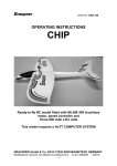
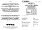
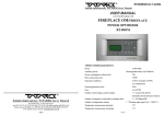
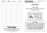
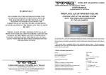
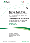
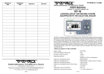
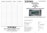
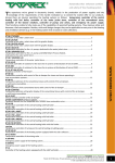
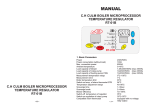
RT12/2009/v.1.0 ANG
Zakład elektroniczny TATAREK Jerzy Tatarek
USER MANUAL
version 1.0 (11.01.2009 program 1v0)
RT-12
TEMPERATURE REGULATOR
OF
THE MIXING VALVE
1.Basic parameters
Power supply
Power consumption without load
Max connection power
Operation conditions
Zakład elektroniczny TATAREK Jerzy Tatarek
50-559 Wroclaw, 75 Swieradowska st.
ph. (071) 367-21-67, 373-14-88, fax 373-14-58; Tax index number 899-020-21-48;
Bank account: BZ WBK S.A. WROCLAW 6910901522-0000-0000-5201-9335
www.tatarek.com.pl.; E-mail: [email protected]
12
Housing protection class
Fuse
Number of outputs to control the valve drive
Number of outputs to contorl the circulating pump
Number of temperature sensors
Temp. measurement precision
Temp. measurement resolution
Input of the room thermostat
Input of the emergency thermostat
1
230V/50Hz
2W
600VA
0÷40 oC, humidity 10÷90%
no condensation
IP41
3,15A/250V
2 * 200VA/230V/50Hz
1 * 200VA/230V/50Hz
1 * KTY210
+/- 2 oC
1 oC
1 * 2mA /5V
1 * 2mA /5V
2. Principle of operation
. The regulator controls the mixing valve, keeping the preset temperature at the output of the valve.
The mixing valve must be equipped with a 230V AC motor drive and the limit switches.
The motor of the drive has two windings. Giving a voltage signal to the first winding closes the
mixing valve, causing the temperature decrease behind the valve, giving a voltage signal to the
second winding opens the mixing valve, causing the temperature increase behind the valve.
The regulator is equipped with a temperature sensor to be mounted on the tube behind the mixing
valve and 2 outputs to control the valve drive. Additionally the regulator has got the output to control
the circulating pump.
It is possible to have a cooperation between the regulator and a room thermostat. After reaching the
preset temperature on the thernmostat in a given room, the regulator automatically decreases the
temperature behind the valve. The value of that decrease must be set while mounting the regulator.
The default value is 15 oC.
The regulator protects the heat receivers connected behind the valve against high temperature. If the
temperature increases over the preset threshold the valve is closed, the circulating pump is turned off
and the emergency signal switches on.
The regulator allows an additional emergency thermostat to be connected. If the system receiving
heat , connected behind the valve, is sensitive to too high temperature (e.g. some types of floor
heating systems) you can connect to the regulator an additional emergency thermostat. The switching
on of the thermostat causes closing the mixing valve, turning off the circulating pump and emergency
signal.
By pressing one button you can easily turn off the regulator (e.g. in summer time).
The circulating pump will be then switched off and the mixing valve closed off.
Admission
date
Realization
date
Signature
Room
thermostat
Regulator
RT12
Power supply
230V AC
Valve
drive
Emergency
thermostat
M
BOILER
Mixing
valve
Circulating
pump
Temperature
sensor
Heat
receivers
or
floor
heating
Fig.1 Operation layout of the regulator
2
11
Remarks
2.1Operation of the regulator
CE CONFORMITY DECLARATION
Ref. No. 58.RT.01.2007/1/B
We,
ZAKŁAD ELEKTRONICZNY TATAREK Jerzy Tatarek
75 Swieradowska St. , 50-559 Wroclaw
declare under our sole responsibility that
the product: TEMPERATURE REGULATOR OF THE MIXING VALVE
2.2 Cooperation with the room thermostat
model: RT-12
is in conformity with the basic requirements included in Directive EMC 2004/108/WE of 15.12.2004 (the
electromagnetic compatibility law of 13.04.07) and Directive LVD 2006/95/WE of 21.08.07 (Laws Journal
of 2007 No. 155 pos. 1098) regarding the requirements for electric devices.
To the conformity evaluation the following harmonized standards were used:
PN-EN 60730-2-1: 2002 PN-EN 60730-1: 2002 -
When the power supply is given to the regulator or it'll be switched on by the keyboard, the
circulation pump is being turned on. At first the regulator shuts the mixing valve. The procedure of
shutting lasts for 120s. Then the essential procedure of controling occurs. The algorithm compares
the preset temperature (set by a user) with the measured temperature. If the measured temperature is
too low, the regulator with a specific impulse opens a little the valve. If the measured temperature is
too high, the regulator closes a little the valve. Checking the temperature and the correction of setting
the valve the regulator carries out cyclically in its whole operation time. The size of the closing and
opening impulses and the interval between them is set based on the difference between the preset
and measured temperature and also on the speed of the measured temperature's changes.
Automatic electric regulators for house usage and the like. Part 2-1:
Specific requirements regarding electric regulators for electric house
devices
Automatic electric regulators for house usage and the like.
Part 1: General requirements.
PN-EN 55022: 2000 Electromagnetic compatibility (EMC)- IT devices
Characteristics of radioelectric noises. Acceptable levels and measurement methods
Complementary information:
The regulator can cooperate with a room thermostat. On the contacts of the regulator where a
thermostat can be connected by default the jumper is mounted. After removing the jumper and
connecting a thermostat the algorithm will be changed. If the room temperature is too low (contact of
the thermostat is shorted), the regulator operates normally, keeping the preset temperature. But if the
temperature is too high (contact of the thermostat is open) the regulator starts keeping temperature
lower than the preset one. The size of that decrease ought to be set by an installer. The default is 15 oC.
2.3 Cooperation with the emergency thermostat
In order to protect some of the heat receivers against high temperature, the system with the RT12
regulator can be equipped with an additional emergency thermostat. By default on the contacts of the
regulator where an emergency thermostat can be connected the jumper is mounted to allow normal
operation without the thermostat.After removing the jumper and connecting the thermostat, the
regulator reacts with an emergency signal, closing the mixing valve and turning off the circulating
pump if the temperature of the thermostat is exceeded (its contact will be shorted).
Laboratory IASE 51-618 Wroclaw, 1 Wystawowa st.
Test report No.
39/DL/I/07 of 22.06.2007
41/DL/I/07 of 03.07.2007
3 Handling the regulator
Electronic Engineering Plant TATAREK
has initiated management system and complies with the following standard :
ISO9001: 2000 CERTIFICATE No. 133/2004 of 01.2004
Polish Foreign Trade Chamber
Emergency
takes place
Regulator is
turned on.
The last two digits of the year in which the CE marking was affixed: 07
Place of issue:
Manufacturer representative:
Wroclaw
Mirosław Zasępa
Date of issue:
Position:
08.2007
Konstruktor
Measured
temperature
Parameter
setting mode
Fig.2 Conrol panel
10
3
Signalling:
Normal operation,
operation with
the decreased
temperature
WARRANTY
3.1 Turning on/ off the regulator
.
Display and the LEDs
are off when the regulator
is switched off.
The LED lights all the
time, independent of the
regulator's switch-off
1.Warranty is valid [24] months from the date of sale.
2.Producer does not take responsibility for any mechanical damages made by user.
3.MAKING REPAIRS OR MODYFYING THE DEVICE BY USER IS
FORBIDDEN AND CAUSES WARRANTY CANCELATION
4.Warranty card is valid only with date of sale, seller's signature and stamp
5.Warranty and after-warranty repairs should be done only by producer, damaged
regulators should be sent to producer in order to make all repairs needed.
6.Warranty protection involves the EU
7.Warranty does not exclude, not restrict and not suspend buyer’s rights coming from
the incompatibility of the article with the agreement (Laws Journal No. 141 Pos. 1176)
WARNING !
Long pressing (6s) of the
button causes the switch-on
or switch-off of the regulator
! DESPITE THE SWITCH-OFF OF THE REGULATOR, IT'S UNDER DANGEROUS
ANY MODIFICATION OF THE REGULATOR MADE BY USER CAN BE
THE CAUSE OF SAFETY CONDITIONS DETERIORATION AND CAN
EXPOSE THE USER TO ELECTRIC SHOCK OR DAMAGE DEVICES
SUPPLIED.
VOLTAGE. THE OUTPUTS (CONTROLLING THE CIRCULATING PUMP AND MIXING
VALVE) ARE ALSO UNDER DANGEROUS VOLTAGE.
When the RT-12 regulator is switched off, the display and the LEDs go out.Only the LED
signalling power supply existence lights. The circulating pump is turned off.
The output of closing the mixing valve is turned on.
3.2 Change of the preset temperature
Pressing the buttons up/
down starts presetting the
temperature.You can
increase or decrease it
with the buttons
Connection cable of regulator may be replaced only
by producer or his authorized service locations
WARNING!
1. Producer does not take the responsibility for damage
caused by atmospheric discharge
2. and overvoltage in the mains
3. Burnt fuses are not subject to warranty replacement
Date of sale
Seller's signature and stamp
ARGO-FILM
Recycling Plant No. 6
180 Krakowska st., 52-015 Wroclaw
Worn out electronic
and electric devices must be transfered to ph.: 071 794 43 01,
0 515 122 142
the utilization collection place, where will
be accepted for free
Register No.. GIOS: E 0002240WZ
While setting, on the
display the preset
temperature blinks
.
.
If the LED lights the
temperature
setting mode is active.
At the end press this
button to confirm.
Zakład elektroniczny TATAREK Jerzy Tatarek
50-559 Wroclaw, 75 Swieradowska st
ph. (071) 367-21-67, 373-14-88, fax 373-14-58; tax index number 899-020-21-48;
Bank account : BZ WBK S.A. O/WROCŁAW 6910901522-0000-0000-5201-9335
www.tatarek.com.pl.; E-mail: [email protected]
4
9
Description of the RT-12 contacts:
No Name
1
N
2
L
3
N
4
L
5
N
6
L-Z
7
L-O
8
PE
9
PE
10
PE
11
Tx
12
Tx
13
Tp
14
Tp
15
Ta
16
17
18
Ta
-
Description
Power supply 230V 50Hz -neutral cable
Power supply 230V 50Hz – phase cable
Circulating pump 230V 50Hz – neutral cable
Circulating pump 230V 50Hz – phase cable
Drive of the mixing valve 230V 50Hz – neutral cable
Drive of the mixing valve 230V 50Hz – phase cable, direction of shutting the valve
Drive of the mixing valve 230V 50Hz – phase cabley, direction of opening the valve
Power supply 230V 50Hz - protective cable
Pompa obiegowa 230V 50Hz – protective cable
Drive of the mixing valve 230V 50Hz – protective cable
Temperature sensor
Temperature sensor
Thermostat with the NC contact
Room thermostat
NC-normally closed. If the room
temperature is too low the
contact should be closed. After
exceeding the preset temperature
the contact should open.
Room thermostat
Thermostat with the NC contact.
e.g. type bimetallic. If the
temperature exceeds the limit level
the contact should open.
Emergency thermostat
Emergency thermostat
After setting the preset temperature its value must be confirmed with the confirmation button. If
you don't do that after 10s the regulator restores the previous value and gets back to show the
measured temperature.
4. Chapters for an installer
4.1. Change of the parameters
The RT-12 regulator after installing requires to have a few parameters set.
The list of parameters:
Symbol of
Parameter
P0
P1
P2
do not connect !
do not connect !
P3
P4
Attention ! Remember ! If you don't want to connect a thermostat you must in its place jumper
(short) the connections. As well when you want to connect a thermostat first you need to remove
the jumper.
Description
Lowering the temperature for the operation with a room thermostat.
If the room temperature is high and the thermostat turns on, then
the regulator will keep the lower temperature on the heat receivers.
This parameter defines by what degrees this temperature must be lower.
Dynamics of the heating system.This parameter defines
the reaction speed of the regulator at temperature changes.
If you consider the temperature on the heat receivers too slowly
goes to the preset temperature, you need to delicately increase this
parameter. Too much dynamics may cause overcontrolling.
znacznych przesterowań.
Emergency temperature. If the measured sensor
temperature reaches the emergency value, the regulator
turns on an emergency signal, closes the mixing valve
and turns off the circulating pump. The emergency state
lasts till the temperature lowers to 10 oC from that value.
Limit temperature. Up to that value a user can preset the
temperature
Insensibility zone. If the measured temperature is close to the
preset temperature and finds within the insensibility zone,
the regulator doesn't change the settings of the mixing valve
Minimum Maximum
value
value
0 oC
40 oC
15
1
99
80 oC
50 oC
99 oC
50 oC
30 oC
90 oC
10 oC
0.0 oC
99 oC
The change of the parameters you begin from a simultaneous pressing of the buttons up/down
and holding them down for 6s.
Simultaneous pressing of the
buttons up/down and holding
them down for 6s begins
the parameter change mode.
With the buttons you select
also the parameters
to change.
In the parameter change
mode the display shows
up the symbol of
the parameter to change.
8
Default
value
15 oC
Blinking LED means
the parameter change
mode is active.
5
When you selected
a parameter you want
to change, press the
confirmation button
and start its change.
If for 10s you don't press any button, the regulator gets back to the normal operation. The
parameter setting mode ends. After selecting a parameter to change and pressing the confirmation
button you begin changing the parameter value.
1
2
3
4
5
6
7
8 9 10
11
12
13
14
15
16
17
18
Buttons up/down
you change the selected
parameter value
POWER SUPPLY
230V AC
PE PE PE
8
N
L
3
L
Current value of the
selected parameter
Blinking LED means
the parameter change
mode
After setting the new
value, press the
confirmation button
4
N
5
L-Z
SERVO OF
THE VALVE
10
2
N
PUMP
9
1
6
L-O
7
If for 10s you don't press any button the previous value is restored and the regulator comes back
to the parameter selection mode
Fig. 3 Layout of connecting power supply, pump and valve drive.
4.2 Installing the regulator
! THE REGULATOR IS SUPPLIED BY 230V/50HZ .
ANY MOVES REGARDING INSTALLATION SHOULD BE MADE AT
THE DISCONNECTED MAINS.
1
2
3
4
5
6
7
8 9 10
11
12
13
14
15
16
17
18
! THE REGULATOR HAS TO BE CONNECTED TO THE MAINS WITH THE
ZERO-PIN THROUGH A DIFFERENTIAL DEVICE ACC. TO THE VALID LAWS
! THE PRODUCER DOESN'T TAKE ANY RESPONSIBILITY FOR
DAMAGES CAUSED BY WRONG USAGE OF THE REGULATOR.
Connection layout of the elements of the regulator is presented on fig. 3 and 4
6
11
12
13
14
15
16
17
18
Temperature sensor - Tx
Jumper or room thermostat - Tp
Jumper or emergency thermostat - Ta
Fig. 4. Layout of connecting temperature sensor and thermostats.
7