1
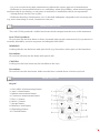
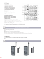
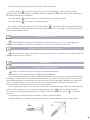
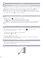
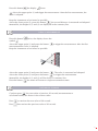
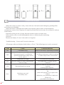
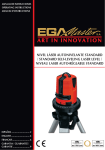
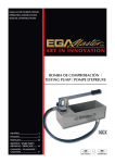
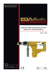
OPERATING INSTRUCTIONS
LASER DISTANCE DETECTOR
COD. 51269
GUARANTEE......................... 13
PRODUCT INTRODUCTION
Code 51269, Handheld Laser Distance Meter, is specially designed for users. It is a meter with
high-precision and multi-function distance measurement. Code 51269 can measure distance,
area and volume, Pythagorean Laws can also be used in code 51269 to measure indiectly. Code
51269 which is light, easy to use and reliable to measure,can make sure your measurement more
accuracy, easier and faster.
Code 51269 can widely apply to Construction, Upholster, Property, Traffic, Fire-Fighting,
Gardens, Urban Planning, Water Mornitoring, Electric Power Overhaul,etc. As the replacer of
traditional measuring instrument (for example,measuring tape), code 51269 is your best choice.
UNPACKING INSPECTION
Unpack and check, if there is any damage or loss.
1. Mainframe one unit
2. User manual one copy
3. AAA battery(2×1.5V) one piece
4. Carrying case one unit
5. Mini screwdriver one piece
SAFETY INSTRUCTION
PERMITTED USE
- Measuring distances
- Computing functions, e. g. areas and volumes
- Indirect Measuring with Pythagorean Prohibited use
- Using the instrument without instruction
- Using outside the stated limits
- Deactivation of safety systems and removal of explanatory and hazard labels
- Opening of the equipment by using tools (screwdrivers, etc.), as far as not specifically permitted
for certain cases
- Carrying out modification or conversion of the product
2
- Use of accessories from other manufacturers without the express approval of manufacturer.
- Deliberate or irresponsible behavior on scaffolding, when using ladders, when measuring near
machines which are running, or near parts of machines or installations which are unprotected
- Aiming directly into the sun or glare
- Deliberate dazzling of third parties; also in the dark Inadequate safeguards at the surveying site
(e.g. when measuring on roads, construction sites,etc.)
LASER CLASSIFICATION
The code 51269 produced a visible laser beam which emerges from the front of the instrument.
Laser Class II products:
Do not stare into the laser beam or direct it towards other people unnecessarily. Eye protection is
normally afforded by aversion responses including the blink reflex.
WARNING
Looking directly into the beam with optical aids (e.g. binoculars, telescopes) can be hazardous.
Precautions:
Do not look directly into the beam with optical aids.
CAUTION
Looking into the laser beam may be hazardous to the eyes.
Precautions:
Do not look into the laser beam. Make sure the laser is aimed above or below eye level.
METER STRUCTURE
Keypad
1. ON / MEAS (On/measuring) button
2. Area / volume button
3. Indirect measurement button
4. Continuous measurement button
5. Plus (+) button
6. Minus (-) button
7. Storage button
8. Reference level button
9. Illuminating button
10. Clear/off button
3
LCD Display
1 Laser active
2 Reference level (front)
3 Reference level (rear)
4 Reference level (End piece)
5 Continuous measurement
6 Instrument error warning
7,8,9,10,11
Variable measuring functions
Length measurement
Area measurement
Volume measurement
Indirect (2 times) measurement
Indirect (3 times ) measurement
12 Battery status
13 Historical memory, call up values
14 First value display line, minimum value
15 Second value display line, maximum value
16 Third value display line
17. Summary line for last measure or calculation result
SETTING AND OPERATION OF METER
Switching on and off
Switches on the instrument and laser.
Press this button longer to switch off the instrument..
The instrument switches off automatically after three minutes of inactivity.
CLEAR button
The last action is cancelled or the data display is cleared.
REFERENCE LEVEL SETTING
4
The default reference setting is from the rear of the instrument.
Press this button
to take the selection from the front edge . A special beep sounds
whenever the reference setting is changed. After a re-startup the reference returns automatically to
the default setting (rear reference).
Press this button
again to take the next selection from end piece edge.
Press this button
, to set the rear reference again.
In a word, to select the reference level, push button
repeatedly until the required reference
level is indicated in the display. Each time after switching on, the rear edge of the measuring tool is
preset as the reference level.
DISPLAY ILLUMINATION
Click illumination button of the display can be switched on or off, User can trigger the
function when he/she is in darkness situation. The value is clear viable on the LCD.
DISTANCE UNIT SETTING FOR INSTRUMENT
Click the button longer change the next type of unit, m, ft. in, ft/in then to continue click the
button for the next unit selection.
MEASURING
SINGLE DISTANCE MEASUREMENT
Press to activate the laser. Press again to trigger the distance
measurement. The measured value is displayed immediately.
Continuous Measurement & Max and Min Measurement The continuous measurement function
(tracking) is used for the transferring of measurements, e.g., from construction plans. In continuous
measurement mode, the measuring tool can be moved close to the target, whereby the measured
value is updated approx. every 0.5 seconds. The corresponding dynamically maximum and
minimum values are displayed in the first and second line.
As an example, the user can move from a wall to the required distance, while the actual distance
can be read continuously. For continuous measurement, press
button until the indicator
for continuous measurement appears in the display. And press it again or press
to stop the
function.
The function is terminated after 5 minutes’ continuous measurement.
With this function, customers can measure the max and min distance from a certain point.
5
FUNCTIONS
ADDITION / SUBTRACTION DISTANCE MEASURING.
The next measurement is added to the previous one, then press the button
, the second
measured value is shown and the result is shown automatically.
The next measurement is
subtracted from the previous one. Then press the button
, the result is shown in the summary
line with the previous value in the second line. Operate the above steps repeatedly, the meter will
add or reduce cumulatively.
The last step is cancelled.
AREA
Press once. The
symbol appears in the display.
Press
button to take the first length measurement (e.g. length).
Press
again to take the second length measurement (e.g. width).
After taking the second measurement, the area/surface is automatically calculated and displayed
in the summary line. The last individual measured value is indicated at the second line in the
display.
VOLUME
For volume measurements, push button
measurement appears in the display.
twice until the
indicator for volume
Afterwards, Press this button
to measure the length.
Press this button
for width.
Press button
to take the height,
After taking the third measurement, the volume is automatically calculated and displayed. The
last individual measured value is not displayed.
INDIRECT MEASUREMENT
when measuring heights that require the measurement of two or three
measurements ,as following step:
USING 2 MEASUREMENTS
6
Press this button
, the display
shows.
Aim at the upper point (1) and trigger the measurement. After the first measurement, the
value is adopted.
Keep the instrument as horizontal as possible.
Aim at the lower point (2), press this button
, the second distance is measured and adopted.
Meanwhile, the height of (1) and (2) are displayed in the summary line.
USING 3 MEASUREMENTS
Press this button
twice; the display shows the
symbol .
Aim at the upper point (1) and press the button
measurement the value is adopted.
Keep the instrument as horizontal as possible.
to trigger the measurement. After the first
Aim at the upper point (2) and press the button
. The value is measured and adopted.
Aim at the lower point (3) and press the button
to trigger the measurement.
Meanwhile, the height of (1) and (3) will be shown in summary line.
Press the button
,the meter will return to single measurement status.
HISTORICAL STORAGE
Continue press
the next value of previous 20 records (measurements or
calculated results) are shown in the reverse order.
Press
to retrieve the next value of 20 records .
Press
then retrieve the previous value of 20 records.
7
TECHNICAL SPECIFICATIONS
GENERAL CHARACTERISTICS
Measurement Distance
Measurement Speed
Battery Type
Battery Life
Battery indicator
Dimension
Weight
Laser Type
Laser Dust Protect/Splash Auto power off Auto laser switch-off
0.1m ~ 60m (4 in ~197 ft)
3 times / s
AAA 2 x 1.5V
up to 3,000 measurements
Three states: full, medium, low
116 x 49 x 28 mm
100g (Including batteries)
635nm﹤1mW
Class Class II
proof IP54
after 3 min
after 0.5 min
ENVIRONMENTAL REQUIREMENTS
Altitude: Operating Temperature Storage Temperature 2000m
0°C to +40°C(+32°F to +104°F)
-10 °C to +60°C (14°F to +140°F)
FOLLOWING STANDARDS
EN61326-1 EN60825-1 EMC;
Laser Safety
SPECIFICATIONS
Laser distance meter
Basic functions
Measuring distances
Code 51269
Range
Accuracy
0.1m~60m*
± 1.5 mm**
4 in ~197 ft
± 0.06 in
Measuring units: m / in / ft
Special functions
8
Explanation
Area, Volume Calculations
√
m2 / ft2 / m3 / ft3
Indirect Measuring with
Pythagorean
√
Two or three measurements
Addition/Subtraction
√
Continuous Measurement
√
Max/Min
√
multi-line display
√
Up to four lines show
Reference level setting
√
Front edge or end piece edge
Buzzer indication
√
Backlight
√
white
Auto Bias Technology™
√
Support for external
calibration
error indication
√
Display error code
Hold
√
Automatic
History measurement recodes
√
20 records
Clear
√
Keyboard Type
Super Soft-Touch (Long life) Over 1 Million Times
* during daylight or if the target has poor reflection properties!
** in favorable conditions (good target surface properties, room temperature)
up to 60 m. In unfavorable conditions, such as intense sunshine, poorly reflecting target surface
(black surface) or high temperature variations, the deviation over distances above 10m may
increase more.
MAINTENANCE
Warning: during replacing battery or measuring, keep the sensitive mirror from scratch or
dirt to avoid damaging the mirror or influencing the measuring precision; and do not charge the
replaced battery to avoid explosion and safety accident!
BATTERY INSTALLATION AND REPLACEMENT
- When the symbol flashes permanently in the display replace the battery immediately.
Use alkaline batteries only.
Remove the batteries before any long period of non-use to avoid the danger of corrosion.
As following steps:
- Turn of the screw, remove battery compartment lid.
- Insert batteries in the two space respectively, observing correct
polarity.
- Close the battery compartment again, and fix the screw for reliability.
9
GENERAL MAINTENANCE
When the surface of meter is dirty, clean with wet cloth and neutral detergent, grinding miller
and solvent are forbidden.
When the meter is damaged and needs to be repaired, please send it to the designated
maintenance center of our company for repair by professional service man, do not repair it without
authorization.
Especially in the process of using, keep the sensitive mirror of meter away
from scratch or dirt to avoid damaging the mirror or influencing the measuring
precision.
Remove the battery if it won’t be used for a long time.
Troubleshooting – Causes and Corrective Measures
All message codes are displayed with either or “Error”. The following errors can be corrected:
Code
Cause
Corrective Measure
204
Calculation error
Refer to user menu, repeat the procedures
208
Cool down instrument, make it working
in stable temperature environment
253
Temperature too high
Cool down the instrument
255
Receiver signal too weak, measurement
time too long
Use target plate or change a good
refection
Received signal too strong
Target too reflective use target plate or do
not aim
at strong light objective
Hardware error and
uncertainty error
Switch on/off the device several times. If
the
symbol still appears, try to replace the
battery,
Otherwise your instrument is defective.
Please call
your dealer for assistance
256
Error
10
Temperature too high
The measuring tool is outside the
operating temperature range from 0
°C to +40 °C
NOTES
IMPORTANT!
The maker will not take responsibility for damage or malfunction as a result of the device being
incorrectly used or, applied for a purpose for whith it was not intended.
According to Waste Electrical and Electronic Equipment directive (WEEE), these ones must
be collected and arranged separately. If you have to throw them out, please, do not use the usual
rubbish. Please, contact your distributor for free recycling.
GUARANTEE
The maker guarantees to the device owner 12 months against any manufacture defect.
This guarantee do not cover the parts wich are consumables.
Note: to apply the guarantee its necesary to send the “GUARANTEE CERTIFICATE” duly filled
within one week after purchased the machine to the maker.
11
CERTIFICADO DE GARANTIA
GUARANTEE CERTIFICATE
CERTIFICAT DE GARANTIE
ARTICULO / ITEM / ARTICLE:.....................................................................................................................
Nº DE SERIE / SERIE Nº / Nº SERIE:............................................................................................................
DISTRIBUIDOR / DISTRIBUTOR / DISTRIBUTEUR:....................................................................................
PAIS / COUNTRY / PAYS:..............................................................................TEL.:....................................
FECHA DE VENTA / SALE DATE / DATE VENTE:.........................................................................................
NOMBRE DEL COMPRADOR / BUYER NAME / NOM DE L’ACHETEUR:...................................................
TEL. COMPRADOR / BUYER TEL. / TEL. DE L’ACHETEUR:.........................................................................
EGA MASTER GARANTIZA AL COMPRADOR DE ESTA MAQUINA LA GARANTIA TOTAL (DURANTE 12 MESES), DE LAS PIEZAS CON DEFECTOS DE FABRICACION. ESTA
GARANTIA NO CUBRE AQUELLAS PIEZAS QUE POR SU USO NORMAL TIENEN UN DESGASTE. PARA OBTENER LA VALIDEZ DE LA GARANTIA , ES ABSOLUTAMENTE
IMPRESCINDIBLE QUE COMPLETE Y REMITA ESTE DOCUMENTO A EGA MASTER , DENTRO DE LOS SIETE DIAS A PARTIR DE LA FECHA DE COMPRA.
EGA MASTER GUARANTEES TO THE BUYER OF THIS MACHINE THE TOTAL WARRANTY (DURING 12 MONTHS), OF THE PIECES WITH MANUFACTURING FAULTS.
THIS GUARANTEE DOES NOT COVER THOSE PIECES WORN OUT DUE TO A NORMAL USE. IN ORDER TO OBTAIN THE VALIDITY OF THIS WARRANTY , IT IS
ABSOLUTELY NECESSARY TO FULFILL THIS DOCUMENT AND RESEND IT TO EGA MASTER WITHIN 7 DAYS FROM SALE DATE.
EGA MASTER GARANTIE A L’ACHETEUR DE CETTE MACHINE LA GARANTIE TOTALE (PENDANT 12 MOIS) DES PIECES AVEC DEFAUTS DE FABRICATION. CETTE GARANTIE
NE COUVRE PAS LES PIECES QUE PAR UN USAGE NORMAL, SOIENT DETERIOREES. POUR OBTENIR LA VALIDITE DE LA GARANTIE, IL EST ABSOLUMENT IMPERATIF
COMPLETER ET ENVOYER CE DOCUMENT EGA MASTER, DANS UN DELAI DE 7 JOURS A PARTIR DE LA DATE D’ACHAT.
SELLO / STAMP / CACHET
EJEMPLAR PARA EGA MASTER / COPY FOR EGA MASTER / EXEMPLAIRE POUR EGA MASTER
CERTIFICADO DE GARANTIA
GUARANTEE CERTIFICATE
CERTIFICAT DE GARANTIE
ARTICULO / ITEM / ARTICLE:.....................................................................................................................
Nº DE SERIE / SERIE Nº / Nº SERIE:............................................................................................................
DISTRIBUIDOR / DISTRIBUTOR / DISTRIBUTEUR:....................................................................................
PAIS / COUNTRY / PAYS:..............................................................................TEL.:....................................
FECHA DE VENTA / SALE DATE / DATE VENTE:.........................................................................................
NOMBRE DEL COMPRADOR / BUYER NAME / NOM DE L’ACHETEUR:...................................................
TEL. COMPRADOR / BUYER TEL. / TEL. DE L’ACHETEUR:.........................................................................
EGA MASTER GARANTIZA AL COMPRADOR DE ESTA MAQUINA LA GARANTIA TOTAL (DURANTE 12 MESES), DE LAS PIEZAS CON DEFECTOS DE FABRICACION. ESTA
GARANTIA NO CUBRE AQUELLAS PIEZAS QUE POR SU USO NORMAL TIENEN UN DESGASTE. PARA OBTENER LA VALIDEZ DE LA GARANTIA , ES ABSOLUTAMENTE
IMPRESCINDIBLE QUE COMPLETE Y REMITA ESTE DOCUMENTO A EGA MASTER , DENTRO DE LOS SIETE DIAS A PARTIR DE LA FECHA DE COMPRA.
EGA MASTER GUARANTEES TO THE BUYER OF THIS MACHINE THE TOTAL WARRANTY (DURING 12 MONTHS), OF THE PIECES WITH MANUFACTURING FAULTS.
THIS GUARANTEE DOES NOT COVER THOSE PIECES WORN OUT DUE TO A NORMAL USE. IN ORDER TO OBTAIN THE VALIDITY OF THIS WARRANTY , IT IS
ABSOLUTELY NECESSARY TO FULFILL THIS DOCUMENT AND RESEND IT TO EGA MASTER WITHIN 7 DAYS FROM SALE DATE.
EGA MASTER GARANTIE A L’ACHETEUR DE CETTE MACHINE LA GARANTIE TOTALE (PENDANT 12 MOIS) DES PIECES AVEC DEFAUTS DE FABRICATION. CETTE GARANTIE
NE COUVRE PAS LES PIECES QUE PAR UN USAGE NORMAL, SOIENT DETERIOREES. POUR OBTENIR LA VALIDITE DE LA GARANTIE, IL EST ABSOLUMENT IMPERATIF
COMPLETER ET ENVOYER CE DOCUMENT EGA MASTER, DANS UN DELAI DE 7 JOURS A PARTIR DE LA DATE D’ACHAT.
SELLO / STAMP / CACHET
EJEMPLAR PARA EL CLIENTE / COPY FOR THE CUSTOMER / EXEMPLAIRE POUR LE CLIENT
C/ ZORROLLETA 11, POL. IND. JUNDIZ
01015 VITORIA, SPAIN P.O.B. APTDO. 5005
TEL. 34 - 945 290 001
FAX. 34 - 945 290 141
[email protected]
www.egamaster.com