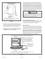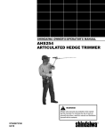
1
INSTALLATION INSTRUCTIONS
CG90CB, CG90UB, CG90TB, CG92TB & CG95TB
High Efficiency 90+ Condensing Gas Furnace
Save these instructions for future reference
WARNING
Improper installation, adjustment, alteration, service, or maintenance can cause injury or property damage.
Refer to this manual. For assistance or additional information, consult a qualified installer, service
agency, or the gas supplier.
WARNING
TABLE OF CONTENTS
Do not store combustible materials, including gasoline and
other flammable vapors and liquids, near the furnace, vent
pipe, or warm air ducts. The homeowner should be
cautioned that the furnace area must not be used as a
broom closet or for any other storage purposes. Such uses
may result in actions that could cause property damage,
personal injury, or death.
SAFETY ................................................. 2
INSTALLATION ...................................... 3
START-UP ............................................ 26
OPERATION ........................................ 27
MAINTENANCE ................................... 30
WARNING
REPAIR PARTS ................................... 31
This furnace is not approved for installation in a mobile
home. Do not install this furnace in a mobile home.
Installation in a mobile home could result in actions that
could cause property damage, personal injury, or death.
CONTROL SYSTEM DIAGNOSTICS .. 32
WIRING DIAGRAMS............................ 33
Manufactured By
Allied Air Enterprises Inc.
A Lennox International Inc. Company
215 Metropolitan Drive
West Columbia, SC 29170
*506185-01*
WARNING
The installation of the furnace, wiring, warm air ducts, venting, etc. must conform to the requirements of the National Fire
Protection Association; the National Fuel Gas Code, ANSI Z223.1/NFPA No. 54 (latest edition) and the National Electrical
Code, ANSI/NFPA No. 70 (latest edition) in the United States; CSA B149.1 (latest edition) Natural Gas and Propane Installation
Codes and the Canadian Electrical Code Part 1, CSA 22.1 (latest edition) in Canada; and any state or provincial laws, local
ordinances (including plumbing or wastewater codes), or local gas utility requirements. Local authorities having jurisdiction
should be consulted before installation is made. Such applicable regulations or requirements take precedence over the general
instructions in this manual.
506185-01
Issue 0938
Page 1 of 36
IMPORTANT SAFETY INFORMATION
The following is a list of safety rules and precautions that
must be followed when installing this furnace.
1. Use only with the type of gas approved for this furnace.
Refer to the furnace rating plate.
2. Install this furnace only in a location and position as
specified in the Location section on page 3 of these
instructions.
3. Provide adequate combustion and ventilation air to the
furnace space as specified in the Combustion and
Ventilation Air section on page 4 of these instructions.
4. Adequate clearance must be provided around the ventair intake terminals as specified in the Venting section
beginning on page 5 of these instructions.
5. Combustion products must be discharged outdoors.
Connect this furnace to an approved vent system only,
as specified in the Venting section beginning on page 5
of these instructions.
6. Never test for gas leaks with an open flame. Use a
commercially available soap solution made specifically
for the detection of leaks to check all connections, as
specified in Gas Supply and Piping beginning on
page 22 of these instructions.
Page 2 of 36
7. Always install furnace to operate within the furnace’s
intended temperature-rise range with a duct system
which has an external static pressure within the
allowable range, as specified in Temperature Rise
on page 28 of these instructions. See furnace rating
plate.
8. When a furnace is installed so that the supply ducts
carry air circulated by the furnace to areas outside
the space containing the furnace, the return air shall
also be handled by duct(s) sealed to the furnace
casing and terminating outside the space containing
the furnace. See Circulating Air Supply on page 22
of these instructions.
9. A gas-fired furnace for installation in a residential
garage must be installed as specified in the Location
section on page 3 of these instructions.
10. The furnace is permitted to be used for temporary
heating of buildings or structures under construction as
specified in the Location section beginning on page 3
of these instructions.
In the State of Massachusetts:
This product must be installed by a licensed Plumber
or Gas Fitter. When flexible connectors are used, the
maximum length shall not exceed 36". When levertype gas shutoffs are used, they shall be T-handle
type.
Issue 0938
506185-01
INSTALLATION
These instructions must be placed on or near the furnace in
a conspicuous place.
The furnace design is certified by CSA International as a
Category IV furnace in compliance with the latest edition of
American National Standard Z21.47/CSA Standard 2.3 for
Gas-Fired Central Furnaces, for operation with natural gas
or propane. Consult the rating plate on the furnace for gas
type before installing.
Location
To provide proper operation and satisfactory performance, care
must be taken in choosing the location for this furnace. The
atmosphere in which the furnace operates must be free of
contaminants such as chlorides and sulfates.
The furnace must be installed so that electrical components
are protected from water. Unit must be level for proper
condensate drainage.
WARNING
The maximum hourly heat loss of space shall be calculated
in accordance with the procedure described in the current
manuals of Air Conditioning Contractors of America, or by
any other recognized method which is suitable for local
conditions, provided the results obtained are in substantial
agreement with, and not less than, those obtained using the
procedure described in the manuals.
CG90UB models shall be installed only as upflow furnaces.
CG90CB models shall be installed only as counterflow
(downflow) furnaces.
CG90TB and CG92TB & CG95TB models may be installed
as upflow or horizontal right to left or left to right airflow furnaces. When installed horizontally, the installer must install
a sheet metal screw to retain the upper door as shown in
Figure 1.
Horizontal Installations
The condensate drain on this furnace is incorporated
within the furnace and must be primed before start-up.
The condensate system must not be exposed to
temperatures under 32°F. Use of heat tape is
permissible provided the rate temperature of the tape
does not exceed 155°F.
Never install any furnace on its back.
To avoid property damage caused by condensate drain
blockage, install a field-fabricated auxiliary drain pan with a
separate drain line to the outside under the entire furnace
and drain system. Install according to local codes.
All models are suitable for closet or utility room installation.
The furnace is suitable for installation in buildings constructed
on-site. The furnace should be centralized in respect to the
heat distribution system as much as practicable. When
installed in a utility room, the door should be wide enough to
allow the largest part of the furnace to enter, or permit the
replacement of another appliance, such as a water heater.
A gas-fired furnace for installation in a residential garage must
be installed so the burner(s) and the ignition source are located
not less than 18" above the floor. The furnace is to be located
or protected to avoid physical damage by vehicles.
This furnace is not recommended to be used as a construction
heater during any phase of construction. Very low return air
temperatures, harmful vapors, and operation of the unit with
clogged or misplaced filters will damage the unit.
HORIZONTAL RIGHT TO
LEFT AIRFLOW SHOWN
The furnace may be used for heating of buildings or structures
under construction, if the following conditions are met:
Figure 1
Inspection of Shipment
This furnace is shipped in one package, completely
assembled and wired. The thermostat is shipped in a
separate carton when ordered.
Upon receipt of equipment, carefully inspect it for possible
shipping damage. If damage is found, it should be noted on
the carrier’s freight bill. Damage claims should be filed with
the carrier immediately. Claims of shortages should be filed
with the seller within 5 days.
506185-01
•
The vent system must be permanently installed per these
installation instructions.
•
A room thermostat must control the furnace. The use of
fixed jumpers that will provide continuous heating is not
allowed.
•
The return air duct must be provided and sealed to the
furnace.
Issue 0938
Page 3 of 36
•
Return air temperature range between 60°F and 80°F
must be maintained.
•
Air filters must be installed in the system and must be
maintained during construction.
•
Air filters must be replaced upon construction completion.
•
The input rate and temperature rise must be set per the
furnace rating plate.
•
One hundred percent (100%) outdoor air must be provided
for combustion air requirements during construction.
Temporary ducting may supply outdoor air to the furnace.
Do not connect duct directly to the furnace. Size the
temporary duct following the instructions provided on this
page in the Combustion and Ventilation Air section
regarding confined space with air from outside.
•
The furnace heat exchanger, components, duct system,
air filters, and evaporator coils must be thoroughly cleaned
following final construction cleanup.
•
All furnace operating conditions (including ignition, input
rate, temperature rise, and venting) must be verified
according to these installation instructions.
CG90UB, CG90TB, CG92TB and CG95TB models may be
installed on wood flooring but shall not be installed directly on
carpeting, tile, or any other combustible material.
CG90CB counterflow models are certified for installation on
combustible flooring provided a special base assembly is
used. (Refer to the Duct Connection – Counterflow
Models section on page 22 for more information on using
the special base assembly.)
When a counterflow unit is installed on a combustible floor,
1" clearance must be provided between the supply duct and
the floor.
Combustion and Ventilation Air
Adequate provisions for combustion air and ventilation of
furnace must be made. Refer to Section 5.3, “Air for
Combustion and Ventilation,” of the National Fuel Gas Code,
ANSI Z223.1/NFPA54 (latest edition), Sections 7.2, 7.3, or
7.4 of CSA B149.1 Natural Gas and Propane Installation
Codes (latest editions), or applicable provisions of the local
building codes.
WARNING
Insufficient combustion air can cause headaches,
nausea, dizziness, or asphyxiation. When considering
combustion air requirements, enough air must also be
provided to meet the needs of all fuel-burning
appliances and exhaust fans.
If the furnace is to be installed in an attic or other insulated
space, it must be kept free and clear of insulating materials.
Clearances
All servicing and cleaning of the furnace can be performed
from the front. If installed in a closet or utility room, provide
18" clearance in front for service if the door to the room is
not in line with the front of the furnace.
WARNING
Air openings in the front of the furnace must be kept
free of obstructions. Any obstruction may cause improper
operation that can result in a fire hazard or carbon
monoxide injury.
Refer to Table 1 for the minimum clearances to combustibles
required for construction and proper unit operation.
Accessibility clearances must take precedence over fire
protection clearances.
Minimum Clearances to Combustibles
Unconfined Space
An unconfined space is defined as “a space whose volume
is more than 50 cubic feet per 1000 BTU per hour of the
combined input rating of all appliances installed in that
space.” When a furnace is installed in an unconfined space
in a building, it can be assumed that the infiltration will be
sufficient to supply the required air. If the furnace is installed
in a ventilated attic or crawl space, it is assumed that the
infiltration is sufficient to supply the required air. However,
in a building of unusually tight construction, additional outdoor
air should be provided.
Table 1
Page 4 of 36
Issue 0938
506185-01
Confined Space
A confined space is defined as “a space whose volume is less
than 50 cubic feet per 1000 BTU per hour of the combined
input rating of all appliances installed in that space.”
5. Exposure to the following substances in the combustion
air supply may also require outdoor air for combustion:
•
•
•
•
•
•
•
•
•
•
•
•
•
•
If the furnace is installed in a confined space within the
building and combustion air is taken from a heated space,
the combustion air and ventilating air must enter and leave
the space through two permanent openings of equal area.
One opening shall be located within 12" of the ceiling and
the other within 12" of the floor, each having a free area of
1 square inch per 1000 BTU/HR of total input rating of all
appliances within the space and not less than 100 square
inches each.
If the furnace is installed in a space within a building of tight
construction, makeup air must be supplied from outdoors. In
this case, one opening shall be within 12" of the ceiling and
one opening within 12" of the floor. If combustion ducts are
vertical, each opening shall have a free area of 1 square inch
per 4000 BTU/HR of the total input rating of all appliances
within the enclosure. If horizontal combustion ducts are run, 1
square inch per 2000 BTU/HR is required.
Contaminated Combustion Air
Excessive exposure to contaminated combustion air will result
in safety and performance related problems. The
recommended source of combustion air is outdoor air.
However, the use of indoor air in most applications is
acceptable if the following guidelines are followed:
1. If the furnace is installed in a confined space, it is
recommended that the necessary combustion air come
from the outdoors by way of an attic, crawl space, air duct,
or direct opening.
2. If indoor combustion air is used, there must be no exposure
to the substances listed in item 5.
3. All provisions for indoor combustion air must meet the
requirements for combustion air indicated in the National
Fuel Gas Code, ANSI Z223.1/NFPA 54 (latest edition),
and/or any applicable local codes. In Canada, see CSA
B149.1, Natural Gas and Propane Installation Codes
(latest edition).
Venting
The high efficiency of this furnace is accomplished by the
removal of both sensible and latent heat from the flue gases.
The removal of latent heat results in the condensation of
moisture in the flue gases. This condensation occurs in the
secondary heat exchanger and in the vent system. Therefore,
this furnace requires special venting considerations and the
instructions must be followed to insure proper operation. All
venting must be in accordance with the codes having
jurisdiction in the area and these instructions.
CG90UB, CG90TB, CG92TB, CG95TB and CG90CB
models can be installed as either direct vent or non-direct
vent units. A direct vent (two pipe) installation requires that
all the air necessary for combustion be supplied from outside
the dwelling through an air intake pipe. A non-direct vent
(one pipe) installation uses air from inside the dwelling for
combustion.
The furnace is shipped with the air inlet pipe terminated to the
top panel for either inside or outside combustion air. An inlet
air restrictor plate (see Figure 2) is supplied with this furnace
and can be found in the plastic bag containing these Installation
Instructions and the User’s Information Manual. The inlet
restrictor plate must be used in all installations using inside
air for combustion (non-direct vent).
4. The following types of installation may require outdoor
air for combustion, due to chemical exposures:
•
•
•
•
•
Commercial buildings
Buildings with indoor pools
Furnaces installed in laundry rooms
Furnaces installed in hobby or craft rooms
Furnaces installed near chemical storage areas
506185-01
Permanent wave solutions
Chlorinated waxes and cleaners
Chlorine-based swimming pool chemicals
Water softening chemicals
Deicing salts or chemicals
Carbon tetrachloride
Halogen-type refrigerants
Cleaning solvents (such as perchloroethylene)
Printing inks, paint removers, varnishes, etc.
Cements and glues
Antistatic fabric softeners for clothes dryers
Masonry acid washing materials
Chlorinated laundry products
Hydrochloric acid
Inlet Air Restrictor Plate
The inlet air restrictor plate must be
installed in all installations using inside
air for combustion (non-direct vent).
Figure 2
Issue 0938
Page 5 of 36
The inlet restrictor plate must be installed in the air inlet in
one of three ways:
•
•
•
Restrictor plate in inlet collar: Install the restrictor plate
in the inlet pipe collar in the top panel of the furnace.
Insert a 3" to 36" section of PVC pipe (field supplied)
into the collar. Use high temperature RTV sealant to
attach PVC pipe to collar. A 90° elbow (field supplied)
may be attached to the PVC pipe, but the elbow is not
required. Use high temperature RTV sealant to attach
elbow to PVC pipe (if applicable).
Restrictor plate in inlet pipe: Insert a 3" to 36" section of
PVC pipe (field supplied) into the collar. Use high
temperature RTV sealant to attach PVC pipe to collar.
Install the restrictor plate in the end of the inlet pipe just
installed. Attach either a field-supplied coupler or 90°
elbow to the end of the PVC pipe to keep the restrictor
plate in place. Use high temperature RTV sealant to attach
the coupler or elbow to PVC pipe.
Restrictor plate in elbow: Insert a 3" to 36" section of
PVC pipe (field supplied) into the collar. Use high
temperature RTV sealant to attach PVC pipe to collar.
Attach a 90° elbow (field supplied) to the PVC pipe. Use
high temperature RTV sealant to attach elbow to PVC pipe.
Install the restrictor plate into the elbow.
When a furnace is installed as direct vent, provisions for
ventilation air should follow the same requirements as if
installed as non-direct vent. Proper ventilation air is
necessary to maintain furnace component temperatures
within acceptable limits.
All vents passing through floors, ceilings, and walls must be
installed in accordance with National Fuel Gas Code, ANSI
Z223.1/NFPA 54 (latest edition).
The length of flue pipe exposed to outdoor conditions should
be kept to a minimum. When the installation requires more
than 3 feet of flue pipe be exposed to outdoor conditions,
insulating the exposed flue pipe with 1/2” Armaflex or
equivalent is recommended. In climates with design
temperatures below zero degrees (F), 3/4” Armaflex or
equivalent is recommended.
Materials
All pipe, fittings, primer, and solvent cement must conform
with American National Standard Institute and the American
Society for Testing and Materials (ANSI/ASTM) standards.
Piping and Fitting Specifications
Two different sized inlet restrictor plates are supplied with the
furnace (2" and 3"). Use the proper restrictor plate for the
furnace model.
WARNING
If at any time in the future the installation of this furnace
is changed to require outside fresh air for combustion,
the inlet air restrictor plate must be removed. Failure to
remove the inlet air restrictor could cause improper
operation that can result in a fire hazard or carbon
monoxide injury.
For either type of installation (direct or non-direct vent),
special venting considerations must be followed. Refer to
the proper section in pages 10 – 17 for the type of furnace
and venting being installed.
The venting system must be supported with mounting straps
to prevent any weight load from being applied to the vent
blower. Horizontal vent pipe must be supported every 5' and
vertical pipe should be supported every 10' to prevent
sagging and provide rigid support.
Page 6 of 36
Issue 0938
Table 2
506185-01
The solvent shall be free flowing and contain no lumps,
undissolved particles, or any foreign matter that adversely
affects the joint strength or chemical resistance of the
cement. The cement shall show no gelation, stratification,
or separation that cannot be removed by stirring.
Refer to Table 2 for approved piping and fitting materials.
Canadian Applications Only: PVC pipe, fittings, primer
and solvent cement used to vent this applicance must be
certified to ULC S636 and supplied by a single manufacturer
as part of an approved venting system. In addition, the first
three feet of vent pipe from the furnace flue collar must be
accessible for inspection. Models that may be installed as a
horizontal furnace include a horizontal drain kit. In Canada
this drain kit must be replaced by a locally available IPEX
Drain Kit # 196014. For Local IPEX Canadian Customer
Service Center and Kit abailability call IPEX at 1-866-4739462.
The primers and solvents used must also meet ASTM
specifications. PVC primer is specified in ASTM F656. Use
PVC solvent as specified in ASTM D2564 and ABS solvent
cement as specified ASTM D2235. Low temperature solvent
cement is recommended. Metal or plastic strapping may be
used for vent pipe hangers.
When making ABS joints, pieces can be prepared with a clean
dry cloth to clean inside socket surface of fitting and male end
of pipe to depth of socket. Refer to procedure specified in
ASTM D3138. When joining ABS to PVC materials, use
transition solvent.
Preferred fittings are DWV style or long sweep. Seal all joints
gas tight with appropriate cement. In areas where vent and air
intake pipes are exposed to abnormal stress or are subject to
damage, schedule 80 pipe should be used.
Category IV Furnace Limitations
This furnace shall not be connected to any Type B, BW, or L
vent or vent connector and shall not be connected to any portion
of a factory-built or masonry chimney. This furnace is not to be
common vented with any other appliance. The vent pipe
must not be connected to a chimney flue serving a separate
appliance designed to burn solid fuel.
Concentric Vent Kit Dimensions
Concentric Vent Kit
A concentric vent kit (see Accessories section on page 31 for
correct kit) is available for use when installing this furnace as
a direct vent furnace and the air intake and vent pipe are to be
run through the same hole, whether horizontally through the
wall or vertically through the roof (see Figure 3). Refer to the
instructions included with the concentric vent kit for installation
specifics.
Vent Pipe Size and Length
The vent pipe and air intake pipe (in direct vent installations)
should be sized in accordance with the information found in
the appropriate table in Figure 4. One 90° elbow is equivalent
to 5' of pipe. Two 45° elbows are equivalent to one 90° elbow.
The minimum length certified for use with this furnace is 5'
and one elbow, not including the vent and air intake terminals.
In the event that the pipe length is in between the lengths
listed in the table, use the next larger length listed. For
example, if a length of pipe needed to install the furnace is
27', use the diameter values for the 30' row in the tables.
For direct vent installations, if the vent and air intake pipe
are not equal in length and number of elbows, then determine
the minimum pipe diameter for both the vent and air intake.
If the results indicate different diameters, use the larger of
the two for both the vent and air intake. Under no
circumstances should the vent and air intake pipe size
be different in diameter. For installation details, refer to
the appropriate section in pages 10 – 17 for the unit model
and type of installation.
High Altitude Installation: 2” pipe not recommended at
altitude above 4,000 feet. 3” pipe required for altitude above
5,000 feet.
Horizontal Venting
The vent for this appliance shall not terminate over public
walkways; or near soffit vents or crawl space vents or other
areas where condensate or vapor could create a nuisance or
hazard or cause property damage; or where condensate vapor
could cause damage or could be detrimental to the operation
of regulators, relief valves, or other equipment.
See Figures 5 and 6 on pages 9 and 10 for additional
information on where the horizontal vent terminal can and
cannot terminate.
For Massachusetts Installations: The installation must
comply with Massachusetts 248 CMR 5.08 Modifications to
sections of NFPA-54, Chapter10. (See pages 35 and 36 )
Figure 3
506185-01
Issue 0938
Page 7 of 36
Vent Tables *
(numbers in inches unless specified otherwise)
Minimum Pipe Diameter
40,000 – 75,000 BTU/HR Models
Minimum Pipe Diameter
80,000 – 100,000 BTU/HR Models
Minimum Pipe Diameter
112,000 – 125,000 BTU/HR Models
NR = Not Recommended
* 2” not recommended at altitude above 4,000 feet
3” required for altitude above 5,000 feet
Figure 4
Page 8 of 36
Issue 0938
506185-01
Sidewall Vent Terminal Clearances (Direct Vented Furnaces)
A ** Minimum 12” (30 cm) above grade or
12” (30 cm) above average snow accumulation.
V Vent Terminal
X
Air Supply Inlet
Area Where Terminal Is
Not Permitted
1
2
†
In accordance with the current CSA B149.1, Natural Gas and
Propane Installation Code
In accordance with the current ANSI Z223.1/NFPA 54, National
Fuel Gas Code
A vent shall not terminate directly above a sidewalk or paved
driveway that is located between two single family dwellings and
serves both dwellings.
‡
Permitted only if veranda, porch, deck, or balcony is fully open on a
minimum of two sides beneath the floor.
* For clearances not specified in ANSI Z223.1/NFPA 54 or CSA
B149.1, the following statement shall be included:
“Clearance in accordance with local installation codes and the
requirements of the gas supplier and the manufacturer’s installation
instructions.”
Figure 5
506185-01
Issue 0938
Page 9 of 36
Sidewall Vent Terminal Clearances (Non-Direct Vented Furnaces)
A ** Minimum 12” (30 cm) above grade or
12” (30 cm) above average snow accumulation.
V Vent Terminal
X
Air Supply Inlet
Area Where Terminal Is
Not Permitted
1
2
†
In accordance with the current CSA B149.1, Natural Gas and
Propane Installation Code
In accordance with the current ANSI Z223.1/NFPA 54, National
Fuel Gas Code
A vent shall not terminate directly above a sidewalk or paved
driveway that is located between two single family dwellings and
serves both dwellings.
‡
Permitted only if veranda, porch, deck, or balcony is fully open on a
minimum of two sides beneath the floor.
* For clearances not specified in ANSI Z223.1/NFPA 54 or CSA
B149.1, the following statement shall be included:
“Clearance in accordance with local installation codes and the
requirements of the gas supplier and the manufacturer’s installation
instructions.”
Figure 6
Page 10 of 36
Issue 0938
506185-01
CG90UB, CG90TB, CG92TB and CG95TB Upflow
Models – Direct Vent Installation
An inlet air restrictor plate (see Figure 2 on page 5) is supplied with
this furnace and can be found in the plastic bag containing these
Installation Instructions and the User’s Information Manual. This
restrictor plate is to be used only in non-direct vent
applications. See pages 5 and 6 for more information on installing
the restrictor plate in non-direct vent applications.
For horizontal venting, refer to Figure 7. For vertical venting,
refer to Figure 8. It is permissible to run the vent vertically
through the roof and terminate it as shown in Figure 8, and
to run the combustion air intake pipe horizontally through a
side wall and terminate as shown in Figure 7. The vent pipe
on horizontal runs must slope upward, away from the furnace,
at a minimum pitch of 1/4" per foot of run, to prevent
accumulation of condensate.
Do not cement air intake into the connector on burner
box. Use high temperature RTV silicone sealant so
intake pipe can be removed if service is required.
In horizontal venting applications, the vent and air intake
pipe must be installed on the same side of the house
within the parameters shown in Figure 7.
Prime the trap system by slowly pouring 1 cup of water down
the vent pipe. On initial start-up of the unit, some of the
water used to prime the trap system may run down into the
combustion blower and cause noise.
Upflow Direct Vent – Vertical Venting
(CG90UB, CG90TB, CG92TB & CG95TB Only)
Upflow Direct Vent – Horizontal Venting
(CG90UB, CG90TB, CG92TB & CG95TB Only)
* Maintaining a vertical separation
between the flue outlet and the
air intake of at least 18” is highly
recommended to minimize the
chance of flue gases
recirculating and freezing in the
air intake pipe. This distance
may be reduced in milder
climates or where wind is
unlikely to blow flue products to
the intake pipe, but should not
be less than 6”.
Overhead View
FLUE PIPE
THIS PIECE
IS OPTIONAL.
INTAKE PIPE
3” MIN. - 48” MAX.
Figure 8
Figure 7
506185-01
Issue 0938
Page 11 of 36
CG90UB, CG90TB, CG92TB & CG95TB Upflow Models
– Non-Direct Vent Installation
An inlet air restrictor plate (see Figure 2 on page 5) is supplied
with this furnace and can be found in the plastic bag
containing these Installation Instructions and the User’s
Information Manual. This restrictor plate is to be used
only in non-direct vent applications. See pages 5 and 6
for more information on installing the restrictor plate in non-direct
vent applications.
Upflow Non-Direct Vent Vertical Venting
(CG90UB, CG90TB, CG92TB & CG95TB Only)
Two inlet air restrictor plates are supplied with each furnace
– a 2" plate and a 3" plate. Use the proper restrictor plate
for the furnace model.
For horizontal venting, refer to Figure 9. For vertical venting,
refer to Figure 10. The vent pipe on horizontal runs must
slope upward, away from the furnace, at a minimum pitch of
1/4" per foot of run, to prevent accumulation of condensate.
Prime the trap system by slowly pouring 1 cup of water down
the vent pipe. On initial start-up of the unit, some of the
water used to prime the trap system may run down into the
combustion blower and cause noise.
"
Upflow Non-Direct Vent Horizontal Venting
(CG90UB, CG90TB, CG92TB & CG95TB Only)
THRU.
"
DRAIN HOLE
(CLOSED)
59.69/56.64
THE VENT SYSTEM OF
THE FURNACE MUST BE
SELF-SUPPORTING AND
MUST NOT APPLY ANY
WEIGHT LOAD TO THE
COMBUSTION BLOWER.
"
DRAIN HOLE
(CLOSED)
59.69/56.64
THRU.
Figure 10
Figure 9
Page 12 of 36
Issue 0938
506185-01
CG90CB Counterflow Models – Direct Vent Installation
An inlet air restrictor plate (see Figure 2 on page 5) is supplied with
this furnace and can be found in the plastic bag containing these
Installation Instructions and the User’s Information Manual. This
restrictor plate is to be used only in non-direct vent
applications. See pages 5 and 6 for more information on installing
the restrictor plate in non-direct vent applications.
Do not cement air inlet pipe. Use high temperature RTV
silicone sealant so inlet pipe can be removed if service
is required.
For horizontal venting, refer to Figure 11. For vertical venting,
refer to Figure 12. It is permissible to run the vent vertically
through the roof and terminate it as shown in Figure 12, and
to run the combustion air intake pipe horizontally through a
side wall and terminate as shown in Figure 11. The vent
pipe on horizontal runs must slope upward, away from the
furnace, at a minimum pitch of 1/4" per foot of run, to prevent
accumulation of condensate.
Prime the trap system by slowly pouring 1 cup of water down
the vent pipe. On initial start-up of the unit, some of the
water used to prime the trap system may run down into the
combustion blower and cause noise.
In horizontal venting applications, the vent and air intake
pipe must be installed on the same side of the house
within the parameters shown in Figure 11.
Counterflow Direct Vent – Vertical Venting
(CG90CB Only)
Counterflow Direct Vent Horizontal Venting
(CG90CB Only)
* Maintaining a vertical separation
between the flue outlet and the
air intake of at least 18” is highly
recommended to minimize the
chance of flue gases
recirculating and freezing in the
air intake pipe. This distance
may be reduced in milder
climates or where wind is
unlikely to blow flue products to
the intake pipe, but should not
be less than 6”.
Overhead View
FLUE PIPE
THIS PIECE
IS OPTIONAL.
INTAKE PIPE
3” MIN. - 48” MAX.
Figure 12
Figure 11
506185-01
Issue 0938
Page 13 of 36
CG90CB Counterflow Models –
Non-Direct Vent Installation
An inlet air restrictor plate (see Figure 2 on page 5) is supplied
with this furnace and can be found in the plastic bag
containing these Installation Instructions and the User’s
Information Manual. This restrictor plate is to be used
only in non-direct vent applications. See pages 5 and 6
for more information on installing the restrictor plate in nondirect vent applications.
Counterflow Non-Direct Vent Vertical Venting
(CG90CB Only)
"
Two inlet air restrictor plates are supplied with each furnace
- a 2” plate and a 3” plate. Use the proper restrictor plate for
the furnace model.
For horizontal venting, refer to Figure 13. For vertical venting,
refer to Figure 14. The vent pipe on horizontal runs must
slope upward, away from the furnace, at a minimum pitch of
1/4" per foot of run, to prevent accumulation of condensate.
Prime the trap system by slowly pouring 1 cup of water down
the vent pipe. On initial start-up of the unit, some of the water
used to prime the trap system may run down into the
combustion blower and cause noise.
"
(CLOSED)
Counterflow Non-Direct Vent Horizontal Venting
(CG90CB Only)
DRAIN HOLE
59.69/56.64
THRU.
"
"
"
DRA N HOLE
59.69/56.64
THRU.
(CLOSED)
Figure 14
Figure 13
Page 14 of 36
CG90TB, CG92TB & CG95TB Horizontal Models Direct Vent Installation
An inlet air restrictor plate (see Figure 2 on page 5) is supplied
with this furnace and can be found in the plastic bag containing
these Installation Instructions and the User’s Information Manual.
This restrictor plate is to be used only in non-direct vent
applications. See pages 5 and 6 for more information on
installing the restrictor plate in non-direct vent applications.
Maintaining a vertical separation between the flue outlet and
the air intake of at least 18” is highly recommended to minimize
the chance of flue gasses re-circulating and freezing in the air
intake pipe. The 18” separation is shown for horizontal
installations in Figure 15. This distance may be reduced in
milder climates or where wind is unlikely to blow flue products
to the intake pipe, but should not be less than 6”.
Issue 0938
506185-01
For horizontal venting, refer to Figure 15. For vertical venting,
refer to Figure 16. It is permissible to run the vent vertically
through the roof and terminate it as shown in Figure 16, and
to run the combustion air intake pipe horizontally through a
side wall and terminate as shown in Figure 15. The vent
pipe on horizontal runs must slope upward, away from the
furnace, at a minimum pitch of 1/4" per foot of run, to prevent
accumulation of condensate.
Do not cement air intake into the connector on burner
box. Use high temperature RTV silicone sealant so
intake pipe can be removed if service is required.
In horizontal venting applications, the vent and air intake
pipe must be installed on the same side of the house
within the parameters shown in Figure 15.
Horizontal Direct Vent – Vertical Venting
(CG90TB, CG92TB & CG95TB Only)
Horizontal Direct Vent – Horizontal Venting
(CG90TB, CG92TB & CG95TB Only)
Airflow Right to Left
Airflow Right to Left
Airflow Left to Right
Airflow Left to Right
Overhead View
FLUE PIPE
THIS PIECE
IS OPTIONAL.
INTAKE PIPE
3” MIN. - 48” MAX.
* Canadian installations: See “Canadian Applications Only” on page 7
Figure 15
* Canadian Installations: See “Canadian Applications Only” on page 7
Figure 16
506185-01
Issue 0938
Page 15 of 36
Prime the trap system by slowly pouring 1 cup of water down
the vent pipe. On initial start-up of the unit, some of the
water used to prime the trap system may run down into the
combustion blower and cause noise.
CG90TB, CG92TB & CG95TB Horizontal Models - NonDirect Vent Installation
An inlet air restrictor plate (see Figure 2 on page 5) is supplied
with this furnace and can be found in the plastic bag
containing these Installation Instructions. This restrictor plate
is to be used only in non-direct vent applications. Place the
restrictor plate into the inlet collar, insert 3” section of PVC
pipe (field supplied), then attach a 90° elbow (field supplied)
to the PVC pipe in all non-direct vent installations (see
Figures 17 and 18).
For horizontal venting, refer to Figure 17. For vertical venting,
refer to Figure 18. The vent pipe on horizontal runs must
slope upward, away from the furnace, at a minimum pitch of
1/4" per foot of run, to prevent accumulation of condensate.
Prime the trap system by slowly pouring 1 cup of water down
the vent pipe. On initial start-up of the unit, some of the
water used to prime the trap system may run down into the
combustion blower and cause noise.
Horizontal Non-Direct Vent – Vertical Venting
(CG90TB, CG92TB & CG95TB Only)
Airflow Right to Left
Two inlet air restrictor plates are supplied with each furnace
– a 2" plate and a 3" plate. Use the proper restrictor plate
for the furnace model.
Horizontal Non-Direct Vent – Horizontal Venting
(CG90TB, CG92TB & CG95TB Only)
Airflow Right to Left
Airflow Left to Right
Airflow Left to Right
* Canadian Installations: See “Canadian Applications Only” on page 7.
Figure 17
* Canadian Installations: See “Canadian Applications Only” on page 7.
Figure 18
Page 16 of 36
Issue 0938
506185-01
CG90TB, CG92TB & CG95TB Horizontal ModelsHorizontal Venting – Low Clearance Installations
Vent pipe on horizontal runs must slope upward, away from
the furnace, at a minimum pitch of 1/4" per foot of run, to
prevent accumulation of condensate. In certain horizontal, leftto-right airflow applications, the furnace’s close proximity to
the floor joists above the unit may make it difficult to obtain the
required pitch/slope. Figure 19 and 20 show the accepted
vent practice to obtain proper pitch/slope back to furnace for
proper drainage. For direct vent applications, see Figure 19.
For non-direct applications, see Figure 20.
result in spillage of flue products into the living space, the
formation of condensate, leakage, etc. See the WARNING
box below for proper test procedure.
In all applications, minimum clearances to combustibles must
be observed (as shown in Table 1 on page 4) as well as all
other required clearances shown in Figures 15 and 17 on
pages 15 and 16.
The following steps shall be followed for each appliance
connected to the venting system being placed into
operation, while all other appliances connected to the
common venting system are not in operation:
WARNING
CARBON MONOXIDE POISONING HAZARD
Failure to follow the steps outlined below for each
appliance connected to the venting system being
placed into operation could result in carbon monoxide
poisoning or death.
1. Seal any unused openings in the common venting
system.
Existing Venting Systems
When an existing furnace is removed or replaced, the original
venting system may no longer be sized to properly vent the
attached appliances. An improperly sized venting system can
Horizontal Direct Vent – Horizontal Venting
Low Clearance Installation
2. Visually inspect the venting system for proper size
and horizontal pitch, as required in the National Fuel
Gas Code, ANSI Z223.1/NFPA 54 (latest edition) or
the CSA B149.1, Natural Gas and Propane
Installation Codes and these instructions.
Determine that there is no blockage or restriction,
leakage, corrosion, or other deficiencies which could
cause an unsafe condition.
3. As far as practical, close all building doors and
windows between the space in which the
appliance(s) connected to the venting system are
located and other spaces in the building.
4. Close fireplace dampers.
* Canadian Installations: See “Canadian Applications Only” on page 7.
5. Turn on clothes dryers and any appliance not
connected to the venting system. Turn on any
exhaust fans, such as range hoods and bathroom
exhausts, so they are operating at maximum speed.
Do not operate a summer exhaust fan.
6. Follow the lighting instructions. Place the unit
being inspected in operation. Adjust the thermostat
so appliance is operating continuously.
Figure 19
Horizontal Non-Direct Vent – Horizontal Venting
Low Clearance Installation
7. Test for spillage from draft hood equipped
appliances at the draft hood relief opening after 5
minutes of main burner operation. Use the flame
of a match or candle.
8. If improper venting is observed during any of the
above tests, the venting system must be corrected
in accordance with the National Fuel Gas Code,
ANSI Z223.1/NFPA 54 (latest edition) and/or the
CSA B149.1, Natural Gas and Propane Installation
Codes.
* Canadian Installations: See “Canadian Applications Only” on page 7.
Figure 20
506185-01
Issue 0938
9. After it has been determined that each appliance
remaining connected to the venting system
properly vents when tested as outlined above,
return doors, windows, exhaust fans, fireplace
dampers, and any other gas-fired burning
appliance to their previous conditions of use.
Page 17 of 36
Condensate Disposal Installation
The condensate drain should be routed directly to a locally
acceptable disposal area. The condensate drain line should
not be run directly to the outdoors especially in colder
climates where temperatures may cause the condensate to
freeze in the drain line.
Tilt Unit Forward
In horizontal installations where clearance beneath the unit
is limited, an alternate method for condensate disposal trap
installation may be used (see Horizontal Installation – Tight
Clearance Below Unit on page 20).
Upflow Installation
Install the condensate drain line to the unit as follows. The
condensate can be drained from either the right or left side
of the furnace. Install the 1/2" NPT x 3/4" PVC adapter
(supplied) in the drain on the side that the draining will occur.
Install the plastic pipe plug opposite of the drain. Using 3/4"
PVC pipe, make a connection from the adapter just installed
to extend just outside the unit. Install a 3/4" PVC tee as
shown in Figure 21. From the tee, install the drain to the
disposal area. The top of the tee must be left open for proper
condensate drainage.
Figure 22
Insert Plugs
Condensate Disposal – Upflow
THRU.
3/4” PVC
59.69/56.64
TEE MUST REMAIN
OPEN
3/4” PVC
1/2” NPT PLUG
(SUPPLIED)
1/2” NPT x 3/4”PVC ADAPTER
(SUPPLIED)
Figure 23
Figure 21
Horizontal Installation – Right to Left Airflow
Furnace must be mounted such that the side through which
the condensate will drain is elevated a minimum of 9" above
a surface such as a floor.
Install Trap Assembly
Install unit at a slight pitch forward (see Figure 22).
1. Relocate the 1/2" NPT plug installed on the flue pan to
one side of the internal trap assembly (as shown in
Figure 23).
2. Connect the 1/2" NPT plug (supplied) to the opposite
side of the internal trap assembly from the plug installed
in Step 1.
3. Insert trap assembly (supplied) into flue pan (see Figure
24).
Figure 24
Page 18 of 36
Issue 0938
506185-01
4. Connect a length of 3/4" PVC pipe (3' minimum) to the
trap assembly (see Figure 25).
Tilt Unit Forward
5. Install 3/4" tee (supplied) as shown in Figure 25.
Completing Condensate
Drain Installation
Figure 26
Insert Plugs
3/4" Tee
3/8" Vinyl Hose
(supplied)
Be sure to avoid double-trapping the vinyl hose.
Hose must be installed as shown.
Figure 25
6. From the tee, connect the drain to disposal area. The top
of the tee must be left open for proper condensate
drainage. The open end of the tee must be oriented so
that condensate does not run out of the opening.
7. Remove 72" vinyl hose supplied with unit and cut in half.
Connect one end of the vinyl hose to the 3/8" barbed fitting
of the 2" x 2" x 1/2" tee in vent and the other end to the
3/8” barbed fitting on the drain trap assembly.
Figure 27
Install Trap Assembly
Horizontal Installation – Left to Right Airflow
Furnace must be mounted such that the side through which
the condensate will drain is elevated a minimum of 9" above
a surface such as a floor.
Install unit at a slight pitch forward (see Figure 26).
1. Relocate 1/2" NPT plug installed on flue pan to one side
of the internal trap assembly (as shown in Figure 27).
2. Connect the 1/2" NPT plug (supplied) to the opposite
side of the internal trap assembly from the plug installed
in Step 1.
Figure 28
3. Insert trap assembly (supplied) into flue pan (see Figure
28).
4. Connect a length of 3/4" PVC pipe (3' minimum) to the
trap assembly (see Figure 29).
506185-01
5. Install 3/4" tee (supplied) as shown in Figure 29.
Issue 0938
Page 19 of 36
Horizontal Installation – Tight Clearance Below Unit
In certain horizontal installations, clearance between unit and
drain pan beneath unit may be limited. In these applications,
an alternate method may be used to install the condensate
drain trap assembly. Using two 90° elbows (field supplied),
bring condensate trap out to side of unit beyond drain pan
(see Figure 30). After trap assembly has been attached using
this method, follow proper instructions on the previous pages
for completing condensate drain installation.
Completing Condensate
Drain Installation
CAUTION
To avoid property damage caused by condensate drain
blockage, install a field-fabricated auxiliary drain pan with
a separate drain line to the outside under the entire furnace
and drain system, including open vent tees.
Be sure to avoid double-trapping the vinyl hose.
Hose must be installed as shown.
Drain Pressure Switch Connection
(for CG90TB, CG92TB and CG95TB multi-position units
only. The CG90BU dedicated upflow and CG90BC dedicated
counterflow units do not require a drain switch).
Figure 29
6. From the tee, connect the drain to disposal area. The
top of the tee must be left open for proper condensate
drainage. The open end of the tee must be oriented so
that condensate does not run out of the opening.
7. Connect one end of 72" vinyl hose (supplied) to 3/8" barbed
fitting of the 2" x 2" x 1/2" tee in vent and the other end to
3/8" barbed fitting on drain trap assembly.
Upflow Installation
The CG90TB, CG92TB, AND CG95TB multi-position units
are shipped from the manufacturer with a black hose having
one end connected to the 0.10” drain pressure switch and
the other end shipped loose.
FOR UPFLOW
INSTALLATIONS the loose end is to be connected to the
capped tee in the hose assembly leading from the primary
pressure switch to the inducer. Remove and discard the
plastic cap from the tee and connect the hose from the 0.10”
drain pressure switch to the tee. (See Figure 31.)
Condensate Drain Trap Installation – Tight Clearance Below Unit
End View
IMPORTANT: If vent tee is not located over the
auxiliary drain pan, it must be extended over the
pan with an elbow facing down to prevent
overflow in the event of a blocked drain. The
elbow must be installed downward over the
auxiliary pan to prevent wicking back down the
condensate line.
Two 3/4" 90° Elbows
Drain Pan
NOTE: Vent tee to avoid
vapor lock. If connecting
to waste drain pipe, a
second trap must be
installed downstream.
Field-Supplied Fittings
1/2" NPT x 1/2" PVC
Adapter and Trap Assembly
(supplied)
Do not install trap assembly any farther than 10" from unit. The pressure switch and vent
hoses must be able to reach the barbed fittings on the trap assembly.
Figure 30
Page 20 of 36
Issue 0938
506185-01
Pressure Switch Connection
Horizontal Installation – R to L Airflow
Pressure Switch Connection
Upflow Installation
Primary Pressure
Switch Assembly
Black
Hoses
0.10” w.c.
Pressure Switch
Blower
Housing
Tap
Trap
Tee
Yellow Cap
(supplied)
Figure 32
Figure 31
Be sure that the pressure switch hose does not form a
trap to hold condensation that could form from the flue
gas. Hose may be cut shorter to avoid forming a trap, if
required.
Pressure Switch Connection
Horizontal Installation – L to R Airflow
Horizontal Installation
The CG90TB, CG92TB and CG95TB multi-position units
are shipped from the manufacturer with a black hose having
one end connected to the 0.10” drain pressure switch and
the other end shipped loose. FOR HORIZONTAL
INSTALLATIONS the loose end MUST be connected to the
external drain trap.
Route hose through gas line access hole in cabinet. Then
connect to 1/4" barbed fitting on drain trap assembly.
For right to left airflow installations, see Figure 32. For left
to right airflow installations, see Figure 33.
Figure 33
Be sure that the pressure switch hose does not form a
trap to hold condensation that could form from the flue
gas. Hose may be cut shorter to avoid forming a trap, if
required.
506185-01
Issue 0938
Page 21 of 36
Circulating Air Supply
When the furnace is installed so that the supply ducts carry
air circulated by the furnace to areas outside the space
containing the furnace, the return air shall be handled by a
duct or ducts sealed to the furnace casing and terminated
outside the space containing the furnace.
Combustible Floor Installation
(CG90CB Counterflow Models Only)
Base
Assembly
A return air duct system is recommended. If the unit is
installed in a confined space or closet, a return connection
must be run, full size, to a location outside the closet. The
air duct in the closet must be tight to prevent any entrance
of air from the closet into the circulating air.
Furnace
Woven
Glass Tape
Combustible
Flooring
Duct
1"
If there is no complete return air duct system, the return air
connection must be sealed to the furnace casing and run,
full size, to a location outside the utility room or space housing
the furnace to prevent a negative pressure on the venting
system.
CAUTION
When an air conditioning unit is used in conjunction with
the furnace, the evaporator coil must be installed in the
discharge (supply) air. Do not install an evaporator coil
in the return air; excessive condensation will occur within
the furnace.
Figure 34
Outlet Duct
For installations not equipped with a cooling coil, a removable
access panel must be provided in the outlet duct. The
opening should be accessible when the furnace is placed in
service. Smoke or reflected light may be observed inside
the casing to indicate the presence of leaks in the heat
exchanger. The cover for the opening shall be attached in
such a manner as to prevent leaks. The recommended
opening size is 6" x 14" for all sizes.
Duct Connection – CG90CB Counterflow Models
If a unit is installed on a noncombustible floor, it may be installed
directly over the supply duct or plenum. For installations on
combustible flooring, a special base must be ordered and used.
(See the Accessories section on page 31 for more
information.) To install using the special base assembly, see
Figure 34 and the following instructions:
3. Drop the duct connections through the top of the base
assembly with the right angle flanges in good contact
with the glass tape on top of the base assembly.
4. Carefully position the furnace over the right angle duct
flanges.
Gas Supply and Piping
Refer to the furnace rating plate to make sure the furnace is
equipped to burn the gas supplied (natural or propane).
1. Cut a hole in the floor, sized to provide 1" clearance
between all four sides of the duct and the edge of the
flooring. The four angles on the base assembly should
recess into the floor joists and the base should rest on
all four outside flanges.
WARNING
Any conversion of a natural gas unit to propane gas must
be done by qualified personnel using a conversion kit
available from the manufacturer, following the instructions
in the conversion kit. If done improperly, overfiring of the
burners and improper burner operation can result. This
can create carbon monoxide which could cause
asphyxiation.
2. Construct duct connections with right angle flanges.
Page 22 of 36
Issue 0938
506185-01
Gas supply piping should be installed in accordance with local
codes and the regulations of the utility. Piping must be of
adequate size to prevent undue pressure drop. Consult the
local utility or gas supplier for complete details on special
requirements for sizing gas piping.
If local codes allow the use of a flexible gas appliance
connector, always use a new listed connector. Do not use a
connector which has previously serviced another gas
appliance.
Gas Piping Connection
Manual Gas Valve
1/8" NPT Plugged Tapping
Union
Tee
Drip Leg
Cap
Pipe connections must be tight, and a non-hardening pipe
compound resistant to liquefied petroleum gases should be
used.
Connect the gas pipe to the furnace controls providing a
ground joint union as close to the controls as is possible to
facilitate removal of controls and manifold. Provide a drip
leg on the outside of the furnace. A manual shutoff valve
shall be installed in the gas line, outside the unit, 5' above
the floor, or in accordance with any local codes. A test
gauge connection must be installed with a 1/8" NPT plugged
tapping immediately upstream of the shutoff valve (see
Figure 35).
The furnace must be isolated from the gas supply piping
system by closing the individual manual shutoff valve during
any pressure testing of the gas supply piping system at test
pressure equal to or less than 1/2 psig (3.5 kPa) or 14" W.C.
If the piping system is to be tested at pressures in excess of
1/2 psig (3.5 kPa), the furnace and its appliance main gas
valve must be disconnected from the gas supply piping
system.
Upflow
1/8" NPT Plugged Tapping
Manual Gas Valve
Union
Tee
Drip Leg
Cap
Counterflow
Horizontal
Installation
WARNING
The gas valve supplied with this furnace is rated at 1/2
psig maximum. Any higher pressure may rupture the
pressure regulator diaphragm and may cause overfiring
of the burners and improper burner operation. The
overfiring may result in the creation of carbon monoxide
which could cause asphyxiation.
Figure 35
After gas piping is complete, carefully check all piping
connections (factory and field) for gas leaks. Use a leak
detecting solution or other preferred means. Some soaps
used for leak detection are corrosive to certain metals.
Carefully rinse piping thoroughly after leak detection has
been completed.
WARNING
FIRE OR EXPLOSION HAZARD
Failure to follow the safety warnings exactly could result
in serious injury, death, or property damage.
Never test for gas leaks with an open flame. Use a
commercially available soap solution made specifically
for the detection of leaks to check all connections. A
fire or explosion may result causing property damage,
personal injury, or loss of life.
506185-01
Issue 0938
Page 23 of 36
Electrical Wiring
Minimum Filter Requirements
WARNING
Risk of electrical shock. Disconnect electrical power at
the circuit breaker or service panel before making
electrical connections. Failure to disconnect power
supplies can result in property damage, personal injury,
or death.
The furnace must be grounded and wired in accordance
with local codes or, in the absence of local codes, with the
National Electrical Code ANSI/NFPA No. 70 (latest edition)
and/or CSA C22.1 Electrical Code (latest edition) if an
external electrical source is utilized.
In all instances, other than wiring for the thermostat, the
wiring to be done and any replacement of wire shall conform
with the temperature limitation for Type T wire –63°F (35°C)
rise.
Connect a sufficiently sized wire with ground to the furnace’s
line voltage connections and ground lug. Refer to the furnace
rating plate for electrical characteristics to be used in sizing
field supply wiring and over-current protection.
1.
The Airflow Descriptor is the two digits following the “D” in the
model number.
2.
Areas and dimensions shown for cleanable filters are based
on filters rated at 600 feet per minute face velocity.
3.
Typical filter sizes are shown; however, any combination of filters
whose area equals or exceeds the minimum area shown is
satisfactory.
Table 3
Filter Rack Installation
The line voltage supply should be routed through a readily
accessible disconnect located within sight of the furnace.
A junction box on the furnace side panel is provided for line
voltage connections. Refer to the furnace wiring diagram
for specific connection information.
Proper polarity of the supply connections (“HOT” and
“NEUTRAL”) must be observed to ensure that safety
controls provide the protection intended.
Filter Rack Mounting Hole
Screw
Front of Cabinet
Filter Rack
Corner Embossments
Figure 36
A connection to the ground lug and actual earth ground
(typically a ground stake or buried steel pipe) must be
maintained for proper operation.
Filters
Filters are not supplied with these furnaces since filters are
commonly located behind a return grille for ease of servicing.
It s the installer’s responsibility to install properly sized filters
in accordance with Table 3 on page 24.
Bottom Filter Location
Upflow Models
Side
Base
Filter
Figure 37
Page 24 of 36
Issue 0938
506185-01
Thermostat
Install a room thermostat according to the instructions
furnished with it. Select a location on an inside wall that is
not subject to drafts, direct sunshine, or other heat sources.
The initial heat anticipator setting should be equal to the
total current draw of the control circuit.
Low voltage thermostat connections are to be made to the
integrated ignition/blower control board as indicated on the
wiring diagram.
Humidifier
Terminals are provided on the integrated ignition/blower control
board for connection to a 120-volt humidifier. The “HUM” terminal
is energized whenever the thermostat calls for heat. Refer to furnace
wiring diagram for specific connection information.
Electronic Air Cleaner
Terminals are provided on the integrated ignition/blower
control board for connection of a 120-volt electronic air
cleaner. The “EAC” terminal is energized whenever the
thermostat is calling for heat, cooling, or continuous blower.
Refer to the furnace wiring diagram for specific connection
information.
Twinning
The integrated ignition/blower control board is designed to
permit “twinning” of furnaces (two furnaces connected to a
common supply and return air system, and controlled by
one thermostat). An accessory kit must be ordered from
the manufacturer. Specific wiring and operating instructions
are included with the kit.
Each furnace must have its own dedicated vent system.
Continuous Low Speed Blower
If continuous blower operation on low speed is desired,
connect the lowest speed motor tap to the “CONT” terminal
on the integrated ignition/blower control board (refer to the
furnace wiring diagram.) The blower will operate on low
speed whenever main power is connected to the furnace,
except when it operates on heating or cooling speed during
thermostat call for heat or cooling. This constant air
terminal is intended for low speed only. If a motor is
wired for a higher speed, the increased amp draw could
cause the control board to fail and void the warranty.
506185-01
Issue 0938
Page 25 of 36
To Start Furnace:
START-UP
Lighting Instructions
CAUTION
For Your Safety, Read Before Operating
Be sure the manual gas control has been in the “OFF”
position for at least 5 minutes before starting the unit.
Do not attempt to manually light the burners.
WARNING
If you do not follow these instructions exactly, a fire or
explosion may result causing property damage, personal
injury, or loss of life.
1. Set the room thermostat to lowest setting.
2. Remove burner access door.
These furnaces are equipped with an ignition device which
automatically lights the burners. Do not try to light the
burners by hand.
3. Move the gas control knob to the “ON” position. Use
only your hand to turn the gas control knob; never use
tools. If the knob will not turn by hand, don’t try to repair
it; call a qualified service technician. Force or attempted
repair may result in a fire or explosion.
Before operating, smell all around the appliance area for
gas. Be sure to smell next to the floor because some gas is
heavier than air and will settle on the floor.
4. Replace the burner access door.
5. Turn on the electrical power to the furnace.
What to do if you smell gas:
6. Set the room thermostat to a point above room
temperature to light the burners. After the burners have
ignited, set the room thermostat to desired temperature.
•
Do not try to light any appliances.
•
Extinguish any open flame.
•
Do not touch any electric switch; do not use any phone
in your building.
•
Immediately call your gas supplier from a neighbor’s
phone. Follow the gas supplier’s instructions.
To Shut Down Furnace:
1. Set the room thermostat to the lowest setting.
•
If you cannot reach your gas supplier, call the fire
department.
Do not use this furnace if any part has been under water.
Immediately call a qualified service technician to inspect the
furnace and to replace any part of the control system and
gas control which has been under water.
2. Turn off all electric power to the furnace.
3. Remove burner access door.
4. Shut off the gas by moving the gas control knob to the
“OFF” position.
5. Replace the burner access door.
IMPORTANT: Refer to the Lighting Instruction label on
the furnace for instructions on operating the specific
controls used on your unit.
WARNING
Should overheating occur or the gas supply fail to shut
off, shut off the manual gas valve to the appliance before
shutting off the electrical supply.
Page 26 of 36
Issue 0938
506185-01
OPERATION
Sequence of Operation
Heating
During a call for heat the thermostat closes the R-W circuit of
the control board. The control board verifies limit switches are
closed and pressure switch is open. The induced draft blower
relay closes causing the blower to run. As vent pressure is
developed by the induced draft blower, the pressure switch
closes. After a 15-second pre-purge, the control energizes the
hot surface ignitor. After the 7-second warmup time, the control
energizes the gas valve causing the burners to ignite. The hot
surface ignitor is de-energized 3 seconds after the valve opens.
If flame is sensed during this time the valve remains energized
and the control starts the 30-second heat blower “on” delay.
As heating demand is met, the thermostat de-energizes the
R-W circuit. The control de-energizes the gas valve causing
the burners to shut off. The induced draft blower shuts off
after a 15-second post-purge delay. The circulating air blower
will continue to operate until the user-selectable heat blower
“off” delay expires. The control return to standby mode once
the heat blower “off” delay expires.
Fan “On”
During a fan “on” call, the thermostat energizes the R-G
circuit of the control board, immediately causing the fan to
energize the heat speed. The fan remains energized as long
as the thermostat calls for fan “on” operation.
If a call for heat is energized during a fan “on” call, the fan
continues to operate at the heat speed. If a call for cooling is
energized during a fan “on” call, the fan switches to cooling
speed.
At the end of the fan “on” call the thermostat de-energizes
the R-G circuit of the control, causing the fan to be deenergized immediately.
Cooling
During a call for cooling, the thermostat energizes the R-Y
circuit of the control board. After a 1-second cooling “on” delay,
the control energizes the cooling fan speed. If the fan is already
energized, it remains running and does not de-energize for
the 1-second cooling fan “on” delay.
The call for cooling has priority over continuous fan operation
while a call for heating has priority over both a call for cooling
or continuous fan. Ignition lockouts for any reason do not
affect cooling operation.
506185-01
As cooling demand is met, the thermostat de-energizes the
R-Y circuit of the control board. After a 60-second cooling
“off” delay, the control de-energizes the cooling speed fan.
At the end of the cooling “off” delay period, the control returns
to the standby mode.
Controls
Following is a description of the operation of some of the
controls used in this furnace. All models use one of each
control, except as noted.
Pressure Switch
The pressure switch is a normally open switch that monitors
combustion air flow. Inadequate air flow resulting from
excessive venting system restriction or a failed combustion
blower will cause the switch to remain open.
Rollout Switch
The rollout switch is a normally closed switch that opens when
abnormal temperatures exist in the burner area. This can be
caused by a restricted heat exchanger causing burner flame
to “roll out” into the vestibule area or burner box.
This switch must be manually reset by pushing the button
on top to restore furnace operation.
Primary Limit Control
This is a normally closed control that opens if abnormally
high circulating air temperatures occur. It is an automatic
reset control.
Auxiliary Limit Control
This is a normally closed control that opens under abnormal
“reverse air flow” conditions that could occur in a counterflow
or horizontal installation if the circulating blower fails. It is an
automatic reset control.
CG90TB & CG92TB models have two auxiliary limit controls.
CG90UB upflow models do not include an auxiliary limit
control.
Interlock (Blower Door) Switch
When the blower door is removed, the interlock switch
breaks the power supply to the burner controls and blower
motor. The switch operation must be checked to confirm it
is operating correctly.
Issue 0938
Page 27 of 36
Integrated Ignition/Blower Control Board
The integrated ignition/blower control board operates all
functions of the furnace and any accessories connected to it.
These models feature user-selectable blower “off” delay times
(60, 90, 120, and 180 seconds) that are factory set to provide
a 120-second blower “off” delay on heating (see connection
diagram on page 33).
Refer to the furnace wiring diagram while using the following
procedure to change motor speed:
Gas input must never exceed the value shown on the furnace
rating plate. The furnace is equipped for rated input at
manifold pressures of 3.5" W.C. for natural gas or 10.0" W.C.
for propane gas.
To measure inlet or outlet pressure, remove plug from
desired pressure tap (inlet or outlet) as shown in Figure 38
and connect a water manometer or gauge to the proper
pressure tap.
To adjust the regulator, disconnect the hose and remove
the barbed fitting in the downstream side of the gas valve.
Turn the adjusting screw on the regulator clockwise to
increase pressure and input; counterclockwise to decrease
pressure and input.
1. Turn off electrical power to the unit.
2. Connect the desired speed tap for cooling on the
control board.
3. For heating speed, check the temperature rise and, if
necessary, adjust blower speed tap to maintain
temperature rise within the range shown on the furnace
rating plate.
Replace the barbed fitting and reconnect the hose after adjusting
the regulator. Be sure to replace the inlet and outlet pressure
tap plugs after testing and/or adjusting gas input.
CAUTION
To use the same speed tap for both heating and cooling,
install a piggyback terminal on the speed tap using a
short jumper. Wire 1/4" quick connect terminals on both
ends to jumper the “HEAT” and “COOL” speed on the
control board.
4. The remaining speed taps must be connected to dummy
terminals marked “PARK” on the control board.
Checking and Adjusting Gas Input
The minimum permissible gas supply pressure for the purpose
of input adjustment is 5" W.C. for natural gas and 11" W.C. for
propane gas. This furnace requires conversion for use with
propane (see Accessories section on page 29 for correct
kit). The maximum inlet gas supply pressure is 10.5" W.C. for
natural gas and 13" W.C. for propane.
Checking and Adjusting Gas Input
Regulator
Adjustment
(under cap)
Gas Control Switch
The furnace rate must be within +/- 2% of the appliance
rating input.
For Natural Gas: Check the furnace rate by observing the
gas meter, when available, making sure all other gas
appliances are turned off. The test hand on the meter should
be timed for at least one revolution. Note the number of
seconds for one revolution.
BTU/HR Cubic Feet Per Revolution x 3600 x Heating
=
INPUT
# Seconds Per Revolution
Value
The heating value of the gas can be obtained from the local
utility company.
For Propane Gas: The only check for the furnace rate is to
properly adjust the manifold pressure using a manometer and
Table 4 on page 29. Typical manifold set point for installations
at altitudes from 0 to 4500 feet above sea level is 10.0" W.C.
Temperature Rise
Check the temperature rise and, if necessary, adjust blower
speed to maintain temperature rise within the range shown on
the unit rating plate.
Figure 38
Page 28 of 36
Issue 0938
506185-01
High Altitude
In both the United States and Canada, this furnace is approved
for operation at altitudes from 0 to 4500 feet above sea level
without any required modifications. From 4500 to 7500 feet,
the gas manifold pressure needs to be adjusted according to
the information shown in Table 4 on page 29.
To adjust the manifold pressure, refer to previous section
Checking and Adjusting Gas Input. For installations above
7500 feet, refer to the latest issue of the National Fuel Gas
Code and/or contact your Technical Services Support.
For installations above 4500 feet, fill in the appropiate
information on the furnace label that has the words “This
furnace was converted on.......”.
Manifold Pressure vs. Altitude
* Consult local utility for actual heating value.
Furnace Input = Input Factor x Nameplate Input
Above 7500 feet, refer to the National Fuel Gas Code and/or
contact your Technical Service Support.
Table 4
For installation above 4,000 ft refer to section Vent Pipe
Size and Length on page 7 and Figure 4 on page 8 vent
pipe sizing.
506185-01
Issue 0938
Page 29 of 36
Burners
Light the burners and allow to operate for a few minutes to
establish normal burning conditions. Observe the burner
flames. Compare this observation to Figure 39 to determine if
proper flame adjustment is present. Flame should be
predominantly blue in color and strong in appearance. Check
that all burners are lit, and that the flame does not impinge on
the sides of the heat exchanger.
MAINTENANCE
WARNING
ELECTRICAL SHOCK, FIRE,
OR EXPLOSION HAZARD
Failure to follow the safety warnings exactly could result
in dangerous operation, serious injury, death, or property
damage.
Distorted flame or yellow tipping of the natural gas burner
flame, or long yellow tips on propane, may be caused by lint
accumulation or dirt inside the burner or burner ports, at the
air inlet between the burner and manifold pipe, or
obstructions over the burner orifice.
Improper servicing could result in dangerous operation,
serious injury, death, or property damage.
•
Before servicing, disconnect all electrical power to
furnace.
•
When servicing controls, label all wires prior to
disconnecting. Reconnect wires correctly.
•
Verify proper operation after servicing.
Use a soft brush or vacuum to clean the affected areas.
Typical Flame Appearance
It is recommended that this furnace be inspected by a
qualified service technician at the beginning of each heating
season.
Filters
Filters should be checked at least every 6 weeks. Disposable
filters should be replaced when dirty, and cleanable filters
should be cleaned regularly. It is important to keep the air
filters clean, as dirty filters can restrict airflow and the blower
and induced draft motors depend upon sufficient air flowing
across and through them to keep from overheating.
Figure 39
Lubrication
The blower motor and induced draft motor are pre-lubricated
by the manufacturer and do not require further lubricating
attention. However, the motors should be cleaned periodically
to prevent the possibility of overheating due to an accumulation
of dust and dirt on the windings or on the motor exterior.
Condensate Collection and Disposal System
Check the condensate drain line periodically for blockage.
Visual inspection of condensate flow can be done easily while
the furnace is in operation. Use a flashlight to illuminate the
discharge end of the condensate drain that is placed in the
sewer opening. If the condensate drain line becomes
blocked or plugged, the furnace will not operate properly.
Page 30 of 36
Issue 0938
506185-01
REPAIR PARTS
ALPKT572
The following repair parts are available from the local
distributor. When ordering parts, include the complete
furnace model number and serial number which are printed
on the rating plate located on the furnace.
Control Group
Transformer
High limit control
Auxiliary limit (if used)
Gas valve
Integrated ignition/blower control board
Flame sensor
Pressure switch
Blower door interlock switch
Combustion blower assembly
Flame rollout protector switch
Hot surface igniter
Heat Exchanger Group
Heat exchanger – primary
Heat exchanger – secondary
Condensate drain pan
ACCESSORIES
Natural Gas to Propane Conversion Kit
(CG90UB & CG90TB)
ALPKT574
Natural Gas to Propane Conversion Kit
(CG90CB, CG92TB & CG95TB)
ANGKT557
Propane to Natural Gas Conversion Kit
(CG90UB & CG90TB)
ANGKT556
Propane to Natural Gas Conversion Kit
(CG90CB, CG92TB & CG95TB)
ATWIN579
Twinning Kit
ABASE512
Combustible Floor Base (17.5" cabinets)
ABASE568
Combustible Floor Base (21.0" cabinets)
ABASE569
Combustible Floor Base (24.5" cabinets)
ACVK2
*
Blower Group
Blower housing assembly
Blower wheel
Blower motor
Blower motor mount
Blower motor capacitor
Concentric Vent Kits
For US Applications, only
For Canadian Application use
IPEX Kit #196005 locally available *
For a local IPEX Canadian Customer Service Center and kit
availability call IPEX at 1-866-473-9462.
Burner Group
Gas manifold
Burner orifices
Burners
506185-01
Issue 0938
Page 31 of 36
CONTROL DIAGNOSTICS
Failure Codes
Troubleshooting
The following visual checks should be made before
troubleshooting:
1.
Check to see that the power to the furnace and the
integrated ignition/blower control board is on.
2.
The manual shutoff valves in the gas line to the furnace
must be open.
3.
Make sure all wiring connections are secure.
4.
Review the Sequence of Operation (see page 27).
Start the system by setting the thermostat above the room
temperature. Observe the system’s response. Then use
the information provided in this section to check the system’s
operation.
The furnace has a built-in, self-diagnostic capability. If a
system problem occurs, a fault code is shown by an LED on
the control board. The control continuously monitors its own
operation and the operation of the system. If a failure occurs,
the LED will indicate the failure code. The flash codes are
presented in Table 5.
Fault Code History Button
The control stores the last five fault codes in memory. A
pushbutton switch is located on the control (see Figure 40
on page 33). When the pushbutton switch is pressed and
released, the control flashes the stored fault codes. The
most recent fault code is flashed first; the oldest fault code
is flashed last.
Table 5
To clear the fault code history, press and hold the pushbutton
switch in for more than 5 seconds before releasing.
Page 32 of 36
Issue 0938
506185-01
HOT SURFACE
IGNITOR
LINE VOLTAGE - FACTORY
LINE VOLTAGE - FIELD
LOW VOLTAGE - FACTORY
LOW VOLTAGE - FIELD
120/1/60
GRN
WHT
BLK
INTERLOCK
SWITCH
S2
P2
INDUCED
DRAFT
BLOWER
HUM
* NOT ON ALL MODELS
EAC
YEL
YEL
*
CIRCULATION
BLOWER
WHT (NEUT)
RED (LO)
ORN (MED/LO)
BLU (MED)
YEL (MED/HI)
BLK (HIGH)
WHT
BLK/WHT STRIPE
S1
P1
YEL
YEL/BLK STRIPE
TRANSFORMER
RED
BLUE
BLK
WHT
IF USED
ORN
PARK
4
3
2
1
PARK
9
6
3
11
8
5
2
10
7
4
1
12
PARK
FAULT CODE
HISTORY
BUTTON
(SEE NOTE 1)
60
90
120
180
ROLLOUT
SWITCH
ROLLOUT
SWITCH
5A FUSE
BROWN
R CWYG
60
90
120
180
TWIN
VLT
SW1
BLOWER OFF
DELAY TIMING
AUX
LIMIT
1. PRESS AND RELEASE FAULT CODE
HISTORY BUTTON TO DISPLAY FAULT
CODES. TO ERASE CODES, PRESS
AND HOLD BUTTON IN FOR MORE
THAN 5 SECONDS.
2. IF ANY OF THE ORIGINAL WIRE AS
SUPPLIED WITH THE FURNACE MUST
BE REPLACED, IT MUST BE REPLACED
WITH WIRING MATERIAL HAVING A TEMP.
RATING OF AT LEAST 90°C.
VLT
HIGH
LIMIT
VLT
VLT
AUX
LIMIT
IF USED
THERMOSTAT & SUB-BASE
HEAT ANTICIPATOR
.60 AMP
FLAME
SENSOR
GRY
WHITE
VLT
YEL
WHT
YEL
BLK
HUM
L1
XFMR
CONT
EAC
COOL
HEAT
NEUTRALS
GAS
VALVE
ORN
ORN
MV
MV
PRESSURE
SWITCH
PRESSURE
SWITCH
IF USED
CONDENSER
3. DO NOT CONNECT C (COMMON)
CONNECTION BETWEEN INDOOR UNIT
AND THERMOSTAT EXCEPT WHEN
REQUIRED BY THE INDOOR THERMOSTAT.
REFER TO THE THERMOSTAT INSTALLATION
INSTRUCTIONS.
4. CHECK CODES FOR PROPER WIRING AND
CIRCUIT PROTECTION BEFORE INSTALLATION.
Connection Diagram
P/N 45198-006
Figure 40
506185-01
Issue 0938
Page 33 of 36
Schematic Diagram
P/N 45198-006
Figure 41
Page 34 of 36
Issue 0938
506185-01
FOR MASSACHUSETTS ONLY
IMPORTANT
For Side Wall Horizonal Venting
The installation must comply with 248 CMR 5.08 Modifications to sections of NFPA-54,
Chapter 10 as listed below.
* “a) For all side wall horizontally vented gas fueled equipment installed in every dwelling, building or structure
used in whole or in part for residential purposes, including those owned or operated by the Commonwealth
and where the side wall exhaust vent termination is less than seven (7) feet above finished grade in the
area of the venting, including but not limited to decks and porches, the following requirements shall be
satisfied:
1. INSTALLATION OF CARBON MONOXIDE DETECTORS. At the time of installation of the side wall
horizontal vented gas fueled equipment, the installing plumber or gasfitter shall observe that a hard wired
carbon monoxide detector with an alarm and battery back-up is installed on the floor level where the gas
equipment is to be installed. In addition, the installing plumber or gasfitter shall observe that a battery
operated or hard wired carbon monoxide detector with an alarm is installed on each additional level of the
dwelling, building or structure served by the side wall horizontal vented gas fueled equipment. It shall be
the responsibility of the property owner to secure the services of qualified licensed professionals for the
installation of hard wired carbon monoxide detectors
a. In the event that the side wall horizontally vented gas fueled equipment is installed in a crawl space or
an attic, the hard wired carbon monoxide detector with alarm and battery back-up may be installed
on the next adjacent floor level.
b. In the event that the requirements of this subdivision can not be met at the time of completion of
installaiton, the owner shall have a period of thirty (30) days to comply with the above requirements;
provided, however, that during said thirty (30) day period, a battery operated carbon monoxide detector
with an alarm shall be installed.
2. APPROVED CARBON MONOXIDE DETECTORS. Each carbon monoxide detector as required in
accordance with the above provisions shall comply with NFPA 720 and be ANSI/UL 2034 listed and IAS
certified.
3. SIGNAGE. A metal or plastic identification plate shall be permanently mounted to the exterior of the
building at a minimum height of eight (8) feet above grade directly in line with the exhaust vent terminal
for the horizontally vented gas fueled heating appliance or equipment. The sign shall read, in print size no
less than one-half (1/2) inch in size, “GAS VENT DIRECTLY BELOW. KEEP CLEAR OF ALL
OBSTRUCTIONS”.
4. INSPECTION. The state or local gas inspector of the side wall horizontally vented gas fueled equipment
shall not approve the installation unless, upon inspection, the inspector observes carbon monoxide
detectors and signage installed in accordance with the provisions of 248 CMR 5.08(2)(a)1 through 4.
(b) EXEMPTIONS: The following equipment is exempt from 248 CMR 5.08(2)(a) 1 through 4:
1. The equipment listed in Chapter 10 entitled “Equipment Not Required To Be Vented” in the most current
edition of NFPA 54 as adopted by the Board; and
2. Product Approved side wall horizontally vented gas fueled equipment installed in a room or structure
separate from the dwelling, building or structure used in whole or in part for residential purposes.”
506185-01
Issue 0938
Page 35 of 36
** “c) MANUFACTURER REQUIREMENTS - GAS EQUIPMENT VENTING SYSTEM PROVIDED. When
the manufacturer of Product Approved side wall horizontally vented gas equipment provides a venting
system design or venting system components with the equipment, the instructions provided by the
manufacturer for installation of the equipment and the venting system shall include:
1. Detailed instructions for the installation of the venting system design or the venting system components;
and
2. A complete parts list for the venting system design or venting system.
(d) MANUFACTURER REQUIREMENTS - GAS EQUIPMENT VENTING SYSTEM NOT PROVIDED. When
the manufacturer of a Product Approved side wall horizontally vented gas fueled equipment does not
provide the parts for venting the flue gases, but identifies “special venting systems”, the following
requirements shall be satisfied by the manufacturer:
1. The identification of each “special venting system” shall include the listing of either the website, phone
number or manufacturer’s address where the venting system installation instructions can be obtained;
and
2. The “special venting systems” shall be Product Approved by the Board, and the instructions for provided
with that system shall include a parts list and detailed installation instructions.
(e) A copy of all installation instructions for all Product Approved side wall horizontally vented gas fueled
equipment and all the venting instructions, parts lists, and/or design instructions for the venting system
shall remain with the appliance or equipment at the completion of the installation.”
*
Text from Commonwealth of Massachusetts Official Website of the Office of Consumer Affairs & Business Regulation
(OCABR).
** Text from Joseph A Peluso, Jr. (Executive Director Board of State Examiners of Plumbers and Gas Fitters,
Commonwealth of Massachusetts) letter of April 24, 2007 to GAMA.
Page 36 of 36
Issue 0938
506185-01