1
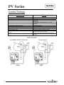
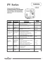
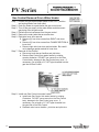
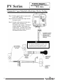
PV Series
Through-The-Wall Gas Water Heaters
SERVICE
MANUAL
Troubleshooting Guide
and Instructions for Service
(To be performed ONLY by
qualified service providers)
Models Covered
by This Manual:
RG1PV40S*(N,X)
RG1PV50S*(N,X)
RG1PV55H*(N,X)
RG2PV40T*(N,X)
RG2PV50H*(N,X)
RG2PV50T*(N,X)
RG2PV75H*(N,X)
LG1PV55H78*(N,X)
LG2PV50H65*(N,X)
LG2PV75H76*(N,X)
(*) Denotes Warranty Years
Manual 238-51540-00A 3/15
Save this manual for future reference
The Bradford White
PV Series
Through-The-Wall Gas Water Heaters
Table of Contents
Page
Introduction ................................................................................................................................ 4
---
How to Use This Manual .......................................................................................................... 5
---
Tools Required for Service ....................................................................................................... 5
---
Specifications ............................................................................................................................. 6
---
Control Timings ......................................................................................................................... 10
---
Sequence of Operation .............................................................................................................. 11
---
Troubleshooting ......................................................................................................................... 15
---
Burner Inspection, Cleaning & Replacement ......................................................................... 17
I
Pilot Testing, Cleaning & Replacement .................................................................................. 19
II
Pressure Switch Testing & Replacement ................................................................................ 20
III
Blower Testing & Replacement ............................................................................................... 22
IV
Blower Temperature Switch Testing & Replacement ........................................................... 24
V
Gas Control Testing & Replacement ....................................................................................... 26
VI
Flammable Vapor Device Testing and Replacement............................................................. 30
VII
Safety Circuit Voltage Trace .................................................................................................... 31
VIII
115 VAC Circuit Trace ............................................................................................................. 32
IX
Dip Tube Inspection & Replacement ...................................................................................... 33
X
Anode Inspection & Replacement ........................................................................................... 34
XI
Flue Baffle Inspection & Replacement.................................................................................... 35
XII
Inner Door Removal, Inspection & Replacement .................................................................. 36
XIII
Glossary of Terms ..................................................................................................................... 40
---
Parts List ..................................................................................................................................... 41
---
2
2
PV Service Procedure
PV Series
WARNING: If the information in these
instructions is not followed exactly, a fire or
explosion may result causing property damage,
personal injury, or death.
DANGER
Do not store or use gasoline or other flammable,
combustible, or corrosive vapors and liquids in
the vicinity of this or any other appliance.
WHATTODOIFYOUSMELLGAS!
x Donottrytolightanyappliance.
x Donottouchanyelectricalswitch;donotuseany
phoneinyourbuilding.
x Immediatelycallyourgassupplierfromaneighbor'sphone.
Followthegassupplier'sinstructions.
x Ifyoucannotreachyourgassupplier,callthefire
department.
Installationandservicemustbeperformedbyaqualified
installer,serviceagencyorthegassupplier.
IMPORTANT
Before proceeding, please inspect the
water heater and its components for
possible damage. DONOT install any
water heater with damaged
components. If damage is evident
then please contact the supplier where
the water heater was purchased or the
manufacturer listed on the rating plate
for replacement parts.
WARNING
Water heaters are heat producing appliances. To avoid damage
or injury, do not store materials against the water heater or ventair intake system. Use proper care to avoid unnecessary contact
(especially by children) with the water heater and vent-air intake
components. UNDER NO CIRCUMSTANCES MUST
FLAMMABLE MATERIALS, SUCH AS GASOLINE OR PAINT
THINNER BE USED OR STORED IN THE VICINITY OF THIS
WATER HEATER, VENT-AIR INTAKE SYSTEM OR IN ANY
LOCATION FROM WHICH FUMES COULD REACH THE
WATER HEATER OR VENT-AIR INTAKE SYSTEM
CAUTION
If sweat fittings are to be used DO NOT apply heat to the nipples
on top of the water heater. Sweat the tubing to the adapter
before fitting the adapter to the water connections. It is
imperative that heat is not applied to the nipples containing a
plastic liner.
WARNING
Hydrogen gas can be produced in an operating water heater that
has not had water drawn from the tank for a long period of time
(generally two weeks or more). Hydrogen gas is extremely
flammable. To prevent the possibility of injury under these
conditions, we recommend the hot water faucet to be open for
several minutes at the kitchen sink before you use any electrical
appliance which is connected to the hot water system. If
hydrogen is present, there will be an unusual sound such as air
escaping through the pipes as hot water begins to flow. Do not
smoke or have open flame near the faucet at the time it is open.
WARNING
DO NOT ATTEMPT TO LIGHT ANY GAS APPLIANCE IF YOU ARE
NOT CERTAIN OF THE FOLLOWING:
x
Liquefied petroleum gases/propane gas and natural gas
have an odorant added by the gas supplier that aids in the
detection of the gas.
x
Most people recognize this odor as a “sulfur” or “rotten egg”
smell.
x
Other conditions, such as “odorant fade” can cause the
odorant to diminish in intensity, or “fade”, and not be as
readily detectable.
x
If you have a diminished sense of smell, or are in any way
unsure of the presence of gas, immediately contact your gas
supplier from a neighbor’s telephone.
Gas detectors are available. Contact your gas supplier, or plumbing
professional, for more information.
WARNING
FAILURE TO INSTALL AND MAINTAIN A NEW, LISTED ¾” X ¾”
TEMPERATURE AND PRESSURE RELIEF VALVE WILL RELEASE
THE MANUFACTURER FROM ANY CLAIM THAT MIGHT RESULT
FROM EXCESSIVE TEMPERATURE AND PRESSURES.
CAUTION
Turn off or disconnect the electrical power supply to the water heater
before servicing. Label all wires prior to disconnection when servicing
controls. Wiring errors can cause improper and dangerous operation.
Verify proper operation after servicing.
3
3
PV Series
Introduction
The new Bradford White RG1PV & RG2PV water heaters are designed to provide reliable performance with
enhanced standard features. New design features include reliable spark to pilot ignition system, enhanced
diagnostics, simplified servicing, quiet operation, additional vent lengths, and Bradford White Defender
Safety System® (not available on all models).
Spark to Pilot Ignition System - employing the spark to pilot ignition system promotes reliable and consistent
pilot and main burner ignitions to provide hot water on demand.
Integrated Immersion Thermostat/Gas Control Valve with LED - was developed for ease of troubleshooting
by providing simple diagnostic codes to pinpoint an installation or component performance issue.
Powerful Blower - will eliminate problems with difficult venting situations.
Quiet and Cool Blower Operation - blower noise is significantly reduced for both interior and exterior
environments. Cooler operation increases blower life by reducing bearing wear and noise.
Rugged Wiring Connections - receptacle type connections promote error free wiring.
Increased Vent Lengths - increased venting performance is achieved while maintaining Energy Factor &
FHR (not available on all models) performance.
The RG1PV & RG2PV water heaters use a combustion system where flue gases are combined with dilution
air to reduce the flue gas temperature in the blower. The diluted flue gases are evacuated to the exterior
through low temperature vent materials. The gas control maintains water temperature, ignition sequence
and regulates gas flow. A safety circuit consisting of a pressure switch and blower temperature switch
verifies proper conditions exist for safe and reliable operation. If a situation outside of normal operating
parameters exists, the gas control diagnostic LED will flash a code to positively identify an operational issue.
This service manual is designed to facilitate problem diagnosis and enhance service efficiency.
Please read the service manual completely before attempting service on this new series of power vent
models.
How the Safety System Works
During normal operation, air for combustion is drawn into the water heater through the opening in the jacket.
This air travels down and around the combustion chamber and enters through holes in the very bottom of the
corrosion-resistant combustion chamber. The air then travels up through the oriented flame arrestor plate
louvers, where the velocity of air is increased and its direction altered. The air then mixes in a normal
manner with supplied gas and is efficiently combusted, producing low NOx emissions.
In the unlikely event trace amounts of flammable vapors are present in the air flowing into the combustion
chamber, the vapors are harmlessly ignited by the burner. If flammable vapors are in sufficient quantity to
prevent normal combustion, the flammable vapor sensor recognizes this and shuts down the pilot and main
burner. Should the flammable vapor continue to burn, the flame arrestor plate prevents the flames from
traveling backwards and igniting vapors outside of the combustion chamber. This feature is only on models
with inputs less than or equal to 75,000 BTU/hr.
4
4
PV Series
It is intended for this manual to be used by qualified service personnel for the primary purpose of
troubleshooting and repair of the Bradford White PV Series water heaters. Understanding the sequence of
operation section of this manual will contribute greatly to troubleshooting the water heater.
The Honeywell WV4462A Electronic Gas Control will display error codes in the event of abnormal operation.
Error codes are listed in the troubleshooting chart beginning on page 15 of this service manual. The
troubleshooting chart will also indicate the probable cause for the error code and direct the service
professional to a service procedure to properly diagnose the abnormal operation.
In some difficult to diagnose conditions, it may be necessary to isolate the heater from the vent system to
determine the problem.
Contact the Bradford White technical support group immediately if diagnosis cannot be made using the
methods described in this service manual.
Tools Required for Service
Manometer:
Multi-Meter:
Electronic Probes:
A liquid “U” tube type or a digital (magnahelic) type can be used. This
device is used to measure gas and/or air pressure and vacuum.
A digital type is strongly recommended. This device is used to measure
electrical values. The meter you select must have the capability to
measure volts AC, volts DC, Amps, micro-amps and ohms.
In some cases, standard multi-meter probes will damage or simply not be
effective to obtain certain voltage and ohm readings. It will be necessary to
have special electronic “pin” type multi-meter probes. These probes are
available at most electronic wholesale outlets.
Thermometer:
Used to measure water temperature. An accurate thermometer is
recommended.
Water Pressure Gage:
Used to measure water supply pressure. Also used to determine tank
pressure by adapting to the drain valve of the heater.
Various Hand Tools:
Pipe wrench, channel locks, open end wrenches (3/8”, 7/16”, 1/2”), 12”
crescent wrench, allen wrench set, screw drivers (common & Phillip’s), 1/4”
nut driver, pliers (common & needle nose), socket set, side cutters, wire
cutters, wire strippers, wire crimpers, torpedo level, small shop vac, step
ladder, flashlight and 5 gallon pail.
5
5
PV Series
Power supply
Gas Supply Pipe
Approved Gas
Type
Gas Pressure
Venting System
Approved Vent
Materials
Minimum
Clearance for
Servicing
Water Supply
Pressure
Gas Control
ECO Limit
Residential
Temperature Set
Point Range
Commercial
Temperature Set
Point Range
Blower
Temperature
Switch
Dedicated 115 VAC, 60 Hz, 15A.
Minimum 1/2” NPT (schedule 40 black iron pipe recommended).
Natural Gas or Propane, unit must match gas type supplied.
5.0” W.C. min. for Natural Gas, 11.0” W.C. min. for Propane, 14.0” W.C. maximum
(Natural Gas & Propane).
Power vent through the wall or vertical through the roof.
PVC, CPVC or ABS.
18” from top, 24” from front, 4” sides and rear.
150 PSI maximum allowable working pressure. Check local codes for supply
pressure.
Residential 188°F (87°C), Commercial 199°F (93°C).
60°F (16°C) to 160°F (71°C) (approximate temperatures).
80°F (27°C) to 180°F (82°C) (approximate temperatures).
Normally closed, opens @ 155°F (68°C), auto reset @ approximately 135°F (57°C).
RG1PV(40,50)S, (R,L)G2PV50H Models: Normally open, closes on vacuum increase
@ -.75” W.C.; Opens on vacuum decrease @ -.72” W.C.
RG2PV(40,50)T: Normally open, closes on vacuum increase @ -.80” W.C.;
Opens on vacuum decrease @ -.77” W.C.
Pressure Switch
(R,L)1PV55H Models: Normally open, closes on vacuum increase @ -1.40” W.C.;
Opens on vacuum decrease @ -1.37” W.C.
Blower
6
6
(R,L)G2PV75H Models: Normally open, closes on vacuum increase @ -1.25” W.C.;
Opens on vacuum decrease @ -1.22” W.C.
115 VAC, 60 Hz, 3.1 amps, 3000 RPM.
PV Series
Vent Tables
Venting Specifications for:
RG1PV40S, RG2PV40T
RG1PV50S, RG2PV50T
2" Diameter (5.1 cm) PVC Vent Connector Lengths
# of
Maximum Straight Minimum Straight
Terminating
Elbows
Length ft. (m)
Length ft. (m)
Through the Wall
1
45 (16.8)
2 (.6)
Through the Wall
2
40 (15.2)
2 (.6)
Through the Wall
3
35 (13.7)
2 (.6)
Through the Wall
4
30 (12.2)
2 (.6)
0
1
2
3
4
50 (18.3)
45 (16.8)
40 (15.2)
35 (10.7)
30 (9.2)
7 (2.1)
Through the Roof
Through the Roof
Through the Roof
Through the Roof
Through the Roof
7 (2.1)
7 (2.1)
7 (2.1)
7 (2.1)
3" Diameter (10.2 cm) PVC Vent Connector Lengths
# of
Maximum Straight Minimum Straight
Terminating
Elbows
Length ft. (m)
Length ft. (m)
Through the Wall
1
115 (35)
10 (3.1)
Through the Wall
2
110 (33.5)
10 (3.1)
Through the Wall
3
105 (32.0)
10 (3.1)
Through the Wall
Through the Wall
4
5
100 (30.5)
95 (29.0)
10 (3.1)
10 (3.1)
Through the Roof
Through the Roof
Through the Roof
Through the Roof
Through the Roof
0
1
2
3
4
120 (36.6)
115 (35)
110 (33.5)
105 (32.0)
100 (30.5)
15 (4.6)
15 (4.6)
15 (4.6)
15 (4.6)
15 (4.6)
7
7
PV Series
Vent Tables
Venting Specifications for:
RG2PV50H
LG2PV50H
3" Diameter (7.6 cm) PVC Vent Connector Lengths
# of
Maximum Straight Minimum Straight
Terminating
Elbows
Length ft. (m)
Length ft. (m)
Through the Wall
1
55 (16.8)
2 (.6)
Through the Wall
2
50 (15.2)
2 (.6)
Through the Wall
3
45 (13.7)
2 (.6)
Through the Wall
4
40 (12.2)
2 (.6)
Through the Roof
Through the Roof
Through the Roof
Through the Roof
0
1
2
3
60 (18.3)
55 (16.8)
50 (15.2)
45 (13.7)
7 (2.1)
7 (2.1)
7 (2.1)
7 (2.1)
4" Diameter (10.2 cm) PVC Vent Connector Lengths
# of
Maximum Straight Minimum Straight
Terminating
Elbows
Length ft. (m)
Length ft. (m)
8
8
Through the Wall
1
175 (53.3)
10 (3.1)
Through the Wall
2
170 (51.8)
10 (3.1)
Through the Wall
3
165 (50.3)
10 (3.1)
Through the Wall
Through the Wall
4
5
160 (48.8)
155 (47.2)
10 (3.1)
10 (3.1)
Through the Roof
Through the Roof
Through the Roof
Through the Roof
Through the Roof
0
1
2
3
4
180 (54.9)
175 (53.3)
170 (51.8)
165 (50.3)
160 (48.8)
15 (4.6)
15 (4.6)
15 (4.6)
15 (4.6)
15 (4.6)
PV Series
Vent Tables
Venting Specifications for:
RG1PV55H
RG2PV75H
LG1PV55H
LG2PV75H
3" Diameter (7.6 cm) PVC Vent Connector Lengths
# of
Maximum Straight Minimum Straight
Terminating
Elbows
Length ft. (m)
Length ft. (m)
Through the Wall
1
45 (13.7)
2 (.6)
Through the Wall
2
40 (12.2)
2 (.6)
Through the Wall
3
35 (10.7)
2 (.6)
Through the Wall
4
30 (9.1)
2 (.6)
Through the Roof
Through the Roof
Through the Roof
Through the Roof
0
1
2
3
50 (15.2)
45 (13.7)
40 (12.2)
35 (10.7)
7 (2.1)
7 (2.1)
7 (2.1)
7 (2.1)
4" Diameter (7.6 cm) PVC Vent Connector Lengths
Minimum
Maximum
# of
Straight
Straight
Terminating
Elbows
Length ft. (m)
Length ft. (m)
Through the Wall
1
175 (53.3)
10 (3.1)
Through the Wall
2
170 (51.8)
10 (3.1)
Through the Wall
3
165 (50.3)
10 (3.1)
Through the Wall
Through the Wall
4
5
160 (48.8)
155 (47.2)
10 (3.1)
10 (3.1)
Through the Roof
Through the Roof
Through the Roof
Through the Roof
Through the Roof
0
1
2
3
4
180 (54.9)
175 (53.3)
170 (51.8)
165 (50.3)
160 (48.8)
15 (4.6)
15 (4.6)
15 (4.6)
15 (4.6)
15 (4.6)
9
9
PV Series
Control Timings
Ignition State
Pre-purge
Trial for Ignition
Flame Stabilization Period
Inter-purge
Flame Failure Response Time
Post-purge
PS Fault Delay (failed open/close)
Soft Lockout
ECO Limit Lockout
Verify Resistive Delay
Flammable Vapor Sensor/Simulated Resistive Load
Lockout
Hardware Error Lockout
10
10
Timing
2 Seconds
90 Seconds
3 Seconds
15 Seconds
1.5 Seconds (2 second maximum; 1 second
minimum.)
15 Seconds
Retry after 2 minutes
Retry after 5 minutes
Indefinite (see page 27)
Retry after 2 minutes (repeats 5 times)
Indefinite (cycle power to restart)
Indefinite (self clears if fault clears for at least 15
seconds)
PV Series
Power Up Sequence
1. Start Up.
Upon power up, the control runs a safe-start check with a typical start-up delay of 5
seconds.
2. Flammable Vapor.
To assure no outputs are energized if the “Flammable Vapor Sensor” (for
RG1PV40S, RG1PV50S, RG2PV40T, RG2PV50T, RG2PV50H) or “Simulated
Resistive Device” (for RG1PV55H and RG2PV75H) is out of range, the control will
test the “Flammable Vapor Sensor” or “Simulated Resistive Device” for proper
operating range. If the “Flammable Vapor Sensor” or “Simulative Resistive Device”
is out of range, the control LED immediately flashes 7 times with 3 second pause.
Normal Heating Sequence
1. Thermostat calls for heat.
Prior to energizing blower, gas control checks safety circuit to ensure the circuit is
open. Normal switch positions in the safety circuit are as follows:
a) Pressure switch normally open.
b) Blower temperature switch normally closed.
If the safety circuit is closed, the control waits 4 seconds, gas control LED
flashes 2 times with 3 second pause. Gas control waits 2 minutes then,
blower runs for 30 seconds. This cycle repeats until safety circuit opens.
2. Blower energizes.
3. Pressure switch proves blower/vent system operation.
If the pressure switch does not close within 30 seconds, the control LED flashes 3
times with 3 second pause. The blower runs for 30 seconds every 2 minutes trying
to get the pressure switch or blower temperature switch to close. This cycle repeats
as long as there is a call for heat.
4. Blower pre-purge period (2 seconds).
5. Trial for pilot ignition (90 seconds).
a. The gas control lights the pilot by activating spark igniter and gas flow to pilot
burner.
b. If flame is not sensed within 90 seconds, igniter and gas flow are
deactivated, blower will post purge and control LED flashes 6 times with 3
second pause.
6. Main burner ignition.
After pilot flame is sensed, gas control activates main valve for main burner ignition.
The gas control will ignore flame and pressure switch signals for 3 seconds allowing
for main burner to stabilize.
11
11
PV Series
Normal Heating Sequence (cont.)
7. Steady state operation.
During steady state operation, the control monitors:
Thermostat temperature sensor-when set point temperature is satisfied, gas
valve is shut down and blower will post purge for 15 seconds. Control LED flashes
a short flash once every 4 seconds (idle) status code.
Pressure switch / blower temperature switch-if either switch opens, the pilot
valve and the main valve are both shut down. The blower continues to run for 30
seconds attempting to close the circuit. The control LED flashes 3 times with 3
second pause.
Flame sensor-if flame is lost, pilot & main valves are shut down, blower runs for 15
seconds. Control attempts to re-light pilot 4 times. If unsuccessful, blower is shut
down and control proceeds to 5 minute lockout. Control re-attempts to light pilot
starting at normal heating sequence #2.
8. Thermostat satisfies. (Control LED flashing once every 4 seconds).
9. Burner off.
10. Blower post purges (15 seconds).
Abnormal Operation
1. Flammable Vapor Sensor or Simulated Resistive Device Fault:
a. If the resistance is greater than 70,000 Ohms-the gas control immediately
turns off all outputs. Control waits and monitors resistance for 30 seconds.
If the resistance is greater than 65,000 ohms after 30 seconds, the gas
control proceeds to verify resistive delay for 2 minutes and flashes 7 times
then once with a three second pause. This process is repeated 5 times until
the control either returns to normal operation or proceeds to flammable vapor
lockout.
b. If the resistance is below 3000 Ohms-The gas control immediately turns
off all outputs and proceeds to flash 8 times then once with three second
pause. The error self clears if the resistance returns to normal range for at
least 15 seconds.
2. Temperature Sensor Fault:
a. Temperature sensor detected open circuit–The gas control immediately
turns off all outputs and proceeds to flash 8 times then, 3 times with 3
second pause. The error self clears if the fault clears for at least 15 seconds.
b. Thermal well sensor not reading the same temperature within ±5.5°F –
The gas control immediately turns off all outputs and proceeds to flash 8
12
12
PV Series
Abnormal Operation (cont.)
times, then 3 times twice with 3 second pauses. The error self clears if the
fault clears for at least 15 seconds.
c. Water temperature in excess of ECO (energy cut out) limit -The gas
control immediately turns off pilot & main valves and proceeds to flash 4
times with 3 second pause. Blower continues to run until gas control is reset.
To reset control, rotate knob of temperature control to the minimum setting
for at least 6 seconds before returning to desired temperature setting.
3. Pressure Switch/Blower Temperature Fault:
a. Pressure switch closed at start of call for heat-the gas control waits 4
seconds then, proceeds to flash 2 times with 3 second pause. The control
waits 2 minutes and then turns on blower for 30 seconds. The blower turns
off after 30 seconds and the control waits for pressure switch to open. Any
time the pressure switch opens, the blower turns on (or stays on) and the
control proceeds to wait for pressure switch to close.
b. Pressure switch or blower temperature switch failed to close-the gas
control runs the blower for 30 seconds waiting for the pressure switch and/or
blower temperature switch to close. If either switch does not close in 30
seconds, the blower turns off and the control flashes 3 times with 3 second
pause. The gas control waits 2 minutes before turning on the blower for
another 30 seconds to see the circuit close. This cycle repeats as long as
there is a call for heat or until the circuit closes.
c. Pressure switch or blower temperature switch opens during burner
operation-the gas control turns off the pilot and main valve, runs blower for
15 seconds (inter-purge) waiting for pressure switch and/or blower
temperature switch to close. If either switch fails to close, the control
proceeds as described in 3b above, if the circuit closes again by the end of
the inter-purge, the recycle counter is incremented, if the recycle count has
not reached its limit (4), another trial for ignition begins. If the recycle count
has been reached, the gas control turns off the blower and flashes 6 times
then, 2 times with 3 second pause. The gas control waits 5 minutes before
repeating ignition sequence.
4. Trial for Ignition Fault:
a. Pressure switch opens during trial-the gas control turns off igniter and
pilot valve. The gas control proceeds as described in 3b above. If the
pressure switch closes within 30 seconds the gas control will continue with
trial for ignition starting at blower pre-purge.
b. Flame not sensed-the gas control energizes the spark igniter attempting to
light the pilot and prove flame. If flame is not sensed within 90 seconds, the
igniter turns off, the pilot valve is closed and the gas control runs the blower
through post purge and flashes 6 times then, once with 3 second pause.
The control waits 5 minutes before repeating the ignition sequence.
13
13
PV Series
Abnormal Operation (cont.)
5. Flame sensing fault:
a. Flame lost during run-the gas control turns off pilot and main valves, runs
blower for 15 seconds (inter-purge). The gas control increments the recycle
count, if the recycle count has not reached its limit (4), another trial for
ignition begins. If the recycle count has been reached, the gas control turns
off the blower and flashes 6 times then, 3 times with 3 second pause. The
gas control waits 5 minutes before repeating the ignition sequence.
b. Flame sensed out of sequence-the gas control only looks for pilot flame
when the blower is running. If flame is present when the pilot valve is not
open, the gas control proceeds to wait for flame loss and flashes 5 times with
3 second pause. This continues until flame is lost. Once the flame signal is
lost, the control flashes 6 times then, 4 times with 3 second pause. The
control waits 5 minutes before repeating the ignition sequence.
14
14
PV Series
Observe green LED indicator on
electronic gas control. Error flash codes
are displayed with a three second pause
before repeating. Check and repair the
system as noted in the troubleshooting
table below.
LEDStatus
None, control
LED not on or
flashing
Short flash, once
every four
seconds
“Heartbeat”
alternates
bright/dim
ControlStatus
No electrical
power
Stand-by mode,
Waiting for call
for heat (no fault).
Thermostat
calling
for heat (no fault).
Short flash once
per second
Weak pilot signal
on last call for
heat.
Two flash, three
second pause
Pressure switch
not workingclosed position.
Three flash,
three second
pause
Four flash, three
second pause
Five flash, three
second pause
Pressure switch
or blower temp.
switch not
working -open
position.
Excessive tank
temperature.
System must be
reset.
Undesired-false
pilot flame
present.
ProbableCause
Control power switch in “OFF” position.
Supply voltage interrupted.
Temperature demand is satisfied
Tank temperature below set point of
thermostat.
1. Unstable pilot.
2. Pilot tube block or restricted.
3. Oxidation build up on pilot electrode.
4. Wire damage to pilot assembly or bad
connection at gas valve.
1. Pressure switch tubing kinked or blocked.
2. Blocked pressure tap on switch or blower.
3. Faulty pressure switch.
1. Vent blockage or improper vent
configuration.
2. Pressure switch tubing kinked or blocked.
3. Faulty pressure switch.
4. Blower not spinning up to speed.
5. Blower temp or exhaust temp too high.
6. Faulty blower temperature switch.
Service
Procedure
Turn power on
Normal operation.
Adjust thermostat to
temp level.
Normal operation.
Adjust thermostat to
temp level.
Page 19
Page 20
1. Check vent or vent
tables.
2 & 3 Page 20
4. Page 22
5 & 6 Page 24
1. Temperature sensor out of calibration.
2. Faulty gas control.
3. Plumbing leak.
1 & 2. Replace gas
control,
page 28
1. Pilot valve stuck in open position.
Replace gas control,
page 28
15
15
PV Series
LEDStatus
ControlStatus
ProbableCause
Service
Procedure
Six-one
flash, three
second
pause
Failed to light
pilot.
System auto
resets.
1. Unstable pilot.
2. Pilot tube blocked or restricted.
3. Oxidation build up on pilot electrode.
4. Wire damage to pilot assembly or bad
connection at gas valve.
Six-two flash,
three second
pause
Pressure switch
or blower temp
switch opened
during burner
operation.
System auto
resets.
1. Vent blockage or improper vent configuration.
2. Pressure switch tubing kinked or blocked.
3. Faulty pressure switch.
4. Vent termination being affected by wind.
5. Blower not spinning up to speed.
6. Blower temp or exhaust temp too high.
7. Faulty blower temperature switch.
Pilot flame
extinguished.
System auto
resets.
1. Unstable pilot.
2. Pilot tube blocked or restricted.
3. Oxidation build up on pilot electrode.
4. Wire damage to pilot assembly or bad
connection at gas valve.
5. Insufficient combustion air.
6. Gas pressure is out of specification.
5. Refer to installation
manual
Pilot valve stuck in open position.
Replace gas control,
page 28
Flammable vapor sensor or simulative resistance
device out of specification.
Page 30
Flammable vapor
sensor out of
specification.
Flammable vapor sensor or simulated resistive
device out of specification.
Page 30
Temperature
Sensor fault.
1. Damage to temperature sensor wire.
2. Temperature sensor resistance out of range.
Replace gas control,
page 28
Gas valve
electronics fault
detected.
1. Control needs to be reset.
2. Control is wet or physically damaged.
1. Interrupt power supply
2. Replace gas control,
page 28
Gas valve fault
detected.
1. Control needs to be reset.
2. Control is wet or physically damaged.
1. Interrupt power supply
2. Replace gas control,
page 28
Page 19
1. Check vent or vent tables.
Six-three
flash, three
second
pause
Six-four
flash, three
second
pause
Seven flash,
three second
pause
Eight-one
flash, three
second
pause
Eight-two
flash, three
second
pause
Eight-three
flash, three
second
pause
Eight-four
flash, three
second
pause
16
16
Undesired-false
pilot flame
sensed.
System auto
resets.
Flammable vapor
sensor fault
detected.
2 & 3 Page 20
4. Refer to venting section of
installation manual
5. Page 22
6 & 7 Page 24
1-4. Page 19
6. Page 26
PV Series
Burner Inspection
At periodic intervals (every 6 months) a visual inspection should be made of the pilot and main
burner for proper operation and to assure no debris is accumulating.
Pilot flame should be stable, some causes for an unstable pilot flame are:
a) Water heater vent is less than the allowable vent length.
b) Gas pressure is out of specification.
c) Pilot flame not fully engulfing spark/flame sensor.
Main burner should light smoothly from pilot and burn with a blue flame with a minimum of yellow
tips.
Main burner must be free from any debris accumulation that may affect burner operation (see
burner cleaning procedure on page 18).
17
17
PV Series
Burner Cleaning
Step 1.
Step 2.
Step 3.
Step 4.
Step 5.
Step 6.
Step 7.
Step 8.
Position gas control power
switch to the “OFF” position and
unplug heater from wall outlet.
Turn off gas supply to water
heater.
Remove outer jacket door and
inner door per service
procedure XIII on page 36.
Disconnect pilot tube (7/16” wrench)
and feedline (3/4” wrench) from gas
control.
Disconnect igniter/flame sensor wire from gas control.
Remove burner assembly from combustion chamber.
Thoroughly inspect burner surface area and burner port area and remove
any loose debris.
Unscrew burner from main burner orifice.
NOTICE
Feedline nut for natural gas control
uses right hand threads, LP control
uses left hand thread.
Step 9.
Remove main burner orifice from
feedline (1/2” wrench on steel
burners) inspect orifice, clean or
replace if necessary.
Step 10. Reassemble burner and reinstall
into water heater. Restore gas
supply and check for gas leaks.
Step 11. To resume operation, follow the instruction located on the lighting
instruction label or the lighting instruction located in the installation and
operation manual.
18
18
PV Series
Pilot Inspection, Testing and
Replacement
Step 1.
Position gas control power
switch to the “OFF” position
and unplug heater from wall
outlet.
Step 2.
Turn off gas supply to water
heater.
Step 3.
Remove outer jacket door and inner door per
service procedure XIII on page 36.
Step 4.
Disconnect pilot tubing nut (7/16” wrench) and
feedline nut (3/4” wrench) from gas control.
Step 5.
Disconnect igniter/flame sense wire from gas control.
Step 6.
Remove burner assembly from combustion chamber.
Step 7.
Remove pilot assembly from feedline (1/4” nut driver).
Step 8.
Visually inspect igniter/flame sense wire for damage. Replace pilot if damage
is found.
Step 9.
With a multi-meter set to ohms setting,
check continuity through igniter/flame
sense wire. Replace pilot if no continuity.
Step 10. Visually inspect igniter/flame sense
electrode for deterioration. Replace pilot
as necessary. Electrode should not be in
contact with pilot hood, if so, carefully
adjust electrode to a gap of distance of
3/32” (.09) from pilot hood.
Step 11. Visually inspect igniter/flame sense
electrode for oxidation build up. Carefully
clean any oxidation using very fine emery
cloth.
Step 12. Visually inspect pilot tubing for kinks or
cracks. If damage is found, replace pilot.
Step 13. Inspect pilot tubing and pilot orifice for
blockage:
a. Remove ferrule nut from bottom of pilot
assembly (7/16” wrench).
b. Remove pilot tube and pilot orifice.
c. Inspect pilot tubing and pilot orifice for blockage. Clean or replace as
necessary.
Step 14. Reassemble pilot and install on feedline. Reinstall burner assembly to water
heater. Restore gas supply and check for gas leaks.
19
19
PV Series
Step 15.
To resume operation, follow the instructions located on the lighting
instruction label or the lighting instructions located in the installation and
operation manual.
Pressure Switch Testing
Step 1.
Step 2.
Step 3.
20
20
WARNING
115 volt potential exposure. Use
caution to avoid personal injury.
Position power switch on gas
control to the “OFF” position.
Remove the three screws (Phillips screw driver) from control access cover
on blower assembly and remove cover (see photo 1).
Carefully remove pressure switch from blower housing (see photo 2).
PV Series
Pressure Switch Replacement
WARNING
Position gas control power
115
volt
potential
exposure. Use
switch to “OFF” position.
caution
to
avoid
personal
injury.
Step 2. Remove the three screws
(Phillip’s screw driver) from
control access cover on blower
assembly and remove cover
(see photo 3).
Step 3. Carefully remove pressure switch from blower housing (see photo 4).
Step 4. Disconnect tubing from pressure switch. (see photo 5).
Step 5. Disconnect yellow wires from pressure switch (see photo 6).
Step 6. Reconnect wires from step 6 to new pressure switch.
Step 7. Reconnect tubing to new pressure switch.
Step 8. Carefully position pressure switch into blower housing.
Step 9. Position gas control power switch to “ON” position and verify proper heater
operation.
Step 10. Replace control access cover from step 2.
Step 1.
21
21
PV Series
Blower Testing
Step 1.
Step 2.
22
22
Position gas control
power switch to “ON”
position and adjust control
to call for heat.
Remove the three screws
(Phillip’s screw driver) from
control access cover on blower
assembly and remove cover (see
photo 7).
WARNING
115 volt potential exposure. Use
caution to avoid personal injury.
PV Series
Blower Removal
Step 1. Position gas control power switch to “OFF” position and adjust control to
call for heat.
Step 2. Unplug blower power cord from wall
outlet.
Step 3. Disconnect vent system from exhaust
adapter on top of blower.
Step 4. Remove exhaust adapter from blower
(blade screw driver) and retain for use
on new blower.
Step 5. Unplug cord sets from blower.
Step 6. Remove the three blower mounting
screws (1/4” nut driver).
Step 7. Remove blower with gasket from
water heater.
Blower Installation
Step 8.
Step 9.
Step 10.
Step 11.
Step 12.
Step 13.
Step 14.
Step 15.
Step 16.
Clean any debris from jacket head
of water heater.
Set new blower with gasket in
place using locating pins on
blower flange to line up with
location holes in jacket head. Be
sure not to damage gasket.
Secure blower in place using
mounting screws from step 6.
Re-install exhaust adapter from
step 4.
Reconnect vent system to exhaust
adapter.
Reconnect cord sets from step 5.
Plug blower power cord into wall
outlet.
Position gas control power switch
to the “ON” position.
Verify proper blower operation.
23
23
PV Series
Blower Temperature Switch
Testing
Position power switch on gas control to the
“OFF” position.
Step 1.
Step 2.
24
24
Remove the three screws (Phillip’s
screw driver) from control access
cover on blower and remove cover
(see photo 14).
Locate blower temperature switch
(see photo 15).
WARNING
115 volt potential exposure. Use
caution to avoid personal injury.
PV Series
Blower Temperature Switch
Replacement
WARNING
115 volt potential exposure. Use
caution to avoid personal injury.
Step 1. Position gas control power switch to
the “OFF” position and unplug heater
from wall outlet.
Step 2. Remove the three screws (Phillip’s
screw driver) from the control access
cover on blower and remove cover
(see photo 16).
Step 3. Locate blower temperature switch
(see photo 17).
Step 4. Disconnect red and yellow wire leads
from switch.
Step 5. With an appropriate tool such as side
cutters, snip the retaining lug from the
blower housing to allow removal of
temperature switch (see photo 18).
Step 6. Remove switch from blower housing.
Step 7. Install new switch. Be sure switch is
properly seated in mounting area.
Step 8. Reconnect red and yellow wires to
new switch. Wires are
interchangeable with either terminal.
Step 9. Position gas control power switch to
the “ON” position and verify proper
heater operation.
Step 10. Replace control access cover from
step 2.
25
25
PV Series
Line Pressure
The gas control is designed for a maximum line pressure of 14.0” W.C. and a minimum
line pressure of 1.0” W.C. over the water heater’s rated manifold pressure (check rating
plate). Line pressure must be checked with the main burner on and off to assure proper
readings.
Manifold Pressure Testing
(this procedure presumes a maximum
line pressure of 14.0” W.C.)
Step 1. Set the Gas Control to the “OFF” position.
Step 2. Remove pressure tap plug and install 1/8”
NPT pipe, coupling & pressure tap.
Step 3. Connect manometer to pressure tap.
Step 4. Follow instructions located on the lighting
instructions label and proceed to light the
main burner and observe manometer
reading.
Step 5. Proper operating range for Natural Gas is
4.0” ±0.5” W.C. Proper operating range
for Propane gas is10.0” ±0.5” W.C.
Step 6. If pressure is within the range specified in
the previous step, set Gas Control knob to
the “OFF” position, remove manometer
and pressure tap, and replace pressure
tap plug. Check for gas leaks prior to
placing water heater back into operation
by following the instructions located on
the lighting label, or the lighting
instructions located in the installation and
operation manual.
Step 7. If gas pressure is outside the specification
noted above, refer to “Honeywell Gas
Control Testing, Disassembly and
Replacement” to replace gas control or
valve body.
26
26
PV Series
Determine Water Temperature Inside Tank
WARNING
Stored water may be HOT WHEN PERFORMING THE FOLLOWING STEPS IN
THIS PROCEDURE. Take necessary precaution to prevent personal injury.
Step 1. Position gas control power switch to “OFF” position.
Step 2. Draw approximately 4 gallons of water from the drain valve into a container
and discard. Draw an additional gallon and immediately measure water
temperature using an accurate thermometer (It may be necessary to open
a hot water faucet to allow heater to drain).
Step 3. Compare the measured water temperature with the setting on the gas
control. In most instances, they should not differ by more than apporx.
10°F.
27
27
PV Series
Gas Control Removal From Water Heater
Step 1. Position the gas control power switch to the “OFF” position
and unplug heater from wall outlet.
Step 2. Drain the heater to a point below the gas control level.
Step 3. Turn off the gas supply to the water heater and disconnect
gas piping from the gas control.
Step 4. Disconnect wire harnesses from the gas control.
Step 5. Remove the outer jacket burner access door.
Step 6. Right side inner door removal.
a. Remove (2) hex drive screws from RIGHT side inner
door.
b. Remove (2) hex drive screws from FLANGE SECTION of
inner door.
c. Remove right side inner door and set aside. Be careful
not to damage gasket material in inner door.
Step 7. Removal of Gas Control
a. Disconnect main burner feedline and pilot tube.
b. Remove Gas Control from water heater by rotating
counter clockwise. DO NOT use a wrench on the Gas
Control body, damage to the Gas Control may occur. If
necessary, use a length of ½” NPT pipe threaded into the
gas inlet of Gas Control.
Step 8. Install new Gas Control into water heater.
a. Install new Gas Control into water heater by rotating
Clockwise. DO NOT use a wrench on the Gas Control
body, damage to the Gas Control may occur. If
necessary, use a length of ½” NPT pipe threaded into
the gas inlet of the Gas Control.
b. Reattach main burner feedline , pilot tube and pilot wire.
28
28
PV Series
Reinstallation of inner door assembly.
c.
Prior to reinstallation of inner door, fully inspect for the
following:
-Tears
-Other imperfections that will inhibit proper seal
-Missing material
-Gasket adhesion to inner door
-Cracks
-Material left on combustion chamber (around opening)
-Dirt or debris
If the gasket is not affected by any of the above, gasket replacement may not be
required. If replacement is required, replace using new gasket kit following the
instructions provided with
d.
Clean any gasket residue or other debris from combustion chamber surface
before installing the inner door/gasket assembly.
Position the spark igniter wire and pilot tube against left side inner door flange
e.
gasket. DO NOT ROUTE THROUGH RADIUSED CHANNEL WITH FEEDLINE.
Be sure that the spark igniter wire and pilot tube are not in position to interfere
with outer jacket burner access door when reinstalled.
f.
Firmly place right side inner door flange against the left side inner door flange
and secure with (2) hex drive screws from step 6b. DO NOT OVER TIGHTEN
SCREWS.
g.
Align right side inner door to combustion chamber and verify the fastener holes of
the combustion chamber are aligned with the right side inner door slotted
openings. Verify seal integrity around combustion chamber opening. Secure
right side inner door using (2) hex drive screws from step 6a. DO NOT OVER
TIGHTEN SCREWS. Verify both left and right sides of the inner door are
properly positioned and sealed against the combustion chamber.
CAUTION
A seal breach may result in a fire or explosion causing
property damage, personal injury or death.
Step 9. Replace outer jacket burner access door.
Step 10.Reconnect gas supply to Gas Control.
Step 11.Resume water supply to water heater. Be sure tank is full of water before
resuming operation.
Step 12.To resume operation follow the instructions located on the lighting instruction
label or the lighting instructions located in the installation and operation manual.
29
29
PV Series
Flammable Vapor/Simulative Resistance Device Testing
Step 1. Position power switch on gas control
to the “OFF” position.
Step 2. Disconnect flammable vapor sensor
from gas control.
Step 3. Using a multi-meter set to the ohms
setting, check resistance of
flammable vapor sensor. Resistance
must be between 3,000 ohms and
48,000 ohms. If outside of this range
replace Flammable Vapor Sensor or
Simulated Resistive Device.
CAUTION
DO NOT use a standard multi-meter probe for this
test. Doing so will damage connector. Use
special pin type electronic probes or small
diameter wire pins inserted into connector.
30
30
PV Series
Safety Circuit Voltage
Trace
WARNING
115 volt potential exposure. Use
caution to avoid personal injury.
NOTE:Thisprocedureassumesacooltank.
Removethreescrews(PhillipsScrewdriver)fromcontrol
accesscoveronblowerandremovecover(seephoto19).
31
31
PV Series
115 VAC Circuit Trace
Step1.
Step2.
32
32
Verify115VACandproperpolarity
atwalloutlet.
Withunitpluggedinandcontrol
powerswitchinthe“ON”position
verifyLEDstatus.
WARNING
115 volt potential exposure. Use
caution to avoid personal injury.
PV Series
Diptube Inspection & Replacement
Step 1.
Step 2.
Step 3.
Step 4.
Step 5.
Step 6.
Step 7.
WARNING
Water Heater components and stored water may be HOT when performing the
following steps in this procedure. Take necessary precaution to prevent
personal injury.
Position on/off switch of gas control valve to “OFF” position and unplug water heater from wall
outlet.
Turn off cold water supply to water heater. Connect hose to drain valve of water heater and
route to an open drain. Open a nearby hot water faucet to vent heater for draining. Open drain
valve of water heater and allow heater to drain to a point below the inlet connection nipple.
Disconnect inlet nipple from plumbing system.
With an appropriate tool such as a pipe wrench, remove inlet nipple/dip tube from the water
heater. Use caution not to damage pipe threads.
Visually inspect inlet nipple/dip tube. Inlet nipple/dip tube should be free of cracks and any
blockage. Hydrojet slots should be open and free of any blockage. Any damage such as
cracks, restriction due to deformation or unintentional holes are not field repairable and the inlet
nipple/dip tube must be replaced.
Upon completion of inspection or subsequent replacement, reinstall inlet nipple/dip tube into
water heater. Connect nipple to plumbing system, resume water supply and refill with water.
To resume operation follow the instructions located on the lighting instruction label or the lighting
instructions located in the installation and operation manual.
33
33
PV Series
Anode Inspection & Replacement
WARNING
Water Heater components and stored water may be HOT when performing the
following steps in this procedure. Take necessary precaution to prevent
personal injury.
Step1.
Step2.
Step3.
Step4.
Step5.
Step6.
Step7.
34
34
Position on/off switch of gas control valve to the “OFF” position and unplug water heater from
wall outlet. Turn off cold water supply to water heater. Connect hose to drain valve of water heater and
route to an open drain. Open a nearby hot water faucet to vent water heater for draining.
Open drain valve of water heater and allow water heater to drain to a point below the outlet
connection nipple.
Disconnect outlet nipple from plumbing system.
With an appropriate tool such as a pipe wrench, remove outlet nipple/anode from the water
heater. Use caution not to damage pipe threads.
Visually inspect outlet nipple/anode. Outlet nipple/anode should show signs of depletion, this
is normal. If depletion is ½ of the original anode diameter (approximately ¾” diameter),
replacement is recommended. If any of the steel core of the anode is exposed, replacement is
recommended.
Upon completion of inspection or subsequent replacement, reinstall outlet nipple/anode into
water heater. Connect nipple to plumbing system, resume water supply and refill with water.
To resume operation, follow the instructions located on the lighting instruction label or the
lighting instructions located in the installation and operation manual.
PV Series
Flue Baffle Inspection and Replacement
Step 1.
Step 2.
Step 3.
Step 4.
Step 5.
Step 6.
Step 7.
Step 8.
Step 9.
Step 10.
Step 11.
Position gas control power switch to the
“OFF” position and unplug blower from wall
outlet.
Disconnect vent system from exhaust
adapter on top of blower.
Unplug cord sets from blower
(see photo 26).
Remove the three blower
mounting screws (1/4” nut driver)
(see photo 26).
Remove blower with gasket from water heater.
Remove flue baffle or flue core from heater (see photos
27a and 27b).
Inspect baffle or core for deterioration, missing restrictors.
Clean any scale or debris build up. Replace with new
baffle or core as necessary.
Reinstall baffle or core into flue tube. Be sure hanger tabs are inserted into
notch location at the top of the flue tube (see photos 28 & 29).
Check burner to insure no scale has accumulated during this operation. See burner
cleaning procedure on page 18.
Reinstall blower on water heater. Connect vent system and cords set to blower. Plug
water heater into wall outlet.
To resume operation
follow the lighting
instruction located on
the lighting instruction
label or the lighting
instruction located in the
installation operation
manual.
35
35
PV Series
Inner Door Removal Procedure
Step 1. Position gas control power switch to the “OFF”
position.
Step 2. Remove outer jacket burner access door.
Step 3. Inner Door removal.
a.
Remove (2) ¼” hex drive screws from right side inner door.
b.
Remove (2) ¼” drive screws from flange section of inner door.
c.
Remove (2) ¼” drive screws from left side inner door.
d.
Remove inner door and inspect per step 4.
Step 4.
Fully inspect inner door gaskets for the
following:
-Tears
-Other imperfections that will inhibit proper seal
-Missing Material
-Gasket adhesion to inner door
-Cracks
-Material left on combustion chamber (around opening)
-Dirt or debris
If the gasket is not affected by any of the above, gasket replacement is not required. If replacement is
required, proceed to Inner Door Gasket Replacement Procedure.
Inner Door Gasket Replacement Procedure
WARNING
If the information in these instructions is not followed exactly, a
fire or explosion may result causing property damage, personal
injury or death.
Step 5.
Step 6.
36
36
After inspection of inner door as noted in step 4, completely remove gasket and adhesive residue
from right and left side inner doors as needed.
Use RTV sealant (recommended bead size 1/8”) to secure the inner door gasket to the inner door
sections (right & left). Refer to illustration on next page for proper application. Note the overlap
configuration in the flange area of the inner door. Set the flange section first, this will help to
achieve the proper overlap position.
PV Series
Installation of Inner Door With Gasket
Step 7.
Step 8.
Step 9.
Clean any residual gasket residue or other debris from
combustion chamber surface before installing the inner
door/gasket assembly.
Place the left side inner door into position first. Firmly
position the radiused channel of the inner door around
the feedline. Using the ¼” hex drive screws from step
3c, secure left side inner door in place. DO NOT
OVER TIGHTEN SCREWS
Position pilot tube and igniter/sensor wire against left
side inner door flange gasket. DO NOT ROUTE
THROUGH RADIUSED CHANNEL WITH FEEDLINE.
WARNING
Stripped fastener connections
may allow for seal breach of
inner door. A seal breach may
result in a fire or explosion
causing property damage,
personal injury or death. Do
not over tighten screws in
steps 8, 10 and 11.
37
37
PV Series
Installation of Inner Door With Gasket (cont.)
Step 10.
Firmly place right side inner door flange against the left side inner door flange and secure
with (2) ¼” hex drive screws from step 3b. DO NOT OVER TIGHTEN SCREWS.
Step 11.
Align right side inner door to combustion chamber and verify the fastener holes of the
combustion chamber are aligned with right side inner door slotted opening. Verify seal
integrity around combustion opening. Secure right side inner door using ¼” hex drive screws
from step 3a. DO NOT OVER TIGHTEN SCREWS. Verify both left and right sides of inner
door are properly positioned and sealed against the combustion chamber.
Step 12.
Step 13.
38
38
Replace outer jacket burner access door.
To resume operation follow the instructions located on the lighting instruction label or the lighting
instructions located in the installation and operation manual.
PV Series
ScreenLok® Flame Arrestor Cleaning
Step 1.
Step 2.
Step 3.
Step 4.
Step 5.
Step 6.
Step 7.
Step 8.
Step 9.
NOTICE
Some models are not equipped with the
ScreenLok® Flame Arrestor.
Position Gas Control power switch to the “OFF” position.
Remove outer door.
Remove outer jacket door and inner door per service procedure XIII on page 36.
Disconnect main burner feedline (3/4” wrench), pilot tube (7/16” wrench) and
igniter/flame sensor wire from gas control and remove burner assembly from
combustion chamber.
Clean ScreenLok® Flame Arrestor using stiff brush, compressed air and/or shop
vacuum to remove any scale or other debris accumulation. Using a soft brush,
clear jacket openings from any dirt, dust, restrictions or other obstructions.
Remove any debris from burner assembly per PROCEDURE I and reinstall
burner assembly into combustion chamber.
Reconnect feedline, pilot tube and igniter/flame sensor wire to the gas control
Reinstall outer jacket door and inner door per service procedure XIII on page 36.
To resume operation follow the instructions located on the lighting instruction
label or the lighting instruction located in the installation and operation manual.
39
39
PV Series
Frozen Exhaust Vent Terminal
If an exhaust vent terminal is blocked with ice or snow due to severe conditions, the pressure switch
and control will not allow the burner to operate. This will result in a three flash error code. Once the blockage is
removed (through melting or other means) the controls will let the burner operate. The position of the vent
terminals in relation to each other and terminals from other appliances can have an effect on the potential for
blockage due to ice or snow. See the installation instructions for recommended positioning of the terminals.
Glossary of Terms
BTU
GPM
Hz
kWhr
LED
NPT
Ohms
PSI
RPM
ECO
VAC
“ W.C.
ºC
ºF
40
40
British Thermal Units
Gallons per Minute
Hertz
Kilowatt Hour
Light Emitting Diode
National Pipe Thread
Ohms of resistance
Pounds per Square Inch
Revolutions per minute
Energy Cut Out
Volts Alternating Current
Inches of Water Column
Degrees Centigrade
Degrees Fahrenheit
PV Series
1.
2.
3.
4.
5.
6.
7.
8.
9.
Blower Complete
Air Mixing Inlet Cover
Pressure Switch
Blower Temp. Switch
Blower Gasket
Blower Power Cord
Vent Adapter Kit
Condensate Hose Kit
Flue Reducer (“H”
Models only)
10. Heat Trap Outlet
11. Hot Water Outlet Anode
12. Flue Baffle
13. Heat Trap Inlet
14. Inlet Dip Tube
15. Wire Harness
16. T&P Valve
17. ¾ NPT Plug (“H” Models
only)
18. Burner Assy.
19. Main Burner
20. Main Burner Orifice
21. Pilot Assy.
22. Pilot Orifice
23. Feedline
24. Outer Door
25. Right side Inner Door
26. Screw #8-15 x ¾
27. Left Side Inner Door
28. Screw #10-12 x ¾
29. Brass Drain Valve
30. FV Sensor Clip
31. FV Sensor
32. Sensor Harness (except
75 gal.)
33. Polymer Gas Control
34. Simulative Resistive
Device (75 gal. only)
35. Inner Door Gasket Kit
36. ASSE Approved Mixing
Valve
37. Kit-Heat Trap Insert
38. Flue Core (“55H” models
only)
41
41