1
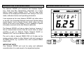
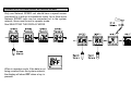
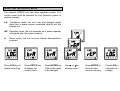
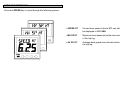
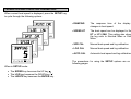
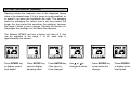
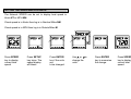
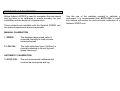
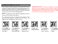
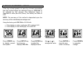
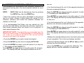
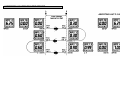
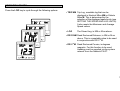
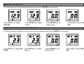
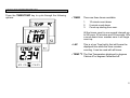
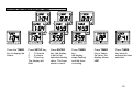
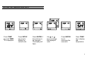
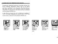
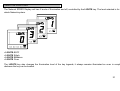
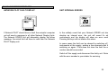
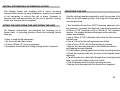
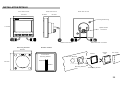
CONTENTS
GENERAL INTRODUCTION TO B&G NETWORK ................................................... 2
INSTRUMENTS NAVIGATIONAL AIDS .............................................................. 2
AUTOPILOTS COMMUNICATIONS ................................................................... 2
INTRODUCTION TO NETWORK SPEED ................................................................. 3
NETWORK SPEED DISPLAY UNIT .......................................................................... 3
EXAMPLES SYSTEMS USING NETWORK SPEED................................................. 4
SELECTING THE DISPLAY MODE........................................................................... 5
USING THE SPEED KEY........................................................................................... 6
CALIBRATION AND OPERATING PARAMETERS.................................................. 7
SETTING THE DISPLAY DAMPING.......................................................................... 8
SETTING THE SPEED AND LOG UNITS ................................................................. 9
SPEED AND LOG CALIBRATION .......................................................................... 10
SETTING THE TIMERS AND LAP TIMER .............................................................. 18
SETTING THE TEMPERATURE UNITS .................................................................. 19
CALIBRATING THE TEMPERATURE SENSOR .................................................... 20
USING THE LIGHTS KEY ......................................................................................... 21
NETWORK ALARMS ................................................................................................ 22
FAULT AND ERROR MESSAGES ........................................................................... 23
INSTALLATION........................................................................................................ 24
SITING THE UNIT SITING THE UNIT SITING THE UNIT ....................................... 24
MOUNTING THE UNIT ............................................................................................. 24
INSTALLATION DETAILS ....................................................................................... 25
SPECIFICATIONS .................................................................................................... 26
1 - MANUAL CALIBRATION - SPD CAL .............................................................. 11
2 - MANUAL CALIBRATION - LOG CAL .............................................................. 12
3 - AUTOMATIC CALIBRATION - AUTO CAL...................................................... 13
AUTOMATIC CALIBRATION PROCEDURE .......................................................... 14
USING THE LOG KEY .............................................................................................. 15
RESETTING THE TRIP LOG .................................................................................... 16
RESETTING THE DEAD RECKONED DISTANCE................................................... 16
USING THE TIMER/TEMP KEY ................................................................................ 17
1
GENERAL INTRODUCTION TO B&G NETWORK
The B&G Network range of instruments has been designed to
be used as individual units or connected together to form an
integrated navigational system. A single network cable is
used to carry data and power between units. The latest
technology and screened cables throughout the Network
System ensure the ultimate protection from interference
between units and other systems. All Network instruments
can be linked to Network PILOT, Network CHART, Network
GPS or Network LORAN receivers or via NMEA 0183 (v1.5)
to other navigational equipment.
INSTRUMENTS
NAVIGATIONAL AIDS
Network SPEED
Network DEPTH
Network QUAD
Network WIND
Network TACK
Network DATA
Network GPS
Network LORAN
Network NAV
Network CHART
AUTOPILOTS
COMMUNICATIONS
Network PILOT
Network VHF
2
INTRODUCTION TO NETWORK SPEED
NETWORK SPEED DISPLAY UNIT
The Network SPEED unit measures and displays Speed,
Log, Timer and Sea Temperature information on a large
back-lit Liquid Crystal Display (LCD). The five keys allow
selection of the displayed information and setting of the units
mode, calibration factors and operating parameters.
It can operate as the main Network SPEED unit either alone
or as part of an Integrated Network Instrument System taking
inputs directly from a Speed Sensor which plugs into the
socket at the rear of the display, or as a repeater of speed
information received via the two Network cable tails.
The Network SPEED unit has no alarm functions, however it
has an internal alarm buzzer that will sound when an alarm
condition is met on Network Depth, Network QUAD or
Network PILOT unit or to indicate a fault condition.
The unit is able to transmit NMEA 0183 (v1.5) data via the
system network cables to other Network units and connect to
an NMEA device e.g. a position fixer, with a special NMEA
output cable.
IMPORTANT NOTE
Your Network SPEED unit must be setup and calibrated
correctly before it is used as part of a navigational system.
3
EXAMPLES SYSTEMS USING NETWORK SPEED
Only one Network SPEED unit should have a speed sensor
connected to it and set to transducer mode. Up to three more
Network SPEED units can be connected on to the system
network, these must be set to repeater mode.
See SELECTING THE DISPLAY MODE.
When in repeater mode, if the data is not
being received from the system network,
the display will show OFF when a key is
pressed.
4
SELECTING THE DISPLAY MODE
The Network SPEED unit has three operating modes. The
correct mode must be selected for your Network system to
operate properly.
trA
Transducer mode, the unit uses and displays speed
data from a speed sensor connected directly into the
display unit.
rEP Repeater mode, the unit operates as a speed repeater
using data from the system network.
d
Demo mode, the unit runs an internal demonstration
program.
Press LOG key to
display stored log.
Press SETUP key
to display the
current mode.
Press ENTER key
if the mode needs
to be changed.
Use ¿ or À to
change mode.
Press ENTER to
store the new
mode in memory.
Press LOG to
complete the
change.
5
USING THE SPEED KEY
Press the SPEED key to cycle through the following options:
• SPEED KT
Current boat speed in Knots KT, can also
be displayed in MPH MH.
• MX SP KT
Maximum boat speed since the last reset
of the trip log.
• AV SP KT
Average boat speed since the last reset of
the trip log.
6
CALIBRATION AND OPERATING PARAMETERS
When current boat speed is displayed, press the SETUP key
to cycle through the following options:
• DAMPING
The response time of the display to
changes in boat speed.
• SPEED KT
The boat speed can be displayed in Knots
KT or MPH MH. This setting also changes
the log units to Nautical Miles or Statute
Miles.
• SPD CAL
Manual boat speed and log calibration
• LOG CAL
Manual boat speed and log calibration
• AUTO CAL
Automatic boat speed and log calibration
The procedures for using the SETUP options are on the
following pages.
When in SETUP mode:
• The SPEED key becomes the UP key ¿
• The LOG key becomes the DOWN key À
• The LIGHTS key becomes the ENTER key.
7
SETTING THE DISPLAY DAMPING
Damping allows the response time of the displayed speed
value to be slowed down if it is to jumpy in rough weather, or
to speed it up when the conditions are calm. The damping
works by averaging the values over a set time period; the
longer the time period the smoother the readings, however
the longer it takes to see a change. Similarly the shorter it is
the jumpier the readings, but the faster the response.
The Network SPEED unit has a factory set value of 5, this
can be adjusted in the range 1 to 64, each step is
approximately one second.
Press SPEED key
to display current
boat speed.
Press SETUP key
twice to display
damping value.
Press ENTER key
if the value is
to be changed.
Use ¿ or À to
change the value.
Press ENTER key
to memorise the
change.
Press SPEED key
to display current
boat speed.
8
SETTING THE SPEED AND LOG UNITS
The Network SPEED can be set to display boat speed in
Knots KT or MPH MH.
If boat speed is in Knots then log is in Nautical Miles NM.
If boat speed is in MPH then log is in Statute Miles M.
Press SPEED
key to display
current boat
speed.
Press SETUP
key twice. The
speed display
will blank.
Press ENTER
key if the units
are
to be changed.
Use ¿ or À to
change the
units.
Press ENTER
key to memorise
the change.
Press SPEED
key to display
current boat
speed.
9
SPEED AND LOG CALIBRATION
Before Network SPEED is used for navigation the boat speed
and log have to be calibrated to ensure accuracy for your
installation and the boats hull characteristics.
Use the one of the methods overleaf to calibrate your
instrument. It is recommended that AUTO CAL is used as
this method will ensure the most accurate calibration of your
Network SPEED unit.
Three methods are available with the Network SPEED unit,
two manual adjustments and one automatic:
MANUAL CALIBRATION
1 SPEED
The displayed boat speed value is
corrected manually to read a known
measured speed.
2 LOG CAL
The units calibration figure (Hz/Knot) is
manually adjusted to correct log and
speed inaccuracy.
AUTOMATIC CALIBRATION
3 AUTO CAL
The unit automatically calibrates and
corrects the boat speed and log.
10
1 - MANUAL CALIBRATION - SPD CAL
This procedure requires a reference boat speed with which to
compare the Network SPEED units displayed boat speed. For
example, another boat with an accurate calibrated log, or if
the top speed of the boat is known this value can be entered
during a sea trial to correct the displayed value.
IMPORTANT NOTE: This method of calibration must not be
carried out at boat speeds of LESS THAN 3 KNOTS as
inaccurate values can be entered into the unit's memory. If
the speed/log are not functioning correctly enter a calibration
value of 5.3 to 6.2 and then repeat the procedure.
NOTE: The accuracy of this method is dependant upon the
accuracy of the reference boat speed.
The example below shows a displayed boat speed of 7.25
knots, the boat speed is known to be 10.0 knots. The
displayed value is adjusted to read 10.0 knots.
Press SPEED key
to display current
boat speed.
Press SETUP key
three times to
display SPD CAL.
Press ENTER key
to adjust the
displayed value.
Use ¿ or À to
change the value.
Press ENTER to
store the new
value in memory.
Press SPEED key
to complete the
change.
11
2 - MANUAL CALIBRATION - LOG CAL
If the log or boat speed is in error by a known percentage
then this method allows the calibration figure or LOG CAL to
be adjusted by that amount. The calibration figure is
measured in Hertz per knot (Hz/kt), the factory set value is
6.25.
NOTE: The accuracy of this method is dependant upon the
accuracy of the calculated percentage error.
Using the factory set LOG CAL of 6.25 Hz/kt:
• If the display is under reading by 10% subtract 0.62
• If the display is over reading by 10% add 0.62
Press SPEED key
to display current
boat speed.
Press SETUP key
four times to
display LOG CAL.
Press ENTER key
to adjust the
displayed value.
Use ¿ or À to
change the value.
Press ENTER to
store the new
value in memory.
Press SPEED key
to complete
change.
12
3 - AUTOMATIC CALIBRATION - AUTO CAL
This procedure will automatically and accurately calibrate the
boat speed and log and is the recommended method for most
boats.
one run.
• Turn the boat around for run 2 in the opposite direction over
the same measured distance.
AUTO CAL can be aborted any time by pressing
the SETUP key, then the SPEED key.
Press the ENTER key when in line with marker B, to start run
2. The display will flash AUTO C 2.
• Select two markers that are easily identifiable on the ground
and on a chart, choose a place where the current is at a
minimum. Measure and record the distance between the
markers on the chart.
Press ENTER key again when in line with marker A, to freeze
run 2. The display will flash the accumulated distance so far
for two runs.
NOTE:
• It is recommended that three runs are carried out, this
accounts for tidal efforts, and improves accuracy. However a
time should selected when the current is at a minimum, ie
slack water between tides.
IMPORTANT NOTE: The total distance accumulated over the
three runs must exceed 0.16 Nautical Miles or 100 metres per
run. If this is not achieved the AUTO CAL will fail and the
procedure will have to be repeated.
• Press the SPEED key to select current boat speed.
• Turn the boat around for run 3 (final run) in the opposite
direction over the same measured distance.
Press the ENTER key when in line with marker A, to start run
3. The display will flash AUTO C 3.
Press ENTER key again when in line with marker B, to freeze
run 3. The display will flash the accumulated distance for three
runs.
• Multiply the recorded distance from the chart by the number
of runs completed. This is the true distance travelled.
• Press the SETUP key five times to display AUTO CAL.
• Adjust the flashing display with the ¿ and À keys until it is
the same as the true distance.
• Press the ENTER key when in line with marker A, to start run
1. The display will flash AUTO C 1.
Press ENTER key again when in line with marker B, to freeze
run 1. The display will flash, showing the distance so far for
• Press the ENTER key to complete the calibration. The
display will zero, and the calibration is memorised.
13
AUTOMATIC CALIBRATION PROCEDURE
ABORTING AUTO CAL
14
USING THE LOG KEY
Press the LOG key to cycle through the following options:
• TRIP NM Trip Log, resetable log that can be
displayed in Nautical Miles NM or Statute
Miles M. This is determined by the
selection of the displayed speed units (see
SETTING THE SPEED AND LOG UNITS).
It also resets the Maximum and Average
Speed values.
• LOG
The Stored Log, in NM or M as above.
• DR D NM Dead Reckoned Distance, in NM or M as
above. This is a resetable value to be used
in conjunction with DR C 0M.
• DR C 0M Dead Reckoned Course, in degrees
magnetic. For this function to be used
Heading must be supplied via the system
network from the Network PILOT.
15
RESETTING THE TRIP LOG
The Trip Log is reset to zero and starts again as soon as the ENTER key is pressed.
Press LOG key to display
TRIP NM.
Press SETUP key, Display
flashes.
Press ENTER key, the
display zeros.
Press LOG to display TRIP
NM.
RESETTING THE DEAD RECKONED DISTANCE
The Dead Reckoned Distance is reset to zero and starts again as soon as the ENTER key is pressed.
Press LOG key to display DR
D NM.
Press SETUP key, Display
flashes.
Press ENTERkey, the
display zeros.
Press LOG to display DR D
NM.
16
USING THE TIMER/TEMP KEY
Press the TIMER/TEMP key to cycle through the following
options:
• TIMER
There are three timers available:
1.
2.
3.
10 minute count-down
5 minute count-down
Count-up starting from zero.
All the timers count in one second intervals up
to 99 hours, 59 minutes and 59 seconds. When
a count-down timer reaches zero it will begin to
count up.
• LAP
This is a Lap Time facility that will freeze the
displayed time while the timer remains
counting. It can be used with all timers.
• TEMP 0C The Sea Temperature displayed in degrees
Celsius 0C or degrees Fahrenheit 0F.
17
SETTING THE TIMERS AND LAP TIMER
Press the TIMER
key to display the
timers.
Press SETUP key,
1
10 minute
2
5 minute
3
Count-up
The display will
flash.
Press ENTER
key, the display
is set to the
selected starting
value. The timer
starts to count.
Press TIMER
key,
the display
stops flashing
and the timer
is running.
Press TIMER
key to freeze
the timer, the
display shows
LAP.
Press TIMER
key twice to
resume the timer
selected.
18
SETTING THE TEMPERATURE UNITS
Press TEMP
key until TEMP
0
C is displayed.
Press SETUP
key once to
display the
current units.
Press ENTER if
the units are to
be changed.
The display will
flash.
Use ¿ or À
keys to change
the displayed
units.
Press ENTER
key to
memorise the
new units.
Press TEMP
key to display
sea
temperature
19
CALIBRATING THE TEMPERATURE SENSOR
Temperature calibration should only be carried out when the
built-in seawater temperature sensor (part of the speed
sensor) is considered to be inaccurate. The temperature of
the water will have to be measured with an accurate
temperature-sensing device; this value can then be entered
into the Network SPEED unit.
In the following example the unit is displaying a reading of
10.40C, the water temperature is known to be 11.40C. The
correct value is entered into the Network SPEED unit.
Press TEMP
key until
TEMP 0C is
displayed.
Press SETUP
key twice to
display TEMP
CAL.
Press ENTER
if to change.
The display
will flash.
Use ¿ or À
keys to
change the
displayed
units.
Press ENTER
key to
memorise the
new units.
Press TEMP
key to display
sea
temperature.
20
USING THE LIGHTS KEY
The Network SPEED Display unit has 3 levels of illumination and off, controlled by the LIGHTS key. The level selected is for the
whole Network system.
• LIGHTS 0 OFF
• LIGHTS 3 High
• LIGHTS 2 Medium
• LIGHTS 1 Low
The LIGHTS key also changes the illumination level of the key legends; it always remains illuminated so even in complete
darkness the key can be located.
21
NETWORK ALARMS
The Network SPEED unit has an internal buzzer that will
sound when an alarm condition is met on a Network unit that
has alarm functions ie. Network DEPTH and Network QUAD
for depth alarms and Network PILOT for Watch Alarm and Off
Course alarms. The unit will also display which alarm is
activated.
To silence the internal alarm and return the display to normal
operation press any of the five keys.
NETWORK PILOT ALARM DISPLAYS
DEPTH ALARM DISPLAY
The Watch Alarm is a count-down timer with is activated at
the end of the preset count-down period. The display
alternates between the messages above.
Depth alarms can be set for the following:
•
•
•
•
Shallow water
Deep water
Anchor Watch
Check your Network DEPTH or QUAD unit to see
which alarm is activated.
The Off Course alarm is activated when the boat deviates off
course by a preset amount. The display alternates between
the messages above.
22
FAULT AND ERROR MESSAGES
NETWORK PILOT FAULT DISPLAY
UNIT INTERNAL ERRORS
If Network PILOT should have a fault the autopilot computer
unit will send a message to all other Network Display Units.
The Network SPEED unit will alternately display the follow
message, the actual fault will have to read from the Network
PILOT Display unit.
In the unlikely event that your Network SPEED unit should
develop an internal error, the unit will sound it's alarm
continuously and the display will show an error number.
Pressing the keys will not silence this alarm.
In some cases the fault can be cleared by switching off the
instruments at the supply, waiting a few moments and then
switching on again. If this does not clear the fault the error
number should be recorded.
Switch off the supply and disconnect the faulty unit. Return it
with the error number to your dealer for servicing.
23
INSTALLATIONINSTALLATIONINSTALLATION
The display heads are supplied with a clip-in mounting
bracket which allows for easy installation, access from behind
is not necessary to secure the unit in place. However to
prevent theft and permanently fix the unit in position, locking
studs and thumb nuts are supplied.
SITING THE UNIT SITING THE UNIT SITING THE UNIT
All Network Instruments are designed for mounting on or
below deck. A mounting position should be selected where
they are:
• Easy to read by the helmsman
• On a smooth and flat surface
• At least 100mm (4") from a compass
• Accessible from behind for fitting locking studs if required.
MOUNTING THE UNIT
Use the cutting template supplied to mark the centres of the
holes for the self-tapping screw, the fixing stud holes and the
mounting bracket.
• The template allows 4mm (5/32") between adjacent units for
the suncover, increase this distance if required to maximum
of 60mm (2 3/8") between units or 180mm (3 1/8") between
centres. For greater distances between units extension
cables are available.
• Use a 70mm (2 3/4") diameter hole-cutter for the mounting
bracket hole.
• Use a 2.9mm for the self-tapping screw holes.
• Use a 5mm (3/32") drill for the locking stud holes.
• Secure the mounting bracket to the bulkhead with the
self-tapping screws supplied
• Fit the rubber sealing gasket around the mounting bracket.
• Screw the locking studs into the back of the display head (if
required).
• Carefully pass the cable tails through the mounting bracket
hole, connect the cables to the main units.
• Clip the display head into the mounting bracket.
• Secure the instrument with the thumb nuts supplied.
24
INSTALLATION DETAILS
Front View of Unit
110.0mm
Side View of Unit
25.0m m
Rear View of Unit
65.0m m
Network SPEED
Locking Stud Fixing
110.0m m
Speed Sensor
Connector
SPEED
LO G
TIMER
TEMP
SETUP
LIG HTS
ENTER
Network Connector
Mounting Bracket
Network/Power Connector
Rubber Gasket
82.0m m
fit around the
m ounting bracket
82.0m m
Gasket
Display
Unit
Sun Cover
70.0m m Dia Hole
Bulkhead
Gasket
Mounting Bracket
Self-tapping Screws
25
SPECIFICATIONS
PHYSICAL PARAMETERS
ELECTRICAL
Construction
Window
Display
Power Supply
Operating Current
Protection
Dimensions
Weight
High impact ABS plastic
Acrylic
Back-lit Liquid Crystal Display:
Large Digits: 28.6mm 1.12"
Small Digits: 11.5mm 0.45"
110 x 110 x 25.4mm 4 x 4 x 1"
Requires 65mm 2.6" depth behind
bulkhead for display barrel
0.3 kg 0.66lbs
ENVIRONMENTAL
Operating Temp
Storage Temp
Humidity
Sealing
-10 to +550C @ 93%RH
+14 to +1310F @ 93%RH
-25 to +700C @ 95%RH
-13 to +1580F @ 93%RH
Up to 95%RH
Fully sealed front, suitable for bulkhead
cockpit mounting. Vented barrel to prevent
condensation.
12V DC nominal (10 to 16V)
40mA typical, 100mA illuminated
Connect via external 5A fuse or
circuit breaker.
CABLES AND CONNECTIONS
Connection to adjacent units is via cable tails fitted with either
a plug or a socket. Extension cables are available from your
dealer. The cable tails carry power and NMEA data between
units.
ALARM
Internal audible alarm
NMEA OUTPUT SENTENCES
$IIHDM
$IIVHW
$IIDBT
$IIVWR
$IIMTW
Heading
Speed and Heading
Depth
Apparent wind angle and speed
Sea temperature
26