1
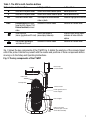
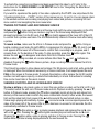
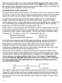
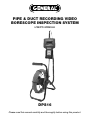
PIPE & DUCT RECORDING VIDEO BORESCOPE INSPECTION SYSTEM USER’S MANUAL DPS16 Please read this manual carefully and thoroughly before using this product. TABLE OF CONTENTS Introduction . . . . . . . . . . . . . . . . . . . . . . . . . . . . . . . . . . . 3 Key Features . . . . . . . . . . . . . . . . . . . . . . . . . . . . . . . . . . 4 Safety Instructions . . . . . . . . . . . . . . . . . . . . . . . . . . . . . 4 What’s in the Case. . . . . . . . . . . . . . . . . . . . . . . . . . . . . . 5 Product Overview . . . . . . . . . . . . . . . . . . . . . . . . . . . 6 – 8 Setup Instructions . . . . . . . . . . . . . . . . . . . . . . . . . . . 8 – 9 Attach Probe to Console . . . . . . . . . . . . . . . . . . . . . 8 Charge Console Battery . . . . . . . . . . . . . . . . . . 8 – 9 Insert SD Card . . . . . . . . . . . . . . . . . . . . . . . . . . . . . 9 Operating Instructions – H16 . . . . . . . . . . . . . . . . . 9 – 15 Viewing Live Video on the Console. . . . . . . . . 9 – 10 Viewing Live Video on a TV Monitor . . . . . . . 10 – 11 Taking Pictures and Recording Videos . . . . . . . . . 11 Viewing Photos and Playing Back Videos . . 11 – 12 Accessing SD Card Content . . . . . . . . . . . . . 12 – 13 Navigating the Main Menu. . . . . . . . . . . . . . . 13 – 15 Operating Instructions - P16PIP . . . . . . . . . . . . . . 15 – 16 Attaching an Accessory. . . . . . . . . . . . . . . . . . . . . 15 Specifications . . . . . . . . . . . . . . . . . . . . . . . . . . . . 17 – 18 Operating, Maintenance & Troubleshooting Tips - H16. . . . . . . . . . . . . . . . . . . . . . 19 Operating & Maintenance Tips - P16PIP . . . . . . . . . . . 20 Compatible Probes . . . . . . . . . . . . . . . . . . . . . . . . . . . . 21 Warranty Information. . . . . . . . . . . . . . . . . . . . . . . . . . . 22 Return for Repair Policy . . . . . . . . . . . . . . . . . . . . . . . . 22 2 INTRODUCTION Thank you for purchasing General Tools & Instruments’ (General’s) DPS16 Pipe & Duct Recording Video Borescope Inspection System. Please read this user’s manual carefully and thoroughly before using the instrument. The DPS16 has two components: the H16 Handheld Recording Video Borescope Console and the P16PIP Pipe & Duct Inspection Probe & Reel Set. The H16 is the console of General’s top-of-theline video borescope inspection systems: the DCS1600, DCS1600ART and DPS16. A thumbwheel on the left side of the H16 allows you to adjust the brightness of the LEDs illuminating the camera at the end of any probe attached to it. The P16PIP probe and reel set included in the DPS16 system is tailored for inspecting water and sewer pipes carrying running water, as well as HVAC ducts. The H16 also can serve as the console of a general-purpose recording video borescope system with the addition of a compatible probe. See p. 21 for a list of probes compatible with the H16. The H16 has three operating modes: Preview, Playback and Menu: • In Preview mode, video framed by the camera’s field of view is displayed in real time on the console’s LCD. The H16 automatically enters this mode when powered on. A front-panel button allows you to enlarge (zoom in on) a target by 50% (a zoom level of 1.5X). The same button allows you to “mirror” video, making it possible to read serial numbers seen and “reversed” by an attached probe with a mirrored viewing tip. In Preview mode, real-time video also can be exported through an included video cable to any NTSCor PAL-format TV monitor with an RCA input jack. Operating in Preview mode, the H16 also allows you to record inspection videos (at 320 x 240 pixel resolution) and photos (at 640 x 480 pixel resolution) on an included SD memory card by pressing icon-labeled buttons on the console’s front panel. The remaining frontpanel buttons enable access to Playback and Menu modes. • In Playback mode, you can browse the SD card for saved video and picture files and view the media on the console’s LCD or a larger TV monitor. Video clips and photos also can be viewed on a PC in either of two ways: 1) by removing the SD card and plugging it into the computer directly or through a card reader; or 2) by using a supplied cable to connect the H16 to the PC through one of its USB ports. Because videos are saved as .asf files and photos as .jpg files, applications found on most PCs (Microsoft Windows Media Player and Microsoft Office Picture Manager) can open the files. The 2GB SD memory card included in the DPS16 case can store at least 5 hours of video, recorded at an average of 6 Mbytes/minute, in addition to hundreds of photos. • In Menu mode, you use familiar scrolling motions and responses to dialog boxes to navigate a main menu with six submenus. When selected, submenu items execute “housekeeping” functions such as deleting files, setting the date and time, enabling or disabling date and time stamps, choosing any of 14 languages for display indications, selecting a Video out format and adjusting the console’s Auto Power Off trigger. One of the submenus has a subsubmenu that allows you to adjust four attributes (brightness, contrast, hue and saturation) of video viewed on the console or an external monitor. 3 KEY FEATURES • Ideal for examining the interior of water pipes, sewer pipes, and HVAC ducts. Especially tailored for 2, 4 and 6 in. I.D. pipes by included probe centering accessories • 72 ft. (22m) long probe with 1.1 in. (28mm) diameter camera head • Eight super-bright white LEDs give probe 640 x 480 pixel (VGA) resolution; superior optics yield excellent depth of field of 0.4 in. (10mm) to infinity • Probe is water-tight to IP68 standard (depth of 33 ft./10m) and flexible enough to make two or more (depending on conditions inside the pipe) 90° bends in a 1.6 in. (40mm) I.D. pipe • Stainless steel camera head is immune to bathroom toilet cleaner, pipe and drain cleaning chemicals, gasoline, brake/transmission fluid and machine oil • Steel probe reel is sturdy and dust-tight to IP6X standard, works vertically or horizontally, and has bracket for H16 (DCS1600) console • 3.5 in. diagonal color LCD for viewing probe video in real time and saved video and pictures later • Compatible with dozens of high-performance camera-tipped probes from General (see p. 21) • Thumbwheel for adjusting brightness of camera lighting • Familiar menu-driven user interface for viewing and recording videos and photos on standard SD memory card (2GB card included) and playing back media on console, TV or PC • Rechargeable battery with 4-hour capacity • 1-year limited warranty SAFETY INSTRUCTIONS CAUTION! Never insert any probe attached to the H16 into any structure or space known or suspected to contain live electric wiring • The DPS16 and H16 are intended for industrial applications only. Do not use a compatible probe for human or any other biological inspections. • Never insert an attached probe into any flammable gas or liquid (including fuels in an oil, gasoline or diesel tank) • Do not disassemble the H16 console. Doing so creates a potentially fatal electrical hazard (and voids the warranty as well). 4 WHAT’S IN THE CASE The DPS16 comes in a custom hard plastic protective carrying case. Inside the case are: • The H16 console. The console integrates an LCD monitor, a connector for a highperformance camera-tipped probe from General, and front-panel controls for controlling the camera’s lights, adjusting system parameters, and recording and playing back videos and photos captured by an attached probe. • The P16PIP Pipe & Duct Inspection Probe & Reel Set • One spherical metal ring for centering the probe in 2 in. I.D. pipes • One brush set for centering the probe in 4 in. I.D. pipes • One brush set for centering the probe in 6 in. I.D. pipes • A 5/64-in. Allen wrench for attaching the 2 in. probe centering ring • A plastic bag containing five spare 5/64-in. Allen screws • A 2GB SD memory card for the H16 • An AC adapter/battery charger for a 110/220VAC supply. The adapter has a 5.5VDC, centerpositive output plug. • A video cable for connecting the H16 to a TV monitor. The cable has RCA plugs at one end and a mini-stereo plug at the other end. • A USB cable with a mini-USB plug on one end and a full-size USB plug on the other end. It can be used to display the contents of the SD card on a computer directly, without removing the card from the console. • A soft cloth, a bottle of liquid, and cotton swabs for cleaning the console • A package of desiccant • This user’s manual 5 PRODUCT OVERVIEW Fig. 1 shows the names and locations of all of the controls, ports and jacks of the H16. Table 1 details how the function of each front-panel changes with the console’s operating mode. Familiarize yourself with the labels, positions and functions of all buttons and connectors before moving on to the Setup Instructions and Operating Instructions. 14 8 9 11 10 4 5 12 7 6 15 2 1 3 LEFT SIDE 13 FRONT BACK RIGHT SIDE Fig. 1. The controls, ports and jacks of the H16 1 2 3 4 5 6 7 8 9 6 Start/Stop Video Recording Button Snapshot Button Power On/Off Button Previous Video/Photo Button ▼ Next Video/Photo Button OK OK Button ESC Escape/Zoom/Mirror Button SD Card Socket TV Out Jack 10 11 12 13 14 15 AC Adapter Jack Mini-USB Jack Brightness Adjustment Thumbwheel Hanger Hole Probe Connector Reset Button Table 1. The H16’s multi-function buttons Button Label In Preview Mode In Playback Mode In Menu Mode ▲ Switches to Playback mode Selects next-oldest video or photo Moves up one line ▼ Switches to Playback mode Selects next-newest video or photo Moves down one line OK Switches to Menu mode Offers option to delete selected video or photo Executes highlighted command ESC Presssed briefly, enlarges target by 50% (zooms 1.5X) Pressed and held, mirrors video Switches to Preview mode Switches to Preview mode Takes a picture Recalls next photo or (stores .jpg photo on SD card) pauses/plays video clip Displays repair data or opens submenu of video attribute options Starts/stops recording an .asf video on SD card Switches to Preview mode Switches to Preview mode Fig. 2 shows the key components of the P16PIP. Fig. 3 details the anatomy of the camera-tipped end of the probe. Familiarize yourself with the names and positions of these components before moving on to the Setup and Operating Instructions. Fig. 2. The key components of the P16PIP Handle Borescope console holder Reel frame Coiled probe Camera head Probe guide/camera head stopper Reel stopper Probe connector (to borescope console or handle/controller) 7 Camera head Accessory mounting ring Fig. 3. Structures near the camera-tipped end of the probe Rubber probe cover Metal coil spring sleeve Joint ball Probe SETUP INSTRUCTIONS ATTACH PROBE TO CONSOLE Attach the P16PIP to the H16 by 1) inserting the H16 into the bracket at the top of the P16PIP and 2) plugging the P16PIP’s probe connector (see bottom of Fig. 2) into the connector at the top of the console (Fig. 1, Callout 14). The connectors mate in only one way, when the two red dots— one on the console’s connector and the other under the collar at the end of the probe—are aligned. After you have lined up the dots, push the two connectors together so the alignment keys on opposite sides of the probe’s connector slide over the flats of the console’s connector. Slide the collar on the probe’s connector forward and tighten the collar by turning it clockwise. You can now remove the protective rubber cap from the camera-tipped end of the probe. It is good practice to replace the cap whenever the probe will not be used for a while. Now is also the time to peel away the plastic film that protects the console’s LCD. To disconnect the probe from the console, turn the collar counterclockwise and pull the probe straight out and away. CHARGE CONSOLE BATTERY To power on for the first time, plug one end of the supplied AC adapter/battery charger into a wall socket. Then swing the black rubber protective flap away from the right side of the H16 to expose the AC adapter jack (Fig. 1, Callout 10). Insert the cylindrical plug at the end of the adapter/charger cable into the AC adapter jack. This will begin charging the console’s battery. 8 Push the button and hold it for at least five seconds. The LCD will illuminate and briefly show the word “CAMERA” on the left and a battery icon on the right (both in green), superimposed on video being captured in real time by the camera at the end of the probe. Use the thumbwheel on the left side of the console (Fig. 1, Callout 12) to adjust the intensity of the camera’s lighting. In a brightly lit room, moving the thumbwheel has a big effect on the brightness of the LEDs at the tip of the probe, but a much smaller effect on the brightness of video on the screen. The on-screen impact of changing brightness is more pronounced in dark environments. To turn off the H16, push the button and hold it for at least five seconds. It will take several hours to fully charge the H16’s Lithium-ion battery the first time. You cannot replace the battery, which can only be replaced by General-authorized service personnel. Do not open the case in an attempt to change the battery yourself. Doing so creates a potentially fatal electrical hazard (and voids the warranty as well) with the AC adapter plugged in. With proper care (charging the battery often, and never allowing it to completely discharge), you can expect the H16’s battery to last four or five years. A fully charged battery should power at least four hours of operation. INSERT SD CARD This step enables the H16 to store video clips and photos. Remove the supplied 2GB SD memory card from its packaging. Discard the packaging, but save the plastic storage case. Push the SD card into the socket on the right side of the console (Fig. 1, Callout 8). Be sure the card’s gold contacts are facing front and enter the socket first. Push in the card until you feel it spring back and you hear a click. To remove the card later, push it in gently until you hear a click and the card pops out far enough for your fingers to grab. OPERATING INSTRUCTIONS – H16 VIEWING LIVE VIDEO ON THE CONSOLE While the battery charges, General recommends becoming familiar with the H16’s controls, indicators and menu options before taking the unit out into the field. The H16 operates the same way whether powered by its battery or the AC adapter. To begin, power off the unit by pressing and holding the button. Then press and hold the button again to power the console back on. Each time the console is powered on, the screen shown below will appear briefly. The text, bars and battery icon will appear in green, superimposed on live video captured by the camera probe. Together, the number of bars and the color of the icon represent the H16’s two “vital signs”—battery charge and available memory capacity. The number of filled-in bars at the bottom of the screen reflects the amount of data currently stored on the SD card. A full card would produce four green bars. The greener the icon above the bars, the higher the current level of battery charge. A completely green icon would indicate a fully charged battery. 9 Next, get used to manipulating your probe. Instructions for using the P16PIP probe and reel can be found beginning on p. 15 of this manual. If you plan to buy and attach one of General's conventional (non-pipe & duct) borescope probes to the H16, the following instructions for manipulating flexible-obedient and soft metal probes apply to you. Typically, users insert a probe into an orifice (a hole in a wall or an engine’s cylinder, for example) or into an inaccessible or hazardous area (the back or an equipment rack or an engine compartment, for example) to view components or environments that would otherwise be invisible. In practice, professionals usually insert flexible-obedient probes head-on into an orifice or area as a first step. They then pull the probe out and adjust its bend one or more times until the camera in the tip is pointing directly at the target or area of interest. With the probe inserted, you can twirl it until video appears right-side up, but in many cases you cannot change the probe’s angle of approach very much. Soft metal probes, which are more flexible but do not retain their shape, require different inspection strategies and tactics to suit the application and environment. Finally, note the dual function of the ESC button in Preview mode: • Press the ESC button briefly and targets will be enlarged by 50% as the camera’s field of view is reduced by that amount. A red plus sign (+) will appear on-screen and remain there after the available memory capacity bars and the battery charge icon make a brief appearance. • Press and hold the ESC button and video will be mirrored horizontally, as shown in the two photos below. The effect makes it possible to read text or serial numbers“reversed” by an attached probe with a mirrored viewing tip—by undoing the reversal. A red “M” will appear on-screen to indicate that video is being mirrored. You can mirror and zoom videos at the same time by pressing the ESC button briefly, and then pressing and holding the button. VIEWING LIVE VIDEO ON A TV MONITOR The H16 comes with a video cable for connecting the console to a TV or TV monitor that uses either the NTSC or PAL analog broadcast standard. By making the connection, you can view live video (or saved videos and pictures) on a screen larger than the H16’s. To implement the connection in hardware, insert the stereo mini-plug of the provided cable into the TV out jack of the H16 (Fig. 1, Callout 9). Then insert the yellow RCA plug at the other end of the cable into the Video in jack of your TV or TV monitor. Be sure to set the TV input to external video. Real-time videos shown on an external monitor can be enlarged by pressing the ESC button. But videos cannot be mirrored, as they can when viewed on the H16’s LCD. 10 To activate the connection in software and begin exporting H16 video to a TV, refer to the instructions for the VIDEO FORMAT and AV OUTPUT lines in the “Navigating the Main Menu” section of this manual. If you want to experience the quality of live video captured by the P16PIP now, skip ahead to the “Operating Instructions – P16PIP” section of this manual on pp. 15 and 16. You can always return to the unread sections on recording and playing back videos and pictures, accessing SD card menu content, and navigating the main menu later. TAKING PICTURES AND RECORDING VIDEOS To take a picture, make sure the H16 is in Preview mode (with live video appearing on the LCD) and press the button. Doing so creates a .jpg file of the frame being displayed at that moment and stores it on the SD card. A red icon briefly appears at the lower left of the LCD to confirm that a picture was taken. The H16 automatically returns to Preview mode after taking a picture. To record a video, make sure the H16 is in Preview mode and press the button. Doing so begins creating an.asf video file (with MPEG-4 compression) for storage on the SD card. A red icon appears at the lower left of the screen to confirm that a recording is in progress, and it remains there for the duration of the video. To stop recording, press the button again. This makes the red icon disappear and returns the H16 to Preview mode. While a video is being recorded, all console buttons other than the and buttons are disabled. Pressing the button takes a picture, stops recording video and returns the H16 to Preview mode. The H16 will be unable to store videos and pictures if its SD memory card is full, write-protected or damaged. When the instrument senses any of these conditions, it will superimpose the word FULL on the screen in Preview mode. To remedy the situation, either replace the full SD card by another card with spare capacity, or delete files individually or in bulk. Instructions for deleting files can be found later in this user’s manual. VIEWING PHOTOS AND PLAYING BACK VIDEOS To view a picture or play back a video (or more than one picture or video) on the H16’s LCD or a TV monitor, switch the unit out of Preview mode and into Playback mode by pressing the ▲ or ▼ button. In Playback mode, pressing the ▼ button repeatedly recalls all photos and videos from memory in the reverse order in which they were created and stored (in other words, the newest first and the oldest last). Each press of the ▲ button selects the next oldest picture or video. Videos begin playing automatically. A green icon and a red icon are superimposed on the video at the lower left of the screen. After a photo has been on-screen for 60 seconds, the H16 automatically switches to Preview mode. Pressing the button while a video is playing pauses playback and replaces the red icon with a red icon. Pressing the button again resumes play and restores the red icon. Pressing the button while a video is playing switches to Preview mode. Pressing the button while a picture is being displayed selects the next newest file. 11 While each photo and video is on-screen, pressing the OK button gives you the option to delete its file. Pressing the button calls up a dialog box with the word DELETE above the flashing word NO. Pressing the ▲ or ▼ button changes the flashing word to YES. When the correct answer (for you) appears, press the OK button to choose that action. ACCESSING SD CARD CONTENT Photos and videos stored on the SD card also can be viewed on a PC. If your computer has an SD card slot, you can remove the card from the H16 and plug it directly into a PC. If your PC does not have an SD card slot, you can purchase a USB SD card reader (Part No. SDRD1) from General. If you choose to remove the SD card from the console and plug it into a PC, either directly or through a card reader, remember to eject the card from the PC once you are done viewing (and/or copying) the files it contains. Depending on your PC’s startup settings, your computer may fail to restart following its next shutdown if the SD card remains inserted. The PC’s operating system may try to reboot from the SD card and be unable to do so. Another option for viewing inspection video and photos on a PC is to use the supplied USB cable to link to the computer. The first time you connect the H16 to a computer in this way, you will be prompted that “Driver Software is Being Installed.” The final Driver Software Installation dialog box advises that “Your device is ready to use” and specifies the following: USB Mass Storage Device ✓Ready to use Sunplus Sunplus SPCA436 USB Device ✓Ready to use As the notifications make clear, with the USB cable connected your computer will treat the SD card in the H16 as an external disk drive named Sunplus SPCA436. While the connection is made, however, you cannot view real-time videos on the H16’s LCD, a TV monitor, or your computer. You cannot even record videos or take photos and store them on the SD card. Connecting the cable powers off the H16. The only benefit of using the USB cable is that you do not have to remove the SD card to view its contents on a PC. Details of the SD’s file structure are worth mentioning because assigned file names contain useful information. The figure below illustrates the hierarchy. It shows that the SD card contains one folder named “DCIM” and one subfolder named “100MEDIA”. The 100MEDIA folder contains all stored photo and video files, identified by their.JPG and .ASF extensions. You should not rename the DCIM and 100MEDIA folders while the SD card is inside your PC or connected to it. If you rename either folder, the H16 will fail to recognize the SD card the next time you plug it into the console. The 8-digit file names identify the date and time when the file was created. The first two digits represent the month and day, and the last six digits represent the hour, minute and second. For example, the upper file name shown above identifies a photo file that was created on January 1 at 06:14:23 a.m. The lower file name identifies a video file that was created on the same day at 06:14:35 a.m. 12 The H16’s file-naming convention uses the letters A through C to represent the months October through December, and the letters A through V to represent days of the month from 10 through 31. For example, a file created on October 11 would begin with the letters AB (A for 10 and B for 11). As another example, a file created on November 30 would begin with the letters BU (B for 11 and U for 30. Finally, the file-naming convention uses military (24-hour) time. For example, a name with the last six digits 142531 would indicate a file created at 02:25:31 p.m. NAVIGATING THE MAIN MENU The main menu of the H16 provides access to the following housekeeping and operational functions: • Bulk file erasure • Video exporting • Setting the date and time • Choosing a display language • Selecting a TV format and adjusting video atrtributes • Enabling/disabling and adjusting the Auto Power Off function Menu mode has a hierarchical structure and uses prompts and dialog boxes familiar to anyone who has used an Automated Teller Machine (ATM). The only constraint on using the menu is your own response speed. If no selection is made within 10 seconds following Menu mode startup, the console will automatically revert to Preview mode. The same time constraint applies to selections within submenus. If you do not respond to a prompt (indicated by a flashing word or line of text) within 10 seconds, the H16MAIN will switch MENUback to Preview mode—its default operating state. MAIN MENU To access the main menu, press the OK button to enter Menu mode. DELETE ALL FILES Doing so brings up the screen shown at right. AV OUTPUT DATE/TIME SETUP To navigate the main menu, use the ▲ and ▼ buttons to move up LANGUAGE and down until the parameter you wish to change is highlighted and VIDEO FORMAT AUTO POWER OFF flashing in green. Then push the OK button to select it and call up its submenu. The DELETE ALL FILES line gives you two options (yes and no) that can be selected using the ▲ and ▼ buttons. The sequence is similar to the previously described procedure for deleting an individual photo or video. The AV OUTPUT line allows you to send the real-time video stream shown on the display unit out through the unit’s TV out jack to an NTSC or PAL TV monitor. The H16’s display will turn black until you select this option again. Before activating this function, make the physical connection described in the “Viewing Live Video on a TV Monitor” section. The DATE/TIME SETUP line allows you to set the H16’s calendar and clock. Doing so is necessary only if you wish to keep track of your photo and video files by date and time. When DATE/TIME SETUP is selected, the screen that appears has the year flashing in green. To 13 increase the value, press the button. To decrease the value, press the button. Once you have set the year, advance to the next field—the month—by pressing the ▼ button. Set the month as you did the year, by using the ▲ and ▼ buttons to increase or decrease the value by one unit per button press. Repeat this process until all six date and time components have been set. To back up from any field to the previous field, press the ▲ button. The bottom line of the DATE/TIME SETUP screen also allows you to choose whether or not to superimpose the date and time on the display in Preview mode. The default condition is “display off”, meaning the date and time are not displayed. To always superimpose the date and time, navigate down to the bottom line until the word OFF below the word DISPLAY is flashing in green. Then push either the or button to change the flashing word to ON. Finally, press the OK button to save the setting. The LANGUAGE line of the main menu allows you to view the main menu, as well as the DELETE screens for individual photos and videos, in any of ten languages (English, Spanish, Italian, French, German, Portuguese, Traditional Chinese, Simpified Chinese, Japanese, Danish, Dutch, Polish, Russian and Bulgarian). Use the ▲ and ▼ buttons to navigate to the language you wish to use and then push the OK button. The VIDEO FORMAT line enables you to choose either NTSC or PAL formatting of the videos you export to a TV monitor. Press either the ▲ and ▼ button to make your choice and then push the OK button to save the setting. Pressing the button with either NTSC or PAL flashing in green on the VIDEO FORMAT submenu opens a sub-submenu with the following lines: Brightness, Contrast, Hue and Saturation. You can use this submenu to change any of those four video attributes from the default factory settings. The default factory settings are: 00 for Brightness, 40 for Contrast, 00 for Hue, and 50 for Saturation. To change the value of any attribute, navigate to its line and press the OK button when its name begins flashing in green. The screen will then go dark except for the name of the attribute at the top. To increment the value from the factory default value, press the ▼ button (the opposite of what you’d expect). To decrement the value, press the ▲ button (again, the opposite of what you’d expect). There are 256 options for the value of each video attribute, and the attributes are identified and ordered by hexadecimal (base 16) numbers. For example, pressing the ▼ button to increment the value 09 produces 0A (the number 10 in base 16 notation); further increments yield 0B through 0F (the numbers 11 through 15). Incrementing 0F produces the value 10 (the number 16 in hexadecimal notation). Similarly, incrementing 19 produces the value 1A; further increments yield 1B through 1F. Incrementing 9F produces A0, further increments produce A1 through A9, and further increments produce AA through AF. Incrementing AF produces BA, and so on, through FF (the number 255 in hexadecimal notation). Incrementing FF completes the cycle, producing a value of 00. The AUTO POWER OFF line of the main menu is not visible on the screen that first appears after you press the OK button to put the H16 into Menu mode. To show the line, scroll down past the VIDEO FORMAT line. When the AUTO POWER OFF line appears, flashing in green, press the OK button. 14 By default, the AUTO POWER OFF function of the H16 is disabled. To enable it, and to choose how quickly to power off the instrument following a period of inactivity, navigate to one of the four options (5, 10, 15 or 30 minutes) and press the OK button. To re-disable the function later, enter Menu mode, scroll down to the AUTO POWER OFF line, press the OK button, select DISABLE and press the OK button again to save the setting. OPERATING INSTRUCTIONS - P16PIP Before inspecting a pipe, determine its inner diameter. Then determine whether that diameter matches the diameter of any of the three included probe-centering accessories: 2, 4 or 6 inches. If your pipe is one of these three sizes, attaching the correct accessory will keep the camera head in the center of the pipe as you push the probe forward. A centered probe will be easier to push forward and produce higher-quality videos and photos as well. If the inner diameter of your pipe is not 2, 4 or 6 in., you can still use the probe to good effect without the benefit of a probe-centering accessory. You may have to exert a bit more effort to keep the camera head from getting hung up on the pipe’s sidewalls as you push the probe forward. That is more likely if you use the probe to inspect large pipes or rectangular ducts. In such situations, friction will often cause the camera head to “tuck under” the probe as you push it forward, producing a rear-facing dynamic view of the pipe’s interior. When you begin to reel in the probe, however, the metal coil spring sleeve (see Fig. 3) will free the camera head and point it forward. Videos and photos captured during this “return” trip can be just as valuable as forwardfacing evidence. ATTACHING AN ACCESSORY Before attaching any of the three probe-centering accessories to the probe, “play out” a few feet of the probe from the reel. To do so, first “unlock” the reel by separating (opening) the Velcro closure called the Reel stopper (see Fig. 2 and upper figure at right). Once the reel is free to move, grab the probe below the camera head and begin pulling it horizontally, rather than vertically, as shown at lower right. Extract just enough probe for the Joint ball to pass the Probe guide/camera head stopper (see Fig. 2). Then— if this is the first use of the P16PIP or its first use in months—pull and push the end of the probe back and forth a few times (see left figure at the top of the next page) to reduce any friction binding the reel’s stationary and moving parts. ✓ 15 Once you have played out a few feet of probe, lock the reel by fastening the Velcro closure around the reel frame, as shown below at right. You can now attach the 2 in. spherical ring, the 4 in. brush set or the 6 in. brush set to the probe tip. To attach the ring, slide its slightly larger open end over the camera head (it fits only one way) until the head protrudes about 1/8 in. past the ring’s other opening. In this position, the ring’s Allen set screw will line up with the Accessory mounting ring of the camera head (see Fig. 3). Secure the ring to the head by using the included Allen wrench to tighten the screw, as shown at right. To attach either probe-centering brush set, identify the end with three set screws. Passing the camera head through the other end first, slide the probe through the brush set until the camera head protrudes 1/8 in. past the end with the set screws (see figures below). In this position, the three set screws will line up with the head’s Accessory mounting ring. Secure the brush set to the head by hand-tightening the screws. Screw holes 16 SPECIFICATIONS CONSOLE Display Type Color TFT LCD Display Size 3.5 in (89mm) diagonal Display Resolution 320 by 240 pixels (QVGA) Video Recording Resolution 320 x 240 pixels (QVGA) Video File Format .asf Photo Recording Resolution 640 x 480 pixels (VGA) Photo File Format .jpg Video Out Formats NTSC, PAL Video Frame Rate 30 frames per second (fps) Compression Format Compatible with MPEG4 Signal-to-Noise Ratio 42dB or greater Recording Medium Standard-size SD card Interfaces AV Out, USB 2.0 Languages English, Spanish, Italian, French, German, Portuguese, Traditional Chinese, Simpified Chinese, Japanese, Danish, Dutch, Polish, Russian, Bulgarian Power Source Rechargeable 3.7V Li-ion battery Power Consumption 1.8A @ 5.5VDC Operating Temperature -4° to 140°F (-20° to 60°C) Storage Temperature -4° to 140°F (-20° to 60°C) Recharge Temperature 32° to 104°F (0° to 40°C) Console Dimensions 8.5 x 4.7x 1.4 in. (215 x 120 x 36mm) Console Weight 13.4 oz (380g) 17 SPECIFICATIONS PROBE & CAMERA Camera Head Diameter 1.1 in. (28mm) Probe Diameter 0.23 in. (6mm) Probe Length 72 ft. (22m) Probe Material Fiberglass Camera Light Source 8 white LEDs Camera Depth of Field 0.4 in. (10mm) to infinity Camera Field of View 150.8° (diagonal) Waterproof Depth (IP68) 50 ft. (10m) Operating Temperature 14° to 158°F (-10° to 70°C) Weight 4.9 lb. (2.2kg) REEL Frame Diameter 11.8 in. (300mm) Dust and Water Resistance To IP65 standard Operating Temperature 14° to 158°F (-10° to 70°C) Weight 6.6 lb. (3kg) 18 OPERATING, MAINTENANCE & TROUBLESHOOTING TIPS – H16 • Never remove the SD card while taking a picture or recording a video. Doing so may damage the card and erase or corrupt the photo or video. • If the LCD remains or goes dark, the first two things to check are the integrity of the console’s connection to the probe and the charge of the console’s battery. The reason for the absence of video also could be that you have forgotten to remove the red rubber cap protecting the probe tip. • If live video begins to look spotty, streaky or intermittent, the likely reason is an undercharged battery. Plug in the AC adapter/battery charger immediately. • Video recording requires an SD card with a fast writing speed. For maximum video quality, General recommends SD cards with a writing speed of 80X or higher. • If the console “freezes” (pushing buttons has no effect) like a computer, straighten out a paper clip and use one end to press the Reset button on the back of the console (Fig. 1, Callout 15). • Avoid using corrosive liquids such as alcohol to clean either the LCD or the probe. To clean the camera lens and LEDs, use a cotton swab and a small amount of cleaning solution. To clean the LCD, use the provided cloth, cotton swabs and liquid. To clean the housing of the console, use a soft, dry cloth. • Operate and store the H16 only in a cool (under 140ºF or 60ºC), dry, well-ventilated place. Avoid exposing the unit to sunlight for long periods of time. • To avoid damaging the console, use only compatible probes and accessories. 19 OPERATING & MAINTENANCE TIPS - P16PIP The reel operates equally well in a horizontal or vertical position. The bracket for the H16 (DCS1600) borescope console at the top of the P16PIP has a flexibleobedient stem that allows the console’s screen to be angled to a comfortable viewing position. DO NOT BEND this stem at an angle greater than 90° (see figures immediately below). Before attempting to wind the probe back onto the reel, remember to “unlock” the reel by undoing the Reel stopper (see Fig. 2). The most effective way to rewind the probe is to push it onto the reel through the bars of the Probe guide (see Fig. 2) horizontally from a distance of about 12 inches. Continue pushing until the Joint ball has passed through the Probe guide. Stop when the camera head meets the Camera head stopper (see figure at right below). ✓ 90° 12 in. 20 COMPATIBLE PROBES The table below describes and compares all probes compatible with the H16. Model No. (SKU) Probe Description P16ART-1SM Soft Metal Soft Metal Articulating Probe P16ART-2SM P16ART-3SM P16HPART UPC Probe Length 2m (6.6 ft.) 6mm (0.23 in.) 3m (9.8 ft.) 01579 9 1m (3.28 ft.) 01408 0 1m (3.28 ft.) 01409 7 2m (6.6 ft.) P16183SR-M 01410 3 3m (9.8 ft.) P16181SM-M 01411 0 P16181SR-M P16182SR-M Flexible-Obedient Probe P16183SM-M 5.5mm (0.22 in.) 3m (9.8 ft.) 01414 4 5m (16 ft.) P161810SM-M 01414 1 10m (32 ft.) P161830SM-M 01415 8 30m (98 ft.) P1839-M 01424 0 1m (3.28 ft.) P16182-39 Soft Metal Probe Ultra-Slim FlexibleObedient Probe P16183-39 ( 01556 8 3.9mm (0.15 in) 2m (6.6 ft.) 01557 5 3m (9.8 ft.) 1m (3.28 ft.) P16183-49 01481 3 Switchable Front/Side View Flexible01554 4 Obedient Probe 01553 7 P16181HP VGA Resolution Probe 01576 6 P1618SV-1SM Side View Soft Metal Probe 01407 3 P1618SV-1SR Side View FlexibleObedient Probe 01406 6 P16PIP Pipe & Duct Inspection 01578 0 Probe & Reel Set P1618FS-49 P16182-49 0.4 to 12 in. (10 to 300mm) 1m (3.28 ft.) 01412 7 P16185SM-M Depth of Field 1m (3.28 ft.) 01476 9 01500 1 VGA Resolution Articulating Probe Camera Head Diameter 01418 9 4.9mm (0.19 in) 0.25 to 6 in. 6.4 to 150mm) 2m (6.6 ft.) 3m (9.8 ft.) 1m (3.28 ft.) 0.4 to 12 in. (10 to 300mm) 1m (3.28 ft.) 5.5mm (0.22 in.) 28mm (1.1 in.) 1m (3.28 ft.) 0.25 to 6 in. (6.4 to 150mm) 22m (72 ft.) 0.4 in. (10mm) to infinity 21 WARRANTY INFORMATION General Tools & Instruments’ (General’s) DPS16 Pipe & Duct Recording Video Borescope Inspection System is warranted to the original purchaser to be free from defects in material and workmanship for a period of one year. Subject to certain restrictions, General will repair or replace this instrument if, after examination, the company determines it to be defective in material or workmanship. This warranty does not apply to damages that General determines to be from an attempted repair by non-authorized personnel or misuse, alterations, normal wear and tear, or accidental damage. The defective unit must be returned to General Tools & Instruments or to a General-authorized service center, freight prepaid and insured. Acceptance of the exclusive repair and replacement remedies described herein is a condition of the contract for purchase of this product. In no event shall General be liable for any incidental, special, consequential or punitive damages, or for any cost, attorneys’ fees, expenses, or losses alleged to be a consequence of damage due to failure of, or defect in any product including, but not limited to, any claims for loss of profits. RETURN FOR REPAIR POLICY Every effort has been made to provide you with a reliable product of superior quality. However, in the event your instrument requires repair, please contact our Customer Service to obtain an RGA (Return Goods Authorization) number before forwarding the unit via prepaid freight to the attention of our Service Center at this address: General Tools & Instruments 80 White Street New York, NY 10013 212-431-6100 Remember to include a copy of your proof of purchase, your return address, and your phone number and/or e-mail address. 22 NOTES ______________________________________________________________________ ______________________________________________________________________ ______________________________________________________________________ ______________________________________________________________________ ______________________________________________________________________ ______________________________________________________________________ ______________________________________________________________________ ______________________________________________________________________ ______________________________________________________________________ ______________________________________________________________________ ______________________________________________________________________ ______________________________________________________________________ ______________________________________________________________________ ______________________________________________________________________ ______________________________________________________________________ ______________________________________________________________________ ______________________________________________________________________ ______________________________________________________________________ ______________________________________________________________________ 23 GENERAL TOOLS & INSTRUMENTS 80 White Street New York, NY 10013-3567 PHONE (212) 431-6100 FAX (212) 431-6499 TOLL FREE (800) 697-8665 e-mail: [email protected] www.generaltools.com DPS16 User’s Manual Specifications subject to change without notice ©2012 GENERAL TOOLS & INSTRUMENTS NOTICE - WE ARE NOT RESPONSIBLE FOR TYPOGRAPHICAL ERRORS. MAN#DPS16 4/3/12