1
AN-X-PBCAPT
Profibus
Capture
Module
User Manual
Page 2 AN-X-PBCAPT
November 2011
Because of the variety of uses for the products described in this
publication, those responsible for the application and use of these
products must satisfy themselves that all necessary steps have been taken
to assure that each application and use meets all performance and safety
requirements, including any applicable laws, regulations, codes and
standards. In no event will Quest Technical Solutions be responsible or
liable for indirect or consequential damage resulting from the use or
application of these products.
Any illustrations, charts, sample programs, and layout examples shown
in this publication are intended solely for purposes of example. Since
there are many variables and requirements associated with any particular
installation, Quest Technical Solutions does not assume responsibility or
liability (to include intellectual property liability) for actual use based
upon the examples shown in this publication.
Throughout this manual we use notes to make you aware of safety
considerations.
WARNING!
Identifies information about practices or circumstances that can lead to
personal injury or death, property damage, or economic loss.
These warnings help to:
IMPORTANT!
TIP
•
identify a hazard
•
avoid the hazard
•
recognize the consequences
Identifies information that is especially important for successful
application and understanding of the product.
Identifies information that explains the best way to use the AN-XPBCAPT
Microsoft is a registered trademark of Microsoft Corporation.
Windows, Windows XP Windows Vista and Windows 7 are trademarks of Microsoft Corporation.
AN-X-PBCAPT MODULE OVERVIEW
2
Hardware Features
2
Package Contents
2
Other Requirements
3
Modes of Operation
3
INSTALLATION
4
Prevent Electrostatic Discharge
4
Power
4
Cabling and Termination
4
Ethernet Cabling
4
Software Installation
5
BASIC CONFIGURATION
6
Ethernet Configuration
Example: Standalone Computer
6
10
Reconfiguring an AN-X from an Unknown State
14
CAPTURING AND DISPLAYING NETWORK DATA
15
Setting the AN-X IP Address
15
Capturing Network Frames
15
Selecting Frames of Interest
18
OPTION FILES
20
Comments
20
Description
20
Reference Numbers
20
Frames with Bad Status
21
Page 4 AN-X-PBCAPT
November 2011
Timestamps
21
Graphs
22
Frame Data
Delimiters
Source and Destination Nodes
Frame Count Bit or Station Type
Frame Control Values
Source and Desination SAPs
Detailed Status
Frame Data
FCS
24
24
25
25
26
28
29
30
30
Equations
Keywords
Constants
Passing In Parameters
Operators
30
31
35
35
36
Sample Option Files
36
Captured Data Format
37
USING ANXINIT
39
AnxInit Log
39
Locating Available AN-X Modules
40
Selecting an AN-X
41
Set AN-X IP Configuration
42
Restart an AN-X
43
AN-X Info
43
Read Kernel Parameters
44
Run Config Mode
44
Update AN-X Flash
44
Update Firmware
Firmware Update Wizard
Update Firmware Command
45
45
49
Patch Firmware
49
USING THE WEB INTERFACE
51
Log Files
System Error Log
System Info Log
View All Logs
51
51
51
51
Administration Menu
51
TROUBLESHOOTING
52
LEDs
Ethernet LEDs
SYS LED
NET LED – Network Status
52
52
52
53
UPDATING THE FIRMWARE
54
Reading Version Numbers
54
SPECIFICATIONS
55
SUPPORT
56
WARRANTY
57
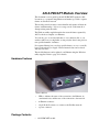
AN-X-PBCAPT Module Overview
This document is a user guide for the AN-X-PBCAPT capture module.
It connects to a computer using Ethernet and makes it possible to capture
frames on a Profibus network.
The module passively monitors network traffic and captures all network
frames, with timestamps. It does not occupy a node on the network or
disrupt existing network traffic.
The Windows utility supplied transfers the network frames captured by
AN-X to the host computer over Ethernet.
You can choose to store network frames to one continuous file, or you
can have AN-X act as a ring buffer, storing only the data for the previous
user-specified number of minutes.
Post-capture filtering lets you select specific frames to store to a text file,
based on the criteria you supply. Filtered network data can be viewed
with any text editor.
The module firmware can be updated over Ethernet using the Windows
utility supplied. Refer to page 54 for details.
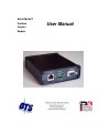
Hardware Features
The module has:
•
LEDs to indicate the status of the connection to the Ethernet, its
own internal state, and the state of the connection to the network
•
an Ethernet connector
•
a 9-pin D-shell connector to connect to the Profibus network
•
a power connector
Package Contents
•
AN-X-PBCAPT module
AN-X-PBCAPT Page 3
•
CD containing software and documentation
Other Requirements
To transfer data over Ethernet requires:
•
100 Mbit/second Ethernet network and hardware
•
Ethernet network should uses switches, not hubs
•
For the higher baud rates (3Mbaud and above), data capture requires
a fast computer, to keep up with the amount of data being
transferred. In addition, you should avoid starting or running other
tasks on the computer, since the overhead may interfere with the data
capture.
To understand the contents of the captured frames, you should be
thoroughly familiar with the Profibus specification and network
protocols.
Modes of Operation
There are three AN-X modes of operation:
•
Boot mode. The AN-X is running its low level startup firmware.
•
Configuration mode. This is the mode when you are updating the
firmware in the AN-X.
•
Production mode. This is the normal runtime mode of operation.
Page 4 AN-X-PBCAPT
November 2011
Installation
Prevent Electrostatic Discharge
The module is sensitive to electrostatic discharge.
WARNING!
Electrostatic discharge can damage integrated circuits or
semiconductors. Follow these guidelines when you handle the module:
•
Touch a grounded object to discharge static potential
•
Do not touch the connector pins
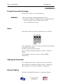
Power
AN-X requires a DC power input of anywhere from 12 to 24 VDC.
Left to right the pins on the power connector are chassis ground, negative
voltage and positive voltage.
The chassis ground should be connected.
Power consumption internally is 300 mA @ 12VDC or 150 mA @
24VDC.
The part number for the power connector is Phoenix MSTB
2.5/3-ST-5.08
Cabling and Termination
Use a standard Profibus cable to connect the module to the network.
The network must be terminated at the physical ends of the network.
There should be two and only two terminators on the network.
Ethernet Cabling
AN-X has a standard RJ-45 connector for connecting to Ethernet.
AN-X-PBCAPT Page 5
If you are connecting AN-X to an existing network through a router,
switch or hub, use a standard Ethernet cable.
If you are connecting directly between a computer and AN-X, use a
crossover cable.
Software Installation
You must uninstall any previous version of the software before you can
install a new version. Use the Windows Control Panel Add and Remove
Programs to remove the old version.
Insert the CD supplied with the AN-X module and run the program
setup.exe on the CD.
Page 6 AN-X-PBCAPT
November 2011
Basic Configuration
The AN-X-PBCAPT module connects a computer or other device on
Ethernet to a Profibus network.
Before you can use the AN-X-PBCAPT, you must configure its network
properties on Ethernet.
No configuration is required on the Profibus network.
Ethernet Configuration
AN-X can be configured to use a static (unchanging) IP address or it can
be configured to obtain its IP address from a DHCP server.
Unless you have control of the DHCP server, in most applications you
will want to configure AN-X to use a static IP address. Otherwise the
DHCP server may assign a different IP address each time AN-X powers
up, and any software that accesses the AN-X module would have to be
reconfigured.
AN-X is shipped with DHCP enabled. If it finds a DHCP server on the
network, the DHCP server assigns it an IP address. You can use the
utility AnxInit to find the IP address that the DHCP server has assigned.
Select Utilities/Locate All AN-X Modules and AnxInit will locate the
AN-X and display its IP address.
If AN-X does not find a DHCP server within about three minutes of
starting up, it reverts to a temporary static IP address of 192.168.0.41 If
AN-X-PBCAPT Page 7
AN-X is using this temporary IP address, it repeatedly flashes the SYS
LED three times followed by a pause.
IMPORTANT! Use this temporary IP address only for initial setup of AN-X. AN-X will
not function for its intended purpose at the temporary IP address.
If you are using multiple AN-X modules, configure one at a time,
especially if there is no DHCP server on the network, since they will all
revert to the same temporary IP address when they fail to find a DHCP
server.
IMPORTANT! If you are connecting AN-X to an existing Ethernet network, consult the
network administrator to obtain information about how you should
configure AN-X and to obtain a static IP address for AN-X.
IMPORTANT! The AN-X must be on the local Ethernet when you set its IP address.
You configure the Ethernet properties using the Windows utility AnxInit
supplied with AN-X.
Use the Configuration/AN-X IP Settings command to start the AN-X IP
configuration wizard, which takes you step by step through the IP
configuration process.
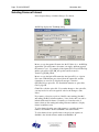
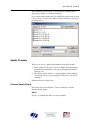
Step 1
In step 1, you identify the AN-X you are configuring.
Page 8 AN-X-PBCAPT
November 2011
1. Select the Ethernet adapter that’s connected to the AN-X. In most
cases there will be just one Ethernet adapter in the computer. The AN-X
must be on the same subnet as the computer.
2. Enter the MAC address of the AN-X you are configuring. This is
printed on the AN-X label. It consists of six pairs of hexadecimal digits,
separated by hyphens. In the example above, it’s 00-0c-1a-00-00-09.
If the AN-X is already online, you can obtain its MAC address using the
Utilities/Locate All AN-X Modules command.
3. Enter the IP address you intend the AN-X to use.
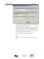
Step 2
In step 2, you choose a method of restarting AN-X to put it in boot mode.
The preferred method is to cycle power on the AN-X. Select the first
option on the screen and click the Next >> button.
The second method, useful if the AN-X in not easily accessible, is to
send it a command over Ethernet. The AN-X must be powered on and
completely running for this method to work. For example, if this is the
first time you are configuring a new AN-X, allow sufficient time for it to
acquire an IP address from a DHCP server or to time out and use its
default IP address (about 3 minutes). Select the second option on the
screen and click the Next >> button.
AN-X-PBCAPT Page 9
Step 3:
Wait for AN-X to enter boot mode. While AnxInit is waiting, the
Next>> button will be disabled. When AN-X is in boot mode, the
Next>> button will be enabled.
If the AN-X does not enter boot mode within about 10 seconds, return to
the previous screens and check the entries.
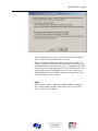
The AN-X TCP/IP Configuration dialog appears.
Page 10 AN-X-PBCAPT
November 2011
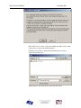
Enter a Host Name for the AN-X. This name is used internally by AN-X
and may be used to identify the AN-X if you have a DNS server on your
network. The name can be from 1 to 31 characters long.
To configure the AN-X to obtain its IP address from a DHCP server on
the network, select Obtain an IP address automatically (DHCP)
To configure the AN-X to use a static IP address, select Use the
following Settings and enter:
•
the desired IP address for the AN-X.
•
the Subnet mask for the AN-X
•
the default gateway for your network.
You must enter a valid default gateway address even if there is no device
at the gateway address on the network.
Click OK to complete the configuration.
If you Cancel the Configuration/AN-X IP Settings command, AN-X is
left running the boot code. Use the Utilities/Restart AN-X command to
restart the AN-X.
Example: Standalone Computer
A typical example is a laptop computer running the AutoMax
programming software and connecting directly to an AN-X to program
an AutoMax processor.
Since you are connecting directly from the computer to AN-X, use a
crossover Ethernet cable.
The following instructions assume Windows 2000. The procedure for
Windows NT and Windows XP is very similar. They also assume that
an Ethernet network card has been installed in the computer and that
AnxInit has been installed on the computer.
TIP
The parameters in this example will work when you set up any
standalone computer to work with AN-X.
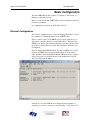
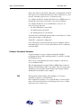
First configure the computer to use a static IP address. From the Start
menu, select Start/Settings/Network and Dialup Connections. Double
click on Local Area Connection.
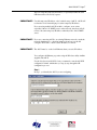
AN-X-PBCAPT Page 11
Click the Properties button.
Double click on Internet Protocol (TCP/IP).
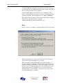
Page 12 AN-X-PBCAPT
November 2011
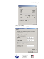
In this example, we will assign the computer an IP address of
192.168.0.10
Set the Subnet mask to 255.255.255.0 (standard mask for the Class C
network address of 192.168.0.x).
Set the Default gateway to 192.168.0.1 (this address does not exist on the
Ethernet network but AN-X requires a valid default gateway entry).
Click OK to accept the settings
Connect the computer to AN-X using the crossover cable.
If this is the first time you have used the AN-X module, it will look for a
DHCP server on the network. It waits about three minutes, then reverts
to a default IP address of 192.168.0.41
Power up the AN-X and wait for the search for a DHCP server to time
out. When the search for a DHCP server times out, AN-X will flash the
SYS LED red three times followed by a pause repeatedly.
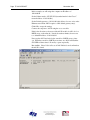
Run AnxInit. Select Utilities/Locate All AN-X Modules and confirm that
the AN-X is found.
AN-X-PBCAPT Page 13
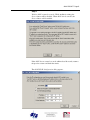
Select Utilities/Select An AN-X and enter the MAC Address and IP
address.
Click OK to accept the setting.
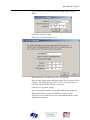
Select Utilities/AN-X IP Configuration.
Enter an IP Address. In this case we chose 192.168.0.20
Enter the same Subnet mask and Default gateway that you entered for the
computer. The default gateway address does not exist on the network
but AN-X requires that the field have a valid entry.
Click Finish to accept the settings.
Select Utilities/Restart AN-X to restart AN-X with the new parameters.
When the AN-X has restarted (SYS LED is solid green), select
Utilities/Locate All AN-X Modules and confirm that the AN-X is found
with the new parameters.
Page 14 AN-X-PBCAPT
November 2011
Reconfiguring an AN-X from an Unknown State
It sometimes happens that an AN-X has been previously configured with
an IP address that causes it to be inaccessible on the current Ethernet
network. To reconfigure it to a known state, run the command
Configuration/AN-X IP Settings to start the AN-X IP Configuration
Wizard and reconfigure AN-X.
AN-X-PBCAPT Page 15
Capturing and Displaying Network Data
Use the Windows AnxPbCapt utility to capture network frames, transfer
them from the AN-X to the computer, store them to hard disk, and view
them.
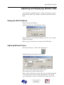
Setting the AN-X IP Address
Select Config/Set AN-X-PBC IP.
AnxPbCapt displays the AN-X-IP Address dialog.
Enter the IP address of the AN-X module that you wish to use to capture
Profibus network data.
Refer to page 6 for information on setting the AN-X IP address.
Capturing Network Frames
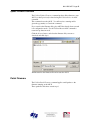
Select Capture/Acquire or click on the Capture button.
AnxPbCapt displays the Capture Control dialog.
Type or browse in the capture file (CaptFile) name.
Select the Baud rate for the Profibus network.
Enter a value for the Stop Error Limit. The stop error limit is the number
of network errors that can occur in the current file before the capture
stops automatically. A value of 1 means that the capture stops on the
Page 16 AN-X-PBCAPT
November 2011
first error. The default value of 0 causes the capture to continue if there
are network errors. If you are using the ring buffer method of capture,
and the error limit is not 0, the error count is reset to 0 each time a new
file is opened.
TIP
You can use the Stop Error Limit to trap a transient or rarely occurring
error. Uncheck Continuous File, set the Keep Time to 2 minutes and set
the Stop Error Limit to 1. The capture will capture network frames until
the first error occurs, then stop.
You can also use the Stop Error limit to capture bursts of errors. Set the
Stop Error Limit to the threshold value, for example 5 or 10, and run the
capture as in the previous example.
If you check Continuous File, the network data is stored in one
continuous file.
If Continuous File is unchecked, AnxPbCapt acts as a ring buffer,
creating new files and deleting old ones. It creates a new file for each
minute the capture is running, naming the file based on the name you
supply and the current time. For example, if you supply the name Test
and the current time is 14:53 (2:53 P.M.), it starts storing data in a file
called Test1453.PbcCapt. The next file is called Test1454.PbcCapt, and
so on.
TIP
For captures over long periods of time, use ring buffer mode.
Continuous capture is better suited for short captures. If you use
continuous capture and the computer is turned off or anything goes
wrong, all captured data could be lost. Using ring buffer mode, if the
computer is turned off, only data for the last minute is lost.
If Continuous File is unchecked, you must enter a value for Keep Time
(min). The keep time is the number of minutes of data that will be
stored. The default is 2. As AnxPbCapt creates each new file, it deletes
the file older that is then older than the keep time. The value of Keep
Time can range from 2 to 1439 minutes.
TIP
If you want to preserve a capture file, move it to another directory, since
otherwise a later capture could inadvertently delete it.
If Auto Dump is checked, AnxPbCapt automatically executes a
Capture/Dump command when the capture ends.
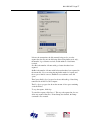
Click Start to begin capturing network frames.
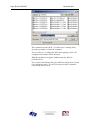
AnxPbCapt displays the Capture Status dialog box.
AN-X-PBCAPT Page 17
It shows the current time, the file currently being used to store the
capture data, the file size, the file being deleted (ring buffer mode only),
the number of good frames received, and the number of bad frames
received.
GoodRx is the number of frames with good status that have been
captured.
BadRx is the number of frames with bad status that have been captured in
the current file. If you are using the ring buffer method of capture and
the stop error limit is non-zero, BadRx is reset each time a new file
opens.
The Capture Buffer Level progress bar shows the backlog of data being
transferred from AN-X to the computer.
The Free Space progress bar shows the amount of free space remaining
on the disk drive.
To stop the capture, click Stop.
To cancel the capture, click Cancel. This stops the capture but does not
delete any captured data files. If AutoDump was checked, the Dump
command is not executed.
Page 18 AN-X-PBCAPT
November 2011
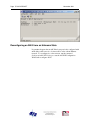
Selecting Frames of Interest
Select Capture/Dump or click the Dump to Text button.
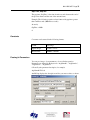
AnxPbCapt displays the TextDump dialog.
Browse or type the capture file name into the FileName box. AnxPbCapt
appends the option file name to the name you supply, and then appends
the extension “.txt”. For example, if the capture file is Test1413.PbcCapt
and the option file is QTS_PB_All.opt, the text file created is
Test1413_QTS_PB_All.txt
Browse or type the Option File name into the OptionFile box. Option
files control which frames are selected from the capture file, and the
format they are saved in. To display all messages, select the
QTS_PB_All.opt option file. For detailed information on option files,
refer to page 20.
Click Edit to edit the option file. If you make changes to the option file,
you may need to browse it in again in order for the changes to take
effect.
If you want to select just a portion of the file, enter starting (StartRef)
and ending (EndRef) reference numbers. Leave both as 0 if you want to
include all the network frames. Normally you locate the event of
interest, then use the starting and ending reference numbers to display
frames around that event.
To select frames from the start of the capture to a specific reference
number, set StartRef to 0 and set EndRef to the desired frame.
To select frames from a specific frame to the end of the capture, set
StartRef to the desired reference number and EndRef to 0.
AN-X-PBCAPT Page 19
If the capture has been saved using the ring buffer method, NumMin
determines the number of consecutive capture files from which frames
are to be extracted. If the capture has been stored to a continuous file, set
NumMin to 1.
After AnxPbCapt stores the selected frames to a text file, you can have it
automatically open the file in your text editor. Check Auto Exec Editor
and browse or type the path to the editor in the Editor Path box.
Click Execute to dump the selected frames to the text file.
Page 20 AN-X-PBCAPT
November 2011
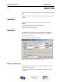
Option Files
Option files are used to define which frames are extracted from captured
data.
Option files consist of various option lines that control which frames are
selected.
Comments
Lines beginning with a semicolon are comments and are ignored.
Example:
;Copyright (c) 2003 Quest Technical Solutions Inc.
;Capture Frame Text Dump Utility
Description
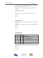
Use the Descrip= option line to display a description in AnxPbCapt.
“Descrip=” is followed by the text to be displayed. For example,
Descrip=Show All Frames
causes the description to appear as shown:
The description can be up to 55 characters long.
Reference Numbers
Each frame has an associated reference number, which can be used to
uniquely identify that frame.
To suppress the inclusion of reference numbers, include the NoRef
option line.
AN-X-PBCAPT Page 21
Example:
NoRef
Frames with Bad Status
Frames with bad status are shown with an asterisk before the frame data.
For example,
357: a 0:00.748,593 *255< 05^
55- 00 00 00 00 00
To suppress the inclusion of frames with bad status, include the NoBad
option line.
However, badly formed frames are automatically displayed, whether they
are selected by the contents of the option file or not, along with some
indication of the cause of the problem. For example,
9289: a 0:00:19.423,410 d
5,666 g
2,545 ....FrmLen?(1)1e
See also Detailed Status on page 29.
Timestamps
The TmeAbs option line sets the format of the frame timestamp. It
specifies the units used to display the timestamp. Possible values are:
hr – hours
mn – minutes
sc – seconds
ms – milliseconds
us – microseconds
ns – nanoseconds
Any character after the unit is included in the timestamp. For example,
hr:mn causes the format of the timestamp to be 12:37, with a colon
between the hours and the minutes.
Example:
TimeAbs hr:mn:sc.ms,us
The frame timestamp can be identified by a leading ‘a’ in the captured
data, for example,
2: a11.000,517 ........ 54<0
SRDH
00
Two other times can be displayed using the same format.
The TimeGap option line displays the gap time, which is the time from
the end of the previous frame to the start of the current frame.
Page 22 AN-X-PBCAPT
November 2011
Example:
TmeGap sc.ms,us
The gap time can be identified by a leading ‘g’ in the capture, for
example,
2: a11.000,517 g 0.000,010 ........ 54<0
SRDH
00
The TmeDelta option line displays the delta time, which is the time from
the start of the previous selected frame to the start of the current frame.
Example:
TmeDelta sc.ms,us
The delta time can be identified by a leading ‘d’ in the capture, for
example,
145: a11.003,248 d 0.000,000
0<125 DL
00
401: a11.010,346 d 0.006,634
0<125 DL
00
The delta time for the first selected frame is set to 0.
TIP
You can use the delta time to display update times for a node. Modify
the option file QTS_PBToNodeFromNode.opt to display the delta time
and include a delta time graph.
Example: Updates from node 125 to node 0
145: a11.003,248 d 0.000,000 d
|
0<125
401: a11.010,346 d 0.006,634 d.............
|
0<125
659: a11.017,016 d 0.006,669 d.............
|
0<125
915: a11.023,651 d 0.006,635 d.............
|
0<125
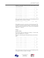
Graphs
The gap time and the delta time can be displayed as a text graph in the
frame data.
The GrphGap option line sets the format of the gap time graph. The
parameters are the full scale width, in characters, and the full scale time,
using the time units described previously. Times are shown graphically
using period ‘.’ characters.
Example: The following option line reserves 20 character spaces,
corresponding to a full scale of 5 ms
GrphGap 20 5ms
The gap time graph can be identified by a leading ‘g’. The end of the
graph can be identified by a ‘|’ character.
AN-X-PBCAPT Page 23
Example of a gap graph, showing the gap times and gap graph, produced
using GrphGap 20,12us:
441: a11.011,321 g 0.000,004 g.......
|
442: a11.011,350 g 0.000,010 g.................. |
443: a11.011,373 g 0.000,004 g.......
0<16
17<0
|
444: a11.011,403 g 0.000,010 g.................. |
445: a11.011,426 g 0.000,004 g.......
446: a11.011,455 g 0.000,010 g.................. |
447: a11.011,478 g 0.000,004 g.......
18<0
DL
SRDH
0<18
19<0
|
448: a11.011,507 g 0.000,010 g.................. |
SRDH
0<17
|
DL
DL
SRDH
0<19
20<0
DL
SRDH
If the gap time graph overflows the given scale, the beginning and end of
the graph are shown as asterisks, for example,
452: a11.011,613 g 0.000,012 g*
*
22<0
SRDH
The GrphDelta option line sets the format of the delta time graph. The
parameters are the full scale width, in characters, and the full scale time,
using the time units described previously. Times are shown graphically
using period ‘.’ characters.
Example:
GrphDelta 20 30us
The delta time graph can be identified by a leading ‘d’. The end of the
graph can be identified by a ‘|’ character.
Example of a delta time graph, showing the delta times and delta time
graph:
33: a11.000,323 d 0.000,022 d...............
|
34: a11.000,352 d 0.000,029 d...................|
35: a11.000,375 d 0.000,022 d...............
|
36: a11.000,404 d 0.000,029 d...................|
37: a11.000,427 d 0.000,022 d...............
|
38: a11.000,456 d 0.000,029 d...................|
39: a11.000,479 d 0.000,022 d...............
|
40: a11.001,509 d 0.000,029 d...................|
0<69
70<0
0<70
71<0
0<71
72<0
0<72
73<0
DL
SRDH
DL
SRDH
DL
SRDH
DL
SRDH
If the delta time graph overflows the given scale, the beginning and end
of the graph are shown as asterisks, for example,
Page 24 AN-X-PBCAPT
November 2011
6: a11.000,621 d 0.000,029 d*
*
56<0
SRDH
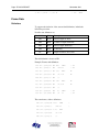
Frame Data
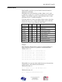
Delimiters
To suppress the inclusion of the start and end delimiters, include the
NoDelim option line.
Possible start delimiters are:
Start delimiter
Value
Description
SD1
0x10
Fixed Length, No Data
SD2
0x68
Variable Length, With Data
SD3
0xa2
Fixed Length, With Data
SD4
0xdc
Token Pass
SC
0xe5
Single Character, Short Ack
The end delimiter is shown as ED.
Example: Frames with delimiters:
144: a11.003,225,638
SD2 125<0
SRDH
00 ED
145: a11.003,248,060
SD2
146: a11.003,277,602
SD1 107<0
147: a11.003,291,394
SD1
0<107 OK
148: a11.003,313,066
SD4
0<0
149: a11.003,328,733
SD1 108<0
150: a11.003,343,524
SD1
0<108 OK
151: a11.003,364,566
SD4
0<0
152: a11.003,381,530
SD2
1<0
SRDH
00 ED
153: a11.003,404,488
SD2
0<1
DL
00 ED
0<125 DL
00 ED
RFDL
ED
ED
RFDL
ED
ED
The same frames, with no delimiters:
144: a11.003,225,638
145: a11.003,248,060
146: a11.003,277,602
125<0
SRDH
0<125 DL
107<0
RFDL
147: a11.003,291,394
0<107 OK
148: a11.003,313,066
0<0
00
00
AN-X-PBCAPT Page 25
149: a11.003,328,733
108<0
RFDL
150: a11.003,343,524
0<108 OK
151: a11.003,364,566
0<0
152: a11.003,381,530
1<0
SRDH
00
153: a11.003,404,488
0<1
DL
00
Source and Destination Nodes
To suppress the display of the destination node, include the NoDst option
line.
To suppress the display of the source node, include the NoSrc option
line.
Frames are shown with the destination node and source node separated
by a less than (<) sign. For example, the following frame has a source of
0 and a destination of 107:
146: a11.003,277,602
107<0
RFDL
The same frame with the destination node suppressed:
146: a11.003,277,602
<0
RFDL
with the source node suppressed:
146: a11.003,277,602
107< RFDL
and finally, with both destination and source node suppressed:
146: a11.003,277,602
RFDL
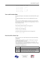
Frame Count Bit or Station Type
This corresponds to bits 4 and 5 in the the Control Octet in the Profibus
specification.
To display frame count bits for a request or station type for a response,
include the ShowFcbTyp option line.
On a command, the frame count bit alternates between 0 and 1. The
value is shown with a ‘v’ if the alternating function of the frame count bit
is valid and with a blank if it is not.
On a response, possible values are:
Station type
Description
ss
Slave station
mn
Master station not ready to enter logical token ring
mr
Master station ready to enter logical token ring
Page 26 AN-X-PBCAPT
November 2011
Station type
mi
Description
Master station in logical token ring
780: a32.013,053,000
6<0
0
RFDL
781: a32.013,067,792
0<6
ss OK
782: a32.013,088,834
0<0
783: a32.013,105,167
1<0
0v SRDH 60{62
784: a32.013,130,714
0<1
ss DL
785: a32.013,171,964
7<0
0
786: a32.013,186,220
0<7
ss OK
787: a32.013,207,428
0<0
788: a32.013,223,095
8<0
0
789: a32.013,238,887
0<8
ss OK
790: a32.013,259,392
0<0
62{60 00 0c 00 00 08 57
RFDL
RFDL
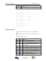
Frame Control Values
The frame control is extracted from the control octet in the network
frame.
To suppress the display of the frame control, include the NoFc option
line.
Possible frame control values:
Name
Value
Description
MTM1
0x40
Cmd: Station Management Time 1
MSRD
0x41
Cmd: Station Management Send and Request Data
MSDN
0x42
Cmd: Station Management Send Data No
Acknowledge
SDAL
0x43
Cmd: Send Data with Acknowledge (Low Priority)
SDNL
0x44
Cmd: Send Data No Acknowledge (Low Priority)
SDAH
0x45
Cmd: Send Data with Acknowledge (High Priority)
SDNH
0x46
Cmd: Send Data No Acknowledge (High Priority)
RDD
0x47
Cmd: Request Diagnosis Data
GSRD
0x48
Cmd: Diagnostic Send and Request Data
AN-X-PBCAPT Page 27
Name
Value
Description
RFDL
0x49
Cmd: Request FDL Status (check for node presence)
MDLY
0x4a
Cmd: Station Management Send and Request Data
Slot Delay
MKEP
0x4b
Cmd: Station Management Send and Request Data
Slot Keep
SRDL
0x4c
Cmd: Send and Request Data (Low Priority)
SRDH
0x4d
Cmd: Send and Request Data (High Priority)
RIR
0x4e
Cmd: Request Ident with Reply
RLSR
0x4f
Cmd: Request LSAP Status with Reply
OK
0x00
Rsp: OK
UE
0x01
Rsp: User Error
RR
0x02
Rsp: No Resource for Send Data
RS
0x03
Rsp: No Service Activated
DL
0x08
Rsp: Ok with Data (Low Priority)
NR
0x09
Rsp: No Response
DH
0x0a
Rsp: Ok with Data (High Priority)
RDL
0x0c
Rsp: No Resource for Send Data, with Data (Low
Priority)
RDH
0x0d
Rsp: No Resource for Send Data, with Data (High
Priority)
MTM2
0xc0
Cmd: Station Management Time 2
Example: Frames showing various frame control values:
144: a11.003,225,638
145: a11.003,248,060
146: a11.003,277,602
125<0
SRDH
0<125 DL
107<0
00
00
RFDL
147: a11.003,291,394
0<107 OK
148: a11.003,313,066
0<0
149: a11.003,328,733
108<0
RFDL
150: a11.003,343,524
0<108 OK
151: a11.003,364,566
0<0
152: a11.003,381,530
1<0
SRDH
00
153: a11.003,404,488
0<1
DL
00
Page 28 AN-X-PBCAPT
November 2011
The same frames with the frame control suppressed:
144: a11.003,225,638
145: a11.003,248,060
146: a11.003,277,602
125<0
00
0<125
00
107<0
147: a11.003,291,394
0<107
148: a11.003,313,066
0<0
149: a11.003,328,733
108<0
150: a11.003,343,524
0<108
151: a11.003,364,566
0<0
152: a11.003,381,530
1<0
00
153: a11.003,404,488
0<1
00
Source and Desination SAPs
To suppress the display of the destination SAP, include the NoDstSap
option line.
To suppress the display of the source SAP, include the NoSrcSap option
line.
Frames are shown with the destination and source SAP separated by a
curly brace { . For example, the first frame shown has a source SAP of
62 and a destination SAP of 60. The second frame has a source SAP of
60 and a destination SAP of 62:
783: a32.013,105,167
1<0
SRDH 60{62
784: a32.013,130,714
0<1
DL
62{60 00 0c 00 00 08 57
The same frames with the destination SAP suppressed:
783: a32.013,105,167
1<0
SRDH {62
784: a32.013,130,714
0<1
DL
{60 00 0c 00 00 08 57
with the source SAP suppressed:
783: a32.013,105,167
1<0
SRDH 60{
784: a32.013,130,714
0<1
DL
62{ 00 0c 00 00 08 57
and finally, with both destination and source SAPs suppressed:
783: a32.013,105,167
1<0
SRDH
784: a32.013,130,714
0<1
DL
00 0c 00 00 08 57
AN-X-PBCAPT Page 29
Detailed Status
If the DetailSts option line is present, detailed status information is
displayed for each frame.
Immediately before the frame data are eight columns, one for each
possible type of status error: stop bit error, parity bit error, invalid start
delimiter, start delimiter repeat error, frame underrun, frame overrun,
checksum incorrect or invalid end delimiter.
For frames with errors, the corresponding column contains a letter that
indicates the type of error. If the column contains a period, there has
been no error or the corresponding type in the frame.
Error name
Value
Column
Letter Description
STSSTP
0x01
1
s
Stop bit error
STSPAR
0x02
2
p
Parity error
STSSD
0x04
3
d
Invalid start delimiter
STSRPT
0x08
4
r
Start delimiter repeat
STSUND
0x10
5
u
Frame underrun
STSOVR
0x20
6
o
Frame overrun
STSCHK
0x40
7
c
Checksum incorrect
STSED
0x80
8
e
Invalid end delimiter
Example:
In the following, frame 2774 has a parity error and an underrun error,
frame 2789 has a stop bit error, a parity error and an invalid start
delimiter, and so on.
2774: a32.529,859,313 .p..u...SD2 SD2 LE?(46) 68
2789: a34.535,961,275 spd.....SD?54 54 d5 d5 d5
2790: a34.536,408,690 .p.ru...SD2 SD2 LE?(19) 68
2791: a34.536,989,699 ..d.....SD?a3 a3 a3 a3 a3
2792: a34.537,046,708 sp.ru...SD2 SD2 LE?(51) 68
If DetailedSts is not present, frames with bad status are shown with an
asterisk in place of the detailed status information.
With detailed status on:
366: a 0.184,865,694 .p..u...SD2 SD2 LE?(16) 68 59…
With detailed status off:
366: a 0.184,865,694 *SD2 SD2 LE?(16) 68 59…
Page 30 AN-X-PBCAPT
November 2011
Frame Data
To suppress the display of the data portion of the frame, include the
NoData option line.
By default, frame data is shown as bytes, in hexadecimal format.
205: a 1.016242644 ........
4<0
SRDH
01 7f 80 ff
Data values can also be shown in several other formats.
If you include the DataUns option line, data values are shown in
unsigned integer format. Values range from 0 to 255.
205: a 1.016242644 ........
4<0
SRDH
1 127 128 255
If you include the DataSgn option line, data values are shown in signed
integer format. Values range from –128 to 127.
205: a 1.016242644 ........
4<0
SRDH
1
127 -128
-1
If you include the Data16 option line, data values are shown in as 16-bit
hexadecimal values. The frame data length must be an even number.
Byte order is high byte-low byte from the original frame.
205: a 1.016242644 ........
4<0
SRDH
017f 80ff
FCS
To include the frame checksum, use the ShowFcs option line.
The checksum is shown at the end of the frame, enclosed in square
brackets.
Example:
3: a11.000,540
0<54
DL
00 [3e]
Equations
You can create an equation to control which frames are stored and
displayed. The beginning of the equation is marked by the option line
showonly. The end of the equation is marked by the option line
consisting of the ‘#’ character. There can be only one equation in an
option file.
Example:
showonly
(STS&STSCHK) = STSCHK
#
Equations consists of keywords, parameters, and constants, connected by
operators.
AN-X-PBCAPT Page 31
TIP
Use parentheses freely in your equations to avoid problems associated
with precedence of operators.
Keywords
The equation can include the following keywords, which are described in
detail below.
Keyword
Description
STS
Frame status
Len
Date length, does not include the checksum
SD
Start delimiter
DA
Frame destination
SA
Frame source
FC
Frame control
DSAP
Destination SAP
SSAP
Source SAP
DataByte[ofs]
Data byte at byte offset ‘ofs’ into the frame data
DataWord[ofs] Data word at byte offset ‘ofs’ into the frame data
CmdArg[num]
Passed parameters, see page 35
GapTme
Gap time, in microseconds, see page 21
Frame Status, STS
The frame status can be one of the following:
Symbolic name
Value
Description
STSSTP
0x01
Stop bit error
STSPAR
0x02
Parity bit error
STSSD
0x04
Invalid Start Delimiter
STSRPT
0x08
Start Delimiter Repeat error
STSUND
0x10
Frame Underrun
STSOVR
0x20
Frame Overrun
STSCHK
0x40
Checksum Incorrect
STSED
0x80
Invalid End Delimiter
Page 32 AN-X-PBCAPT
November 2011
Since multiple bits may be set in STS, mask STS with the bit you wish to
examine before you make any comparisons.
Example: The following equation selects frames with checksum errors.
showonly
(STS&STSCHK) = STSCHK
#
Example: The following equation selects all frames with errors.
showonly
STS <> 0
#
Frame Length, Len
The length refers to the data portion of the frame but does not include the
checksum.
Example: The following equation selects frames with data lenth greater
than 10.
showonly
Len > 10
#
Start Delimiter, SD
Possible start delimiters are:
Start delimiter
Value
Description
SD1
0x10
Fixed Length, No Data
SD2
0x68
Variable Length, With Data
SD3
0xa2
Fixed Length, With Data
SD4
0xdc
Token Pass
SC
0xe5
Single Character, Short Ack
Example: The following equation selects frames with data start delimiter
SD1.
showonly
SD = SD1
#
AN-X-PBCAPT Page 33
Frame Destination Address, DA
You can select frames based on the destination node address.
Example: The following equation selects frames with destination node
25.
showonly
DA = 25
#
Frame Source Address, SA
You can select frames based on the source node address.
Example: The following equation selects frames with source node 2.
showonly
SA = 2
#
Frame Control, FC
The frame control identifies the type of frame. Refer to page 26 for
possible values. The symbolic names can be used in the equation.
Mask the FC byte using the predefind TYPMSK before using the FC in
comparisons.
Example: The following equation selects frames that consist of updates
to slaves or to the master.
showonly
(FC & TYPMASK) = SDNL
#
Destination SAP, DSAP
You can select frames based on the destination SAP. SAP values are
decimal.
Example: The following equation selects frames with destination SAP
62.
showonly
DSAP = 62
#
Page 34 AN-X-PBCAPT
November 2011
Source SAP, SSAP
You can select frames based on the source SAP. SAP values are
decimal.
Example: The following equation selects frames with source SAP 60.
showonly
SSAP = 60
#
Data Values, DataByte[ofs] and DataWord[ofs]
You can use data values in equations. Offsets start from 0 and are
always byte offsets, even for word values.
Example:
Showonly
DataByte[0] = 0x55
#
Byte order in data words is high byte – low byte
For example, to select the following frame based on DataWord[1]
175: a30.120,268,769
SD2
0<125 ss DL
01 02 03 04 8d 8d…
use
showonly
DataWord[1] = 0x0203
#
Parameters
If you have passed in one or more parameters, you can access them using
CmdArg[0], CmdArg[1], CmdArg[2], or CmdArg[3].
Example:
The following equation, from the option file
QTS_PB_ToNodeFromNode.opt, selects frames that have a destination
address obtained from the first parameter and a source address obtained
from the second parameter.
showonly
da=cmdarg[0] && sa=cmdarg[1]
#
See page 35 for information on how to pass in parameters.
AN-X-PBCAPT Page 35
Gap Time, GapTme
The gap time, GapTme, is the time in microseconds between the end of
the previous frame and the start of the current frame.
Example: The following equation selects frames with gap times greater
than 1 milliseconds (1000 microseconds)
showonly
GapTme > 1000
#
Constants
Constants can be entered in the following formats:
Format
Data range
Signed integer
-32768 to 32767
Hexadecimal
0x0000 to 0xFFFF
Passing In Parameters
You can pass in up to four parameters to be used in the equation.
Parameters are defined by the keywords “ArgName0=”, “ArgName1=”,
“ArgName2=”, “ArgName3=”
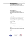
followed by the parameter description, for example,
ArgName0=ToNode
AnxPbCapt displays the description and lets you enter a value, as shown.
Page 36 AN-X-PBCAPT
November 2011
Operators
You can use the following operators to define the equation.
Operator
Description
<>
not equal
!=
not equal
<=
less than or equal
>=
greater than or equal
==
equal
=
equal
>
greater than
<
less than
&&
logical AND
AND
logical AND
||
logical OR
OR
logical OR
!
logical NOT
&
bitwise AND
|
bitwise OR
^
bitwise exclusive OR
*
multiply
/
divide
%
modulus
+
add
-
subtract
~
complement
(
left parenthesis
)
right parenthesis
Sample Option Files
Some of the sample option files provided with the AN-X module
include:
AN-X-PBCAPT Page 37
Option File
Description
QTS_PB_All.opt
Selects all frames
QTS_PB_ToNodeFromNode.opt Selects frames to a specific node
from another node
QTS_PB_DPData.OPT
Selects all DP update frames
QTS_PB_NodeTraffic.OPT
Selects all frames to or from a
specific node
Typically you create a new option file by editing and modifying one of
the sample option files.
Captured Data Format
The following sample output shows a capture, selected using the sample
option file QTS_PB_All.opt. Lines have been truncated for clarity.
46: a 3.040,029 g
SRDH
47: a 3.041,992 g
DL
4<0
0,016 g...........
|........SD2
0<4
0,027 g.................. |........SD2
5<0
0,016 g...........
|........SD2
0<5
0,027 g.................. |........SD2
6<0
8d 8d 8d 8d 8d ED
52: a 3.043,451 g
SRDH
0,027 g.................. |........SD2
8a 8a 8a 8a 8a ED
51: a 3.042,321 g
DL
0<120
8d 8d 8d 8d ED
50: a 3.042,201 g
SRDH
|........SD2
8a 8a 8a 8a ED
49: a 3.042,078 g
DL
0,016 g...........
8d 8d 8d 8d 8d
48: a 3.042,966 g
SRDH
0,027 g.................. |........SD2 120<0
8a 8a 8a 8a 8a
8a 8a 8a 8a 8a ED
Each line starts with a reference number. For example, the first line
shown has a reference number of 46.
Next is the frame timestamp. The first frame has a timestamp of
3.040,029 seconds.
This is followed by the gap time in milliseconds and a graph of the gap
time.
The eight columns after the gap time graph show the detailed status. All
frames shown have good status.
Page 38 AN-X-PBCAPT
November 2011
Next comes the start delimiter. All frames shown have start delimiter
SD2.
This is followed by by the destination and source nodes, separated by a <
sign. Frame 48 has a destination of 4 and a source of 0.
Next is the frame control. Frame 48 has frame control SRDH.
Next comes the frame data. Frame 48 has four bytes of data, each of
which is 8a hexadecimal.
Finally, the frame ends with an end delimiter, ED.
Example 2: Frame with error
The following frame has a parity error and an underrun error, as shown
by the letters in the detailed status. The frame has been truncated for
clarity.
3270: a 5.683,064 g
0,016 g...........
|.p..u...SD2…
Example 3: Frame with SAPs
The following two frames show how service access points (SAPs) are
displayed. Source and destination SAPs are shown separated by a {
brace
87: a 0.016,578 g
0,028 g.................. |........SD2
28<0
SRDH 60{62 ED
88: a 0.016,676 g
DL
0,017 g...........
|........SD2
62{60 00 0c 00 00 08 57 ED
Frame 87 has a source SAP of 62 and a destination SAP of 60
Frame 88 has a source SAP of 60 and a destination SAP of 62.
0<28
AN-X-PBCAPT Page 39
Using AnxInit
AnxInit is a 32-bit Windows application supplied with AN-X to perform
the following functions:
•
Locate and identify AN-X modules on the Ethernet network
•
Select a specific AN-X for configuration
•
Set the IP address and other network parameters for an AN-X
•
Restart an AN-X
•
Display information about the selected AN-X
•
Read the kernel parameters for the selected AN-X
•
Update the flash (low level firmware) on the selected AN-X
•
Update the firmware on the selected AN-X
•
Patch the firmware on the selected AN-X
In addition, it can be used to:
•
clear the AnxInit log
•
copy the contents of the log to the clipboard for use by another
application. This is often useful for technical support
AnxInit Log
AnxInit logs messages in its main window. These messages are often
useful for determining the cause of errors or for technical support.
To clear the log, select Edit/ClearLog.
To copy the contents of the Log to the Windows clipboard so that they
can be pasted into another application, select Edit/Copy.
Page 40 AN-X-PBCAPT
November 2011
AN-X Log
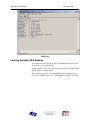
Locating Available AN-X Modules
To locate all accessible AN-X modules on the Ethernet network, select
Utilities/Locate All AN-X Modules.
AnxInit displays a list of the AN-X modules it finds, showing their MAC
IDs, IP addresses and host names.
This command is useful for determining IP addresses when they have
been set by a DHCP server or for confirming that an AN-X is accessible.
AN-X-PBCAPT Page 41
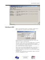
Selecting an AN-X
Before you can perform an operation on an AN-X, you must select it.
Choose Utilities/Select An AN-X to select a specific AN-X.
From the Adapter list, select the network adapter that connects to the
Ethernet network that contains the AN-X.
In the Ethernet MAC Address field, enter the MAC Address of the AN-X
you wish to select. It can be found on the AN-X label or using the
Locate All AN-X Modules command. The format is as shown above, six
pairs of hexadecimal digits separated by hyphens.
In the IP Address field, enter the Ethernet IP address of the AN-X you
wish to select. It can be found using the Locate All AN-X Modules
command. The format is as shown above, four decimal numbers each in
the range 0 to 255.
Both MAC address and IP address must match the settings on the AN-X
in order for communication to occur.
Page 42 AN-X-PBCAPT
November 2011
Click OK to select the AN-X.
The title bar of AnxInit shows the MAC Address and IP Address of the
currently selected AN-X.
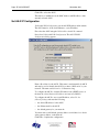
Set AN-X IP Configuration
Utilities/AN-X IP Configuration sets the AN-X IP address and hostname.
The AN-X must be on the local Ethernet to set its IP address.
First select the AN-X using the Utilities/Select An AN-X command.
Next select Utilities/AN-X IP Configuration. The AN-X TCP/IP
Configuration dialog appears.
Enter a Host Name for the AN-X. This name is used internally by AN-X
and may be used to identify the AN-X if you have a DNS server on your
network. The name can be from 1 to 31 characters long.
To configure the AN-X to obtain its IP address from a DHCP server on
the network, select Obtain an IP address automatically (DHCP)
To configure the AN-X to use a static IP address, select Use the
following Settings and enter the following:
•
the desired IP address for the AN-X.
•
the Subnet mask for the AN-X
•
the default gateway for your network.
You must enter a valid default gateway address even if there is no device
at the gateway address on the network.
Click OK to complete the configuration.
AN-X-PBCAPT Page 43
Utilities/AN-X IP Configuration resets the selected AN-X. Use the
Utilities/Restart AN-X to restart the AN-X in production mode.
If you Cancel the Utilities/AN-X IP Configuration command, AN-X is
left running the boot code. Use the Utilities/Restart AN-X command to
restart the AN-X.
Restart an AN-X
Use the Utilities/Restart AN-X command to restart the currently selected
AN-X.
AN-X Info
The Utilities/AN-X Info command provides information about the
currently selected AN-X in the log window.
The information shown:
AN-X Info
Ethernet MAC address
SerNum
Serial number
DaughterID
Daughterboard ID, 2 for AN-X-PBCAPT
BootRev
Boot code version
ConfigRev
Configuration kernel version
ProdRev
Production kernel version
HwRev
Hardware version
FirmwRev
Firmware release version (depends on current
operating mode)
Status
see below
VendorId
Vendor ID
ProdId
Product ID
IpAddrStr
IP address assigned using Utilities/AN-X IP
Configuration
HostName
name assigned using Utilities/AN-X IP
Configuration
In boot mode, FirmwRev, Vendor ID and Product ID and not valid, and
IpAddrStr and HostName are not shown.
Page 44 AN-X-PBCAPT
November 2011
Possible status values are:
Value
Meaning
1
Boot mode
2
Configuration mode
4
Production mode
Read Kernel Parameters
The Utilities/Read Kernel Parameters command displays various
communications parameters for the currently selected AN-X
This command resets the AN-X. You will be warned and given the
opportunity to cancel the command.
The Utilities/Read Kernel Parameters command leaves the AN-X
running the boot code. Use the Utilities/Restart AN-X command to
restart the AN-X in production mode.
Run Config Mode
The Utilities/Run Config Mode command is used to restart the currently
selected AN-X in configuration mode (normally used internally for
updating firmware).
This command is not used in normal operation but may be required for
technical support.
The AN-X is in configuration mode when the SYS LED flashes red
twice, followed by a pause.
To exit configuration mode, use the Utilities/Restart AN-X command to
restart AN-X in production mode.
Update AN-X Flash
The Utilities/Update AN-X Flash command updates the low-level
firmware (boot code, configuration kernel, production kernel).
Files have extension qtf.
AN-X-PBCAPT Page 45
This command resets the AN-X. You will receive a warning and be
given the opportunity to Cancel the command.
If you cancel at the filename dialog, the AN-X has already been reset and
is in boot mode. Use the Utilities/Restart AN-X command to restart it in
production mode.
Update Firmware
There are two ways to update all the firmware in an AN-X module.
1. The Configuration/Firmware Update command starts the firmware
update wizard, which takes you step by step through the firmware
update process.
2. The Utilities/Update Firmware command updates all the firmware
on an AN-X you have selected using the Utilities/Select An AN-X
command.
Firmware files have extension bin.
Firmware Update Wizard
Select the Configuration/Firmware Update command to start the
firmware update wizard.
Step 1:
In step 1, you identify the AN-X you are configuring.
Page 46 AN-X-PBCAPT
November 2011
1. Select the Ethernet adapter that’s connected to the AN-X. In most
cases there will be just one Ethernet adapter in the computer. The AN-X
must be on the same subnet as the computer.
2. Enter the MAC address of the AN-X you are updating. This is printed
on the AN-X label. It consists of six pairs of hexadecimal digits,
separated by hyphens. In the example above, it’s 00-0c-1a-00-00-09.
If the AN-X is already online, you can obtain its MAC address using the
Utilities/Locate All AN-X Modules command.
3. Enter the IP address of the AN-X you want to update
Step 2
In step 2, you choose a method of restarting AN-X to put it in config
mode.
AN-X-PBCAPT Page 47
The preferred method is to cycle power on the AN-X. Select the first
option on the screen and click the Next >> button.
The second method, useful if the AN-X in not easily accessible, is to
send it a command over Ethernet. The AN-X must be powered on and
completely running for this method to work. For example, if this is the
first time you are configuring a new AN-X, allow sufficient time for it to
acquire an IP address from a DHCP server or to time out and use its
default IP address (about 3 minutes). Select the second option on the
screen and click the Next >> button.
Step 3:
Wait for AN-X to enter config mode. While AnxInit is waiting, the
Next>> button will be disabled. When AN-X is in boot mode, the
Next>> button will be enabled.
Page 48 AN-X-PBCAPT
November 2011
If the AN-X does not enter config mode within about 60 seconds, return
to the previous screens and check the entries.
Click the Next>> button, and select the firmware file you want to
download and click Open.
AnxInit transfers the firmware file and restarts the AN-X.
AN-X-PBCAPT Page 49
Update Firmware Command
The Utilities/Update Firmware command updates all the firmware on an
AN-X you have previously selected using the Utilities/Select An AN-X
command.
This command resets the AN-X. You will receive a warning and be
given the opportunity to Cancel the command.
If you cancel at the filename dialog, the AN-X has already been reset and
is in configuration mode. Use the Utilities/Restart AN-X command to
restart it in production mode.
Click the Next>> button, and select the firmware file you want to
download and click Open.
AnxInit transfers the firmware file and restarts the AN-X.
Patch Firmware
The Utilities/Patch Firmware command applies small patches to the
firmware running on the AN-X.
These patch files files have extension pch.
Page 50 AN-X-PBCAPT
November 2011
This command resets the AN-X. You will receive a warning and be
given the opportunity to Cancel the command.
You do not have to reconfigure the AN-X after applying a patch. All
configuration information will be left intact.
When the patch has been applied, AnxInit restarts the AN-X in
production mode.
If you cancel at the filename dialog, the AN-X has already been reset and
is in configuration mode. Use the Utilities/Restart AN-X command to
restart it in production mode.
AN-X-PBCAPT Page 51
Using the Web Interface
The AN-X module contains a webserver capable of communicating with
standard web browsers such as Internet Explorer.
The web interface is used for viewing AN-X logs.
To use the web interface, you need to know the IP address of the AN-X.
Run AnxInit and use the Utilities/Locate All AN-X Devices command to
find all AN-X devices on the Ethernet network.
To access the web interface, start your web browser and type the AN-X
IP address where you normally enter web addresses in the browser.
Log Files
AN-X maintains various logs to record diagnostic and error messages.
Use the Utilities menu in the web interface to view these logs.
System Error Log
The System Error log records errors that occur during AN-X operation.
This log is normally empty.
System Info Log
The System Info Log records informational messages during startup and
normal operation.
View All Logs
Use View All Logs to list and view all the AN-X logs. To view a log
file, double click on the file name.
Administration Menu
The Administration Menu is used to view and edit files on AN-X. It is
password protected and is used only for AN-X technical support.
Page 52 AN-X-PBCAPT
November 2011
Troubleshooting
LEDs
The AN-X-PBCAPT has LEDs that indicate the state of the Ethernet
connection, the overall module state, and the network state
Ethernet LEDs
There are two LEDs that indicate the state of the Ethernet connection.
The orange LED, labelled 100, is on if the link is running at 100
Mbits/second and is off otherwise.
The green Link/Act LED is off if the link is inactive and is on if the link
is active. If activity is detected, the link blinks at 30 ms intervals and
continues blinking as long as activity is present.
SYS LED
The SYS LED is used by the AN-X operating system and software to
indicate the state of operations and errors.
It should be used in conjunction with the logs to locate the cause of
problems.
In the following, red 3 means three red flashes followed by a pause, and
so on.
SYS LED State
Possible cause
Red 2
AN-X is in config mode
Red 3
DHCP configuration failed
Red 4
Fatal application error, check logs for cause
Red 5
Application memory access violation, check logs
Red 6
Application failed, illegal instruction, check logs
Red 7
Application crashed, unknown cause, check logs
Fast red flash
Reconfiguration
Slow red flash
script or application problem during startup
At startup, the SYS LED sequence is:
•
boot code starts – fast flashing red
•
boot code loads a kernel – solid red
•
if the configuration kernel is loaded, 2 red flashes followed by a
pause
AN-X-PBCAPT Page 53
•
if the production kernel loads with no errors, solid green
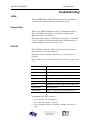
NET LED – Network Status
The NET LED indicates the status of the Profibus network. It operates
only while the capture is running. When no capture is running, the NET
LED is off.
Colour
Meaning
Off
Capture not running
Green
Capture is enabled and AN-X is receiving good frames
Yellow
Capture is enabled but no frames are being received
Red
Capture is enabled and bad frames are being received
Page 54 AN-X-PBCAPT
November 2011
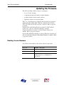
Updating the Firmware
The AN-X operating software consists of several parts:
•
boot code, runs at startup
•
configuration kernel, runs when you update firmware
•
production kernel, runs in normal operation
•
application software, for network capture
The boot code and kernels are supplied in file with extension qtf and are
updated using the AnxInit utility. Run the command Utilities/Update
AN-X Flash and select the file you wish to download. Refer to page 44
for details.
Firmware files contain the application programs for AN-X and have
extension bin. They are downloaded using the command
Configuration/Firmware Update or Utilities/Update Firmware in
AnxInit. Refer to page 45 for details.
Occasionally individual patch files are released. They have extension pch
and are downloaded using the Utilities/Patch Firmware in AnxInit. Refer
to page 49 for details.
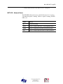
Reading Version Numbers
To read the version numbers of the various software components:
Boot code
AnxInit – AN-X Info
Configuration kernel
AnxInit – AN-X Info
Production kernel
AnxInit – AN-X Info
Firmware
AnxInit – AN-X Info (version depends on
current mode, boot, configuration or
production)
AN-X-PBCAPT Page 55
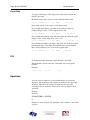
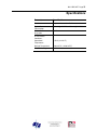
Specifications
Parameter
Specification
Function
Captures frames from Profibus network
Typical Power
Consumption
300 mA @ 12 VDC or 150 mA @ 24 VDC
Maximum Power
dissipation
3.6W
Environmental
Conditions:
Operational
Temperature
0-50°C (32-122°F)
Storage Temperature
–40 to 85°C (–40 to 185°F)
Relative Humidity
5-95% without condensation
Page 56 AN-X-PBCAPT
November 2011
Support
How to Contact Us: Sales and Support
Sales and Technical Support for this product are provided by ProSoft
Technology. Contact our worldwide Sales or Technical Support teams
directly by phone or email:
Asia Pacific
+603.7724.2080, [email protected]
Europe – Middle East – Africa
+33 (0) 5.34.36.87.20, [email protected]
North America
+1.661.716.5100, [email protected]
Latin America (Sales only)
+1.281.298.9109, [email protected].
AN-X-PBCAPT Page 57
Warranty
Quest Technical Solutions warrants its products to be free from defects
in workmanship or material under normal use and service for three years
after date of shipment. Quest Technical Solutions will repair or replace
without charge any equipment found to be defective during the warranty
period. Final determination of the nature and responsibility for defective
or damaged equipment will be made by Quest Technical Solutions
personnel.
All warranties hereunder are contingent upon proper use in the
application for which the product was intended and do not cover
products which have been modified or repaired without Quest Technical
Solutions approval or which have been subjected to accident, improper
maintenance, installation or application, or on which original
identification marks have been removed or altered. This Limited
Warranty also will not apply to interconnecting cables or wires,
consumables nor to any damage resulting from battery leakage.
In all cases Quest Technical Solutions’ responsibility and liability under
this warranty shall be limited to the cost of the equipment. The purchaser
must obtain shipping instructions for the prepaid return of any item under
this Warranty provision and compliance with such instruction shall be a
condition of this warranty.
Except for the express warranty stated above Quest Technical Solutions
disclaims all warranties with regard to the products sold hereunder
including all implied warranties of merchantability and fitness and the
express warranties stated herein are in lieu of all obligations or liabilities
on the part of Quest Technical Solutions for damages including, but not
limited to, consequential damages arising out of/or in connection with
the use or performance of the Product.