1
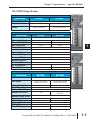
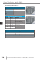
SPECIFICATIONS SPECIALTY MODULES
In This Chapter:
CHAPTER
7
Specialty Module Overview . . . . . . . . . . . . . . . . . . . . . . . . . . . . . . . . . . . . . . . . .7–3
Specialty Modules . . . . . . . . . . . . . . . . . . . . . . . . . . . . . . . . . . . . . . . . . . . . . . . .7–5
Chapter 7: Specifications - Specialty Modules
1
2
3
4
5
6
7
8
9
10
11
12
13
14
A
B
C
D
Notes:
ii
Do-more H2 Series PLC User Manual, 1st Edition, Rev. C - H2-DM-M
Chapter 7: Specifications - Specialty Modules
Specialty Modules Overview
There are several Specialty modules available for use in local and remote I/O bases. These
modules are listed in the tables below and their specifications are found in this chapter. Each
specialty module is identified with a White bar across the front panel as seen below. The
module’s front panel is also equipped with LED status indicators. Depending on the module,
these indicators can show the network health, module health, I/O status or mode of operation
the module is currently in.
Specialty Modules
Module
Part Number
XMT A
XMT B
XMT C
RCV A
RCV B
RCV C
H2-SERIO
RS232 SERIAL PORTS
A
B
C
Specialty Modules
Module Type
(White: Specialty)
Part Number
Description
See Page
H2-CTRIO(2)
High Speed Counter Interface Module
7-5
H2-ECOM100
H2-ERM(100)
H2-EBC100
H2-SERIO(-4)
F2-08SIM
Ethernet Communications Module
7-14
Ethernet Remote Master Module
Ethernet Base Controller
7-22
Serial I/O Module
7-30
8-point Input Simulator Module
7-34
Do-more H2 Series PLC User Manual, 1st Edition, Rev. C - H2-DM-M
1
2
3
4
5
6
7
8
9
10
11
12
13
14
A
B
C
D
7-3
Chapter 7: Specifications - Specialty Modules
1
2
3
4
5
6
7
8
9
10
11
12
13
14
A
B
C
D
Specialty Modules Overview - continued
Specialty Modules Supported
Part Number
H2-CTRIO
H2-CTRIO2
H2-ECOM***
H2-ECOM100
H2-ECOM-F
H2-ERM(100)
H2-ERM-F
Description
Part Number
H2-EBC***
High Speed Counter Interface Module
H2-EBC100
10 Base-T Ethernet Communication Module H2-EBC-F
100 Base-T Ethernet Communication Module H2-SERIO
10 Base-FL Ethernet Communication Module H2-SERIO-4
10/100 Base-T Ethernet Remote Master Module F2-08SIM
High Speed Counter Interface Module
Description
10 Base-T Ethernet Base Controller
100 Base-T Ethernet Base Controller
10 Base-FL Ethernet Base Controller
Serial I/O Module
Serial I/O Module
8-point Input Simulator Module
10 Base-FL Ethernet Remote Master Module
*** The H2-ECOM and H2-EBC modules are discontinued but are still compatible with the new Do-more H2 Series PLC.
Specialty Modules NOT Supported
Part Number
D2-CTRINT
D2-DCM
D2-RMSM
D2-CM
F2-CP128
D2-HPP
7-4
Description
Counter Interface Module
Data Communication Module
Remote I/O Master Module
Expansion Base Controller
CoProcessor Module
Part Number
D2-EM
H2-PBC
F2-DEVNETS-1
F2-SDS-1
DV-1000
Description
Expansion Base I/F Module
Profibus Base Controller
DeviceNet Base Controller
Smart Distributed System Base Controller
DirectVIEW 1000 Timer/Counter access unit
Handheld Programmer
Do-more H2 Series PLC User Manual, 1st Edition, Rev. C - H2-DM-M
Chapter 7: Specifications - Specialty Modules
H2-CTRIO(2)
H2-CTRIO(2) Overview
The H2-CTRIO and H2-CTRIO2 Counter I/O (CTRIO) modules are designed to accept
high-speed pulse input signals for counting or timing applications. These modules also
provide high-speed pulse output signals for servo/stepper motor control, monitoring and
alarming as well as other discrete control functions.
The H2-CTRIO(2) modules offer greater flexibility for applications which call for precise
counting or timing based on input events or for high-speed control output applications. They
can also be used for applications that call for a combination of both high-speed input and
high-speed output control functions.
The H2-CTRIO(2) modules have their own internal microprocessor and operate
asynchronously with respect to the CPU. Therefore, the response time of the on-board
outputs is based on the module’s scan time, not the CPU’s scan time (unless the CPU is
controlling the outputs directly).
H2-CTRIO(2) Terminal Block Layout
+24 VDC
OUTPUTS
CTR
IN
OK
ER
1A
2A
H2-CTRIO2
IN 9-30 VDC 5-12 mA
OUT 5-36 VDC
1.0Amax
per point
1A
2A
1A
0
1
2
3
Input A
Input B
Channel 2
Input C
Input D
2A
1B
Input B
2B
1C
Channel 1
Input C
2C
1D
Input D
2D
1M
1B
2B
Input A
2M
1C
2C
NC
1D
2D
C2
1M
2M
C0
NC
C2
C0
Y2
Y0
Output 2
Y2
Y0
C3
C1
C3
Y3
Y1
Output 0
C1
Output 3
Y3
Y1
Output 1
NOTE: The H2-CTRIO and H2-CTRIO2 modules have the same terminal block layout.
Do-more H2 Series PLC User Manual, 1st Edition, Rev. C - H2-DM-M
1
2
3
4
5
6
7
8
9
10
11
12
13
14
A
B
C
D
7-5
Chapter 7: Specifications - Specialty Modules
H2-CTRIO(2) Configuration
1
2
3
4
5
6
7
8
9
10
11
12
13
14
A
B
C
D
7-6
The module configuration of the H2-CTRIO(2) is done from within the Edit
CTRIO/CTRIO2 Configuration window seen below. The Configure I/O..., Input Filters...,
Discrete Tables... and Pulse Profiles... buttons in the lefthand column will allow you to
configure the input and output functions of the selected module. Refer to the Do-more
Designer Help File for more information on configuration options.
The above window can be accessed once the H2-CTRIO(2) module is added to the I/O
configuration either manually or automatically. See the Verify Hardware Configuration
section of the Getting Started chapter for more information on setting up the I/O
configuration. With the module added, select the Module Configuration(s) entry from the
System Configuration page. Then choose the desired module and select Edit Config.
Do-more H2 Series PLC User Manual, 1st Edition, Rev. C - H2-DM-M
Chapter 7: Specifications - Specialty Modules
H2-CTRIO(2) Specifications
General Specifications
CTR
IN
Specifications
H2-CTRIO
Discrete I/O Points Used
Base Power Required
400 mA Max
275 mA Max
2500V I/O to Logic, 1000V among Input
Channels and All Outputs
1500V I/O to Logic, 1000V among Input
Channels and All Outputs
Isolation
OK
ER
1A
2A
H2-CTRIO2
None (I/O map directly in H2-DM1/E data structure)
H2-CTRIO
2A
Specifications
Inputs
Maximum Input Frequency
Minimum Pulse Width
Input Voltage Range
Maximum Voltage
Input Voltage Protection
Rated Input Current
Minimum ON Voltage
Maximum OFF Voltage
Minimum ON Current
Maximum OFF Current
OFF to ON Response
ON to OFF Response
2C
H2-CTRIO2
8 pts sink/source
2D
2M
C2
100 kHz
250 kHz
5 µsec
0.5 µsec
9-30 VDC
9-30 VDC
Y2
C3
Y3
8 mA typical 12 mA maximum
NC
C0
Y0
C1
Y1
OK
ER
1A
2A
2.0 VDC
5.0 mA
H2-CTRIO2
2.0 mA
less than 3 µsec
less than 0.5 µsec
less than 3 µsec
less than 0.5 µsec
IN 9-30 VDC 5-12 mA
OUT 5-36 VDC
1.0Amax
per point
2A
2C
2D
H2-CTRIO
H2-CTRIO2
2M
C2
Y2
C3
2 channels, 20 Hz to 25 kHz
Pulse/Direction or CW/CCW
Minimum Pulse Width
Output Voltage Range
Maximum Output Voltage
5 µsec
Maximum Load Current
1.0 A
Maximum Leakage Current
Inrush Current
ON State V Drop
Overcurrent Protection
OFF to ON Response
ON to OFF Response
1D
1M
CTR
IN
9.0 VDC
4 pts (sink/source), independently isolated
Pulse Outputs
1C
30 VDC
2B
Outputs
1A
1B
Zener Clamped at 33 VDC
Output Specifications
Specifications
0
1
2
3
IN 9-30 VDC 5-12 mA
OUT 5-36 VDC
1.0Amax
per point
2B
Input Specifications
H2-CTRIO
+24 VDC
OUTPUTS
2 channels, 20 Hz to 250 kHz
Pulse/Direction or CW/CCW
Y3
1A
1B
1C
1D
1M
NC
C0
Y0
C1
Y1
0.5 µsec
5-36 VDC
36 VDC
1.0 A at 23°C
0.5 A at 60°C
100 µA
5.0 A for 20 ms
0.3 VDC or less
2.0 A for 10 ms
0.45 VDC or less
Yes
less than 3 µsec
less than 3 µsec
less than 1 µsec
less than 1 µsec
Do-more H2 Series PLC User Manual, 1st Edition, Rev. C - H2-DM-M
+24 VDC
OUTPUTS
0
1
2
3
1
2
3
4
5
6
7
8
9
10
11
12
13
14
A
B
C
D
7-7
Chapter 7: Specifications - Specialty Modules
1
2
3
4
5
6
7
8
9
10
11
12
13
14
A
B
C
D
7-8
H2-CTRIO(2) LED Indicators
CTR
IN
H2-CTRIO(2) LED Descriptions
OK
ER
1A
2A
0-3
Module OK
OK
ER
1A
2A
User Program Error
Channel 1 Status
Channel 2 Status
H2-CTRIO(2) LED Diagnostic Definitions
LED ER
CTR
IN
Description
Blinking
Blinking
Blinking
OFF
OFF
Blinking
0
1
2
3
H2-CTRIO
Output Status
LED OK
+24 VDC
OUTPUTS
OK
ER
1A
2A
Boot Mode - Used for Field OS Upgrades
Program Mode
Module Self-Diagnostic Failure
(Blinks may be coded by counts)
OFF
ON
Module Error Due to Watchdog Timeout
OFF
OFF
No Power to Module
ON
OFF
All is well - RUN Mode
ON
ON
+24 VDC
OUTPUTS
0
1
2
3
H2-CTRIO2
Hardware Failure (H2-CTRIO)
Not Used (H2-CTRIO2)
H2-CTRIO(2) LED Diagnostic Definition
1A/2A
Blinking 7 times per second
Input is configured as Counter and is changing
Following state of input
Input is not configured as counter
0-3
Follow actual output state: ON = output is passing current
Do-more H2 Series PLC User Manual, 1st Edition, Rev. C - H2-DM-M
Chapter 7: Specifications - Specialty Modules
H2-CTRIO(2) Jumper Setup
Jumpers are provided to connect input commons or outputs/output commons. Use of these
jumpers is not necessary to set up the CTRIO(2) module. The jumpers are provided solely
for convenience in wiring.
NOTE: The location of the jumper board and pin assignments are different between the CTRIO and CTRIO2.
H2-CTRIO(2) Jumper Functions
H2-CTRIO2
Function
H2-CTRIO
Install jumper to internally connect the input commons 1M and 2M in
order to reduce wiring if appropriate.
1M-2M
Y0-Y1
Install jumper(s) to internally connect Y0 to other Y terminals in order
to reduce wiring if appropriate. Connect wire at Y0.
Y0-Y2
Y0-Y3
C0-C1
Install jumper(s) to internally connect C0 to other C terminals in
order to reduce wiring if appropriate. Connect wire at C0.
C0-C2
C0-C3
C3-C0
C3-C1
Install jumper(s) to internally connect C3 to other C terminals in
order to reduce wiring if appropriate. Connect wire at C3.
C3-C2
1M
M
Y0
C00
2M
2M
Y1
Y1
Y2
Y2
Y33
C1
C2
C3
C3
H2-CTRIO
C3
C3
C3
Y2
Y3
Y1
M2
H
H
H
L
L
L
C0
C2
C1
Y0
Y0
Y0
M11
1
2
3
4
5
6
7
8
9
10
11
12
13
14
A
B
C
D
H2-CTRIO2
Do-more H2 Series PLC User Manual, 1st Edition, Rev. C - H2-DM-M
7-9
Chapter 7: Specifications - Specialty Modules
Wiring Information
CTR
IN
OK
ER
1A
2A
1B
2B
1C
2D
1M
-
2M
- +
C2
NC
+
+
–
2C
2M
L
Y0
–
+
C2
Y2
C3
Y3
C1
+
L
Y3
+
-
2D
C3
–
2A
2B
C0
Y2
L
+
+
+
–
-
–
L
0
1
2
3
IN 9-30 VDC 5-12 mA
OUT 5-36 VDC
1.0Amax
per point
1D
+
+24 VDC
OUTPUTS
H2-CTRIO
2C
+
The H2-CTRIO(2) module has two
independent input channels, each consisting of
four optically isolated input points (pts. 1A-1D
on common 1M and pts. 2A-2D on common
2M). The inputs can be wired to either sink or
source current.
The module has four optically isolated output
points (Y0-Y3 with isolated commons C0-C3,
respectively) that can be wired to either sink or
source current. Remember that the internal
jumpers can be used to connect the input
commons or output commons together.
–
–
+
1A
1B
1C
1D
1M
NC
C0
Y0
C1
Y1
Y1
–
NOTE: Field device wiring must be compatible with the module configuration configured in Do-more
Designer
DC type field devices are configured to either sink or source current. This affects the wiring
of the device to the CTRIO module as seen below.
PNP Field Device (source)
NPN Field Device (sink)
This drawing illustrates wiring that is
typical for Channel 1 terminals 1A, 1B,
1C, and 1D. The same circuitry is also
present at the corresponding
Channel 2 terminals.
24VDC
1
2
3
4
5
6
7
8
9
10
11
12
13
14
A
B
C
D
1A
2A
7-10
+
1A
Sensing Circuit
This drawing illustrates wiring that is
typical for Channel 1 terminals 1A, 1B,
1C, and 1D. The same circuitry is also
present at the corresponding
Channel 2 terminals.
1A
Sensing Circuit
24VDC
- +
1M
1M
The same circuitry is present at the
corresponding Channel 2 terminal.
The same circuitry is present at the
corresponding Channel 2 terminal.
H2-CTRIO(2) Wiring Considerations
When wiring CTRIO modules, please consider the following:
•
•
•
•
Keep encoder input wiring as short as possible
Route wiring to avoid any runs parallel to noisy cables.
Route wiring to avoid the proximity of noisy devices.
Use shielded, twisted pair cables, such as:
Suggested Cabling
Type of Cable Supplier/Part Number
3 pair, twisted,
overall shield
1 pair, twisted,
overall shield
Supplier/Part Number
AutomationDirect/L19853-XXXX
Belden/8103
AutomationDirect/L19827-XXXX
Belden/9841
Do-more H2 Series PLC User Manual, 1st Edition, Rev. C - H2-DM-M
Chapter 7: Specifications - Specialty Modules
H2-CTRIO(2) Input Wiring Examples
CTR
IN
ISOLATION
BARRIER
+24 VDC
OUTPUTS
TTL Quadrature Encoder Field Wiring
IN 9-30 VDC 5-12 mA
OUT 5-36 VDC
1.0 max
per point
2A
2B
2C
2D
2M
C2
Y2
C3
Y3
FC-ISO-C
Brown: Power source*
+Ai
Blue: 0 V
ENCODER
-Ai
+Bi
Black: OUT A
-Bi
Purple: OUT A
+Zi
White: OUT B
COM
-Zi
Differential Line
Driver Encoder
1A
1B
1C
1D
1M
NC
C0
Y0
C1
Y1
COM
Gray: OUT B
Orange: OUT Z
V+
0V
Yellow: OUT Z
Shield: Ground
PLC High Speed Counter
Interface Module
Ao
+
-24VDC
Ao
Bo
* Use separate power supply to maintain isolation
Bo
Zo
Zo
0V
0V
TTL Input Wiring Example
NPN
General Purpose Transistor
1A
2A
C
TTL Device
1B
2B
B
HFE > 100
1C
2C
0.1W
10%
E
1D
10K
2D
1M
2M
NC
C2
C0
C
Y2
Y0
HFE > 100
C3
C1
TTL Device
B
E
10K
0.1W
10%
Y3
+
9 - 30VDC
Y1
1
2
3
4
5
6
7
8
9
10
11
12
13
14
A
B
C
D
Do-more H2 Series PLC User Manual, 1st Edition, Rev. C - H2-DM-M
7-11
Chapter 7: Specifications - Specialty Modules
Quadrature Encoder Wiring Example
1A
2A
A
1B
A
B
2B
B
1C
Z
2C
Z
Power
+
-
Gnd
9-30VDC
1D
Power
2D
1M
2M
NC
C2
+
-
9-30VDC
1
2
3
4
5
6
7
8
9
10
11
12
13
14
A
B
C
D
Gnd
C0
Y2
PNP Open
Collector or
Totem Pole
NPN Open
Collector
Y0
C3
C1
Y3
Y1
NPN Open Collector Device
Encoder
Shield twisted
pair
CITRIO2
1A
+
_
1M
Ground shield this
end only
PNP Open Collector Device
7-12
p
Encoder
+
Shield twisted
pair
CITRIO2
1A
_
1M
Ground shield this
end only
Do-more H2 Series PLC User Manual, 1st Edition, Rev. C - H2-DM-M
Chapter 7: Specifications - Specialty Modules
H2-CTRIO(2) Output Wiring Examples
The four outputs are individually isolated so each output can be used
to break the high or the low side of a DC load seperately
+
Cn (where n=0, 1, 2, 3)
+5 to 36VDC
+
_
Load
CTRIO
Output
Yn (where n=0, 1, 2, 3)
+5 to 36VDC
+
_
-
Cn (where n=0, 1, 2, 3)
CTRIO
Output
+
Load
-
Yn (where n=0, 1, 2, 3)
1A
2A
1B
2B
1C
2C
1D
2D
1M
Step Amplifier
OPTO Power
5-36VDC
+ -
Step Amplifier
2M
NC
5-36VDC
- +
C2
OPTO Power
C0
Pulse (or CW)
Pulse (or CW)
Y2
Y0
Direction (or CCW)
Direction (or CCW)
C3
C1
Y3
Y1
WARNING: The above example assumes that the Step Amplifier interface is made up of optocoupler
LEDs (common anodes at the “OPTO Power” terminal) with internal current limiting resistors. This is
a standard method, but you must consult your step amplifier documentation to ensure that this method
is applicable.
Do-more H2 Series PLC User Manual, 1st Edition, Rev. C - H2-DM-M
1
2
3
4
5
6
7
8
9
10
11
12
13
14
A
B
C
D
7-13
Chapter 7: Specifications - Specialty Modules
H2-ECOM100
1
2
3
4
5
6
7
8
9
10
11
12
13
14
A
B
C
D
7-14
H2-ECOM100 Overview
The H2-ECOM100 Ethernet Communication (ECOM) module provides high-speed
Ethernet connections for the Do-more PLC. These modules are easy to set up and install on
10/100BaseT (twisted pair, copper wire) Ethernet networks.
LEDs on the face of each module give vital information about the status of the module and
the communications link. The 10/100BaseT modules use standard RJ45 modular
connectors.
You can use the ECOM modules to share data between two or more Do-more PLCs or
between Do-more PLCs and personal computers. The H2- ECOM100 additionally allows
client/server communications with other Ethernet devices using the MODBUS TCP/IP
protocol. Communication between PLCs and MODBUS TCP/IP devices is accomplished by
using the MRX/MWX instructions.
You can use a personal computer equipped with a 10/100BaseT network adapter card and
NetEdit3 software to configure the ECOM module over the network. Once configured, the
H2-ECOM100 module allows you to program your Do-more PLC over the Ethernet
network using the Do-more Designer programming software. The NetEdit3 utility installs
with the Do-more Designer software and can be very useful for troubleshooting certain
communication problems.
NOTE: We recommend using a dedicated network for your PLC control applications.
H2-ECOM100 Specifications
H2-ECOM100 Ethernet Communications Module
Specifications
Communications
Data Transfer Rate
H2-ECOM100
10/100Base-T Ethernet
100 meters (328 ft)
Ethernet Port
RJ45
Power Consumption
100MBIT
H2-ECOM100
100 Mbps max.
Link Distance
Ethernet Protocols
STATUS
LINKGD
ACTIVE
ERROR
10/100 BASE-T
BASE
SE-T
-T
ETHERNET
HERNET PORT
TCP/IP, IPX, Modbus TCP,
DHCP, HTML configuration
300 mA @ 5 VDC
Do-more H2 Series PLC User Manual, 1st Edition, Rev. C - H2-DM-M
Chapter 7: Specifications - Specialty Modules
H2-ECOM100 LED Indicators
H2-ECOM100 LED Descriptions
Status
Description
Indicator
STATUS
LINKGD
ACTIVE
ERROR
100MBIT
ON (Green)
Module is powered up and functional
OFF
Module powerup failed
ON (Green)
Properly connected to network
STATUS
LINKGD
ACTIVE
ERROR
OFF
Not connected to network or incorrect configuration
H2-ECOM100
ON or FLASHING (Red)
Active Network Data
OFF
Network Idle
ON or FLASHING (Red)
OFF
ON
A fatal error has occurred
No error present
100Base T Frequency detected
OFF
(with ACTIVE LED ON) - 10Base T Frequency detected
100MBIT
H2-ECOM100 Network Identifiers
Each module must be assigned at least one unique identifier to make it possible for other
devices to recognize it on the network. There are four identifiers possible with the ECOM
modules:
• Module ID
• Name
• IP (Internet Protocol) Address
• Ethernet (MAC) Address
The first three are user selectable but the MAC address is set at the factory. The type of
identifier chosen depends on the requirements of your particular application. PC-to-PLC
communication typically uses one type of identifier while PLC-to-PLC communication may
require another. The following table summarizes Network Identifiers and their uses:
Network Identifiers
Identifier
How to Set
Format
Communication
Notes
DIP Switch
Number 1-63
PLC-to-PLC or PC-to-PLC
Disables Module ID in NetEdit3
NetEdit3
Number 1-90
PLC-to-PLC or PC-to-PLC
DIP Switch must be set to “0”
NetEdit3
Number 1-999,999,999
PC-to-PLC only
>90 (Not for PLC-to-PLC)
Name
NetEdit3
32 Alphanumeric Characters
PC-to-PLC only
HMI software may have restrictions
IP Address
NetEdit3
(PLC-to-PLC
4 sets of numbers, up to three PC-to-PLC,
your Network Administrator for
Client/Server using TCP/IP or See
digits each (192.168.76.3)
IP addresses
Modbus TCP protocols)
Module ID
Ethernet (MAC) Address Set at Factory
12 Hex digits
PC-to-PLC only
Factory assigned for IPX
Do-more H2 Series PLC User Manual, 1st Edition, Rev. C - H2-DM-M
7-15
1
2
3
4
5
6
7
8
9
10
11
12
13
14
A
B
C
D
Chapter 7: Specifications - Specialty Modules
1
2
3
4
5
6
7
8
9
10
11
12
13
14
A
B
C
D
7-16
Module ID
A Module ID is required for PLC-to-PLC communication and it can be set in two ways:
• using the DIP switches on the module
• using the configuration tools in NetEdit3
• HTML configuration (after IP address is
assigned to module using NetEdit3)
Use the DIP switches if you want the
ability to install or change modules
without having to use a PC to set the
Module ID. Set the module’s DIP
switches, install the module in the base and
apply power. The Module ID will be
accepted on powerup and your ECOM
will be ready to communicate.
Binary Value
(32) (16) (8) (4) (2) (1)
Not
Used
ON
25 24 23 22 21 20
7 6 5 4 3 2 1 0
Name
A Name makes it easy to recognize the PLC by its function. An example of a Name is
“PumpStationOne”, as seen in the diagram below. The Name can be up to 32 alphanumeric
characters in length.
Do-more
PLC
NOTE: Some HMI software products
will not accept Names with numbers
as the first character, spaces or
certain other non-alphanumeric
ASCII characters. Also, your HMI
product may not accept Names
longer than 16 characters. Consult
your HMI product documentation
about its naming conventions.
ECOM
Module
ERM
Module
GS-EDRV100
H2-DM1E
AC
Drive
Pump Station One
IP Address
An IP Address can be assigned
to the ECOM module if your
network requires one. Usually,
Pump Station One
the IP Address is required in
cases where PLCs are sharing
the same network with PCs,
and some of the PCs are
carrying out functions unrelated to PLC control. Normally, a network administrator will
assign an IP Address to each device on the network. Use NetEdit3 to configure the assigned
IP address to the ECOM.
Do-more H2 Series PLC User Manual, 1st Edition, Rev. C - H2-DM-M
Chapter 7: Specifications - Specialty Modules
NOTE: You must use an IP address if you are using the UDP/IP or Modbus TCP protocol.
The module ships from the factory with an IP Address of 0.0.0.0. This is not a usable IP
Address for normal communication. It only serves as a default setting which can be changed
using NetEdit3. The valid setting for each field is 1 through 254. You do not have to change
the default IP Address unless you are using the IP Address to link to your ECOM module.
The default setting does not cause conflicts with other network communications. If you
change the default IP Address for linking to other network devices, you must change all four
“0” fields.
Example IP Addresses - If the Client (PC/ECOM) Subnet Mask is 255.255.0.0 and the
Client has an IP Address of 192.168.50.2, then the following are valid Server IP Addresses:
• 192.168.55.5 - Valid Server ECOM IP Address
• 192.168.70.15 - Valid Server ECOM IP Address
The subnet mask determines which fields must match by assigning a 255 to that field. In the example
above, the first two fields are masked with a 255, therefore valid Server IP Addresses must match the
first two fields of the Client IP or 192.168. The last two fields are allowed to vary because they are
masked with a “0”.
WARNING: It is extremely important not to have duplicate IP Addresses on your network. If you are
using the IP Address to link the ECOM to any network devices (PCs or PLCs), the ECOM must have a
unique number.
Ethernet (MAC) Address
A unique Ethernet (MAC) Address is assigned to each module at the factory and will not
change. It is printed on a label attached to each ECOM module. The Ethernet (MAC)
Address is recognized by NetEdit3. The Ethernet (MAC) Address is a twelve digit number
with no deliberate relationship to your network or functional areas of your plant. Typically,
the MAC address is not a convenient and easily remembered identifier for your ECOM
module.
Host Auto. Products
H2-ECOM
MFG:IES
0602
4D
00.E0.62.20.1B.95
5VDC
60DegC
LISTED
33ZL
Using Multiple Network Identifiers
You can use IP Addresses to satisfy network requirements, the Name identifier for PCs
running HMI software and Module IDs for PLCs to share data among themselves. Using one
type of identifier does not limit your use of the other identifier types.
Do-more H2 Series PLC User Manual, 1st Edition, Rev. C - H2-DM-M
1
2
3
4
5
6
7
8
9
10
11
12
13
14
A
B
C
D
7-17
Chapter 7: Specifications - Specialty Modules
H2-ECOM100 Network Layouts
1
2
3
4
5
6
7
8
9
10
11
12
13
14
A
B
C
D
The ECOM Ethernet network is a peer-to-peer network. Using Read (RX) or Write (WX)
instructions, any PLC on the network can initiate communications with any other PLC on
the network. A PC running our KEPDirect software can also initiate communications with
any ECOM that is on the same network, but a PLC cannot initiate communication with the
PC. An ECOM can sequence through communication connections with each PLC on the
network, one at a time.
The ECOM products inherently support two network layouts:
point-to-point and star. The point-to-point layout can be used
to link together two PLCs or a PC and a PLC. A switch
connects multiple networkable devices into a star topology.
Multiple switches are used to modify the star topology so that it
becomes a star-bus-star topology. See the figures below.
Point-to-Point
7-18
H2-DM1E
TERM
RUN
STOP
USB
PGM
PORT
RS-232
SERIAL
E
1 T
0 H
/ E
1 R
0 N
0 E
T
Switches can connect together to make it possible to connect more devices to the network or
to extend the range of the network.
Do-more H2 Series PLC User Manual, 1st Edition, Rev. C - H2-DM-M
Chapter 7: Specifications - Specialty Modules
H2-ECOM100 Network Cabling
The H2-ECOM100 module supports 10/100BaseT standard cabling consisting of copper
wire twisted pairs.
10/100BaseT
Unshielded TwistedPair cable with
RJ45 connectors
STATUS
LINKGD
ACTIVE
ERROR
100MBIT
H2-ECOM100
10/100 BASE-T
ETHERNET PORT
10/100 BaseT Networks
The cable used to connect a PLC (or PC) to an Ethernet switch is called a patch (straightthrough) cable. The cable used to connect together two PLCs, a PC and a PLC, or two
switches is a crossover cable. We recommend that you purchase cables pre-assembled with
connectors for convenient and reliable networking.
NOTE: The above diagram illustrates the standard wire positions in the RJ45 connector. We recommend all
ECOM 10/100BaseT cables to be Category 5, UTP cable.
Do-more H2 Series PLC User Manual, 1st Edition, Rev. C - H2-DM-M
1
2
3
4
5
6
7
8
9
10
11
12
13
14
A
B
C
D
7-19
Chapter 7: Specifications - Specialty Modules
1
2
3
4
5
6
7
8
9
10
11
12
13
14
A
B
C
D
7-20
Cable Lengths
The maximum distance per 10/100BaseT cable segment is 100 meters or 328 feet. Switches
allow multiple 100 meter cable segments to be joined together increasing the allowable
distance. For example, two switches connected together adds an additional 200 meters to the
system, for a total range of 300 meters.
Maximum Number of ECOM Modules on the Network
The maximum number of nodes that can be connected to a 10/100BaseT network is a
function of the topology used in constructing the network. Therefore, it is not possible to
state an absolute maximum number of nodes that would apply in all cases.
The IEEE 802.3 specification defines the maximum node limit for an Ethernet segment in
terms of the ability to detect and avoid data collisions. A “legal” network can have any
number of devices provided that they can:
• detect all data collisions that may occur during the communication process and
• respond to these collisions appropriately.
You must take into consideration the network limitations imposed by all cabling and network
devices. Consider the limitations imposed on your network if your network uses:
• a combination of cabling standards, such as 10/100 BaseT and 10Base2, or
• intermediate devices, such as switches or routers.
Do-more H2 Series PLC User Manual, 1st Edition, Rev. C - H2-DM-M
Chapter 7: Specifications - Specialty Modules
Each ECOM module can be assigned a Module ID ranging from 1 to 999,999,999.
Theoretically, you could have this many Ethernet modules coexisting on a single network.
Other network limitations would restrict the network size before reaching this limit. For the
majority of network PLC applications there is practically no limit to the number of ECOM
modules you can access from the NetEdit3 or Do-more Designer software. There is a node
limit for PLC-to-PLC communications. The network Read and Write instructions performed
by the initiating (master) PLC are only capable of accessing PLCs with Module IDs of 1
through 90. This effectively sets the maximum number of nodes available for PLC-to-PLC
communications at 90.
WARNING: We recommend against connecting Ethernet modules to the same network that serves as
your primary office network. While Ethernet networks can handle a very large number of data
transmissions, and normally handle them very quickly, heavy Ethernet traffic can adversely affect the
reliability and speed of the network.
Do-more H2 Series PLC User Manual, 1st Edition, Rev. C - H2-DM-M
1
2
3
4
5
6
7
8
9
10
11
12
13
14
A
B
C
D
7-21
Chapter 7: Specifications - Specialty Modules
H2-ERM(100)/ H2-EBC100
1
2
3
4
5
6
7
8
9
10
11
12
13
14
A
B
C
D
7-22
H2-ERM(100) Overview
Expanding I/O beyond the local chassis is useful for a system which has a sufficient number
of sensors and other field devices located a relatively long distance from the CPU. The
Ethernet Remote Master H2-ERM(100) connects Do-more CPU systems to slave I/O over a
high-speed Ethernet link.
Each ERM module can support up to 16 H2-EBC systems, 16 Terminator I/O EBC systems,
or 16 fully expanded H4-EBC systems. Of course, combinations are fine, too.
NOTE: Applications requiring an extremely large number of T1H-EBC analog I/O or H4-EBC 16-channel
analog I/O, could exceed the buffer capacity of a single H2-ERM(100) module. In these cases, an additional
H2-ERM(100) may be required.
The ERM connects to your control network using Category 5 UTP cables for cable runs up
to 100 meters (328 ft.). Use Ethernet switches to extend distances and expand the number of
nodes.
The PLC, ERM and EBC slave modules work together to update the remote I/O points.
These three scan cycles are occurring at the same time, but asynchronously. Critical I/O
points that must be monitored every scan are best placed in the CPU base.
It is highly recommended that a dedicated Ethernet remote I/O network be used for the
ERM and its slaves. While Ethernet networks can handle a large number of data transactions,
and normally handle them very quickly, heavy Ethernet traffic can adversely affect the
reliability of the slave I/O and the speed of the I/O network. Ensure ERM networks, multiple
ERM networks and ECOM/office networks are isolated from one another.
H2-ERM(100) Specifications
H2-ERM(100) Ethernet Remote I/O Master Module
Specifications
Module Type
Slaves per ERM
Communications
Data Transfer Rate
Ethernet Port
Power Consumption
Operating Environment
H2-ERM
16 Max
10BaseT Ethernet
LINKGD
ACTIVE
ERROR
LINKGD
ACTIVE
ERROR
H2-ERM
H2-ERM100
10/100BaseT Ethernet
10Mbps
100Mbps
RJ45
320mA @5VDC
300mA @5VDC
10BASE-T
ETHERNET PORT
0ºC to 60ºC (32ºF to 140ºF), 35% to 95% humidity (noncondensing)
100 meters (328 ft)
Link Distance
Ethernet Protocols
H2-ERM100
Ethernet Communications Master Module
TCP/IP, IPX
TCP/IP, IPX
Modbus TCP/IP, DHCP,
HTML configuration
Do-more H2 Series PLC User Manual, 1st Edition, Rev. C - H2-DM-M
10/100BASE-T
ETHERNET PORT
Chapter 7: Specifications - Specialty Modules
H2-ERM(100) LED Indicators
H2-ERM(100) LED Descriptions
Indicator
Status
Description
LINKGD
ACTIVE
ERROR
ON
Communications Link OK
ON
Network Active
OFF
Network Idle
LINKGD
ACTIVE
ERROR
ON or Flashing
Fatal Error Detected
H2-ERM100
H2-EBC100 Overview
The Ethernet Base Controller (EBC) serves as an interface between the master control system
and remote I/O modules. The control function is performed by the master controller, not the
EBC slave. The EBC occupies the CPU slot in the base and communicates across the
backplane to input and output modules. The function of the EBC is to:
•
•
•
•
•
process analog and digital input signals
format the I/O signals to conform to the Ethernet standard
transmit input signals to the network master
receive and translate output signals from the network master
distribute the output signals to the appropriate output module in the base
The H2-EBC100 module supports industry standard 10/100BaseT Ethernet
communications.
NOTE: The RS-232 serial port on the EBC module cannot be used when the EBC module is part of the Domore controller system.
H2-EBC100 Specifications
Specifications
Communications
Data Transfer Rate
Link Distance
Ethernet Port
H2-EBC100
10/100BaseT Ethernet
100Mbps max.
100 meters (328 ft)
Serial Port*
RJ45
TCP/IP, IPX/Modbus TCP/IP, DHCP, HTML
configuration
RJ12
Serial Protocols
K-Sequence, ASCII IN/OUT, Modbus RTU
Ethernet Protocols
Power Consumption
STATUS
LINKGD
ACTIVE
ERROR
100MBIT
TXD
RXD
H2-EBC100
RS 232
RS-232
SERIAL PORT
300mA @ 5VDC
* The serial port on the EBC modules cannot be used when the H2-DM1/E is the
network master.
10/100 BASE-T
ETHERNET PORT
Do-more H2 Series PLC User Manual, 1st Edition, Rev. C - H2-DM-M
1
2
3
4
5
6
7
8
9
10
11
12
13
14
A
B
C
D
7-23
Chapter 7: Specifications - Specialty Modules
H2-EBC100 LED Indicators
1
2
3
4
5
6
7
8
9
10
11
12
13
14
A
B
C
D
H2-EBC100 LED Descriptions
Status
Description
Indicator
STATUS
LINKGD
ACTIVE
ERROR
100MBIT
TXD
RXD
ON (Green)
Module is powered up and functional
OFF
Module powerup failed
ON (Green)
Properly connected to network
STATUS
LINKGD
ACTIVE
ERROR
100MBIT
TXD
RXD
OFF
Not connected to network or incorrect configuration
H2-EBC100
ON or FLASHING (Red)
Active Network Data
OFF
Network Idle
ON or FLASHING (Red)
OFF
ON
A fatal error has occurred
No error present
100Base T Frequency detected
OFF
(with ACTIVE LED ON) - 10Base T Frequency detected
FLASHING (green)
Serial port is transmitting data
FLASHING (green)
Serial port is receiving data
H2-ERM(100)/H2-EBC100 Network Identifiers
Each module must be assigned at least one unique identifier to make it possible for other
devices to recognize it on the network. There are three identifiers possible with the
ERM/EBC modules:
• Module ID
• IP (Internet Protocol) Address
• Ethernet (MAC) Address
The first two are user selectable but the MAC address is set at the factory. The identifiers are
used to link the ERM module to its remote EBC slaves. The type of identifier chosen depends
on the protocol requirements of your particular application. The following table summarizes
Network Identifiers and their uses:
Network Identifiers
Identifier
Module ID
IP Address
Protocol
IPX
UDP/IP
Ethernet (MAC) Address IPX
7-24
How to Set
Format
Notes
Module ID can be changed without
NetEdit3. When set, disables Module
ID selection in NetEdit3
DIP Switch
Slave Number 1-63, Set ERM to 0
NetEdit3
Slave Number 1-65535, Set ERM to 0 DIP Switch must be set to “0”
NetEdit3
4 sets of numbers, up to three digits
each (192.168.76.3)
See your Network Administrator for
IP addresses
Set at Factory
12 Hex digits
Factory assigned for IPX
Do-more H2 Series PLC User Manual, 1st Edition, Rev. C - H2-DM-M
Chapter 7: Specifications - Specialty Modules
Module ID
Always set the ERM module ID to 0. A slave EBC Module ID can be set in one of two ways:
• Use the DIP switches on the module (1-63).
• Use the configuration tools in NetEdit3 (1-65535).
Set the Module ID using the DIP switches if you wish to be able to install and change slave
modules without using a PC. The Module ID equals the sum of the binary values of the slide
switches set in the ON position. For example, if slide switches 1, 2 and 3 are set to the ON
position, the Module ID will be 14. This is found by adding 8+4+2=14. The maximum value
which can be set on the DIP switch is 32+16+8+4+2=63. This is achieved by setting switches
0 through 5 to the ON position. The 6 and 7 switch positions are inactive.
Binary Value
(32) (16) (8) (4) (2) (1)
Not
Used
ON
25 24 23 22 21 20
7 6 5 4 3 2 1 0
H2-ERM(100)/H2-EBC DIP Switch Location
Set the module’s DIP switch, insert the module in the base, and connect the network cable.
The Module ID is set on powerup, and it is ready to communicate on the network.
The Module IDs can also be set or changed on the network from a single PC by using the
tools in NetEdit3.
Do-more H2 Series PLC User Manual, 1st Edition, Rev. C - H2-DM-M
1
2
3
4
5
6
7
8
9
10
11
12
13
14
A
B
C
D
7-25
Chapter 7: Specifications - Specialty Modules
1
2
3
4
5
6
7
8
9
10
11
12
13
14
A
B
C
D
7-26
IP Address
An IP Address can be assigned to the ERM module or its slaves if your network requires one.
Normally, a network administrator will assign an IP Address to each device on the network.
Since it is recommended to use a separate dedicated network for your ERM , you do not have
to use the IP Address, unless you are using the UDP/IP protocol. Use the Module ID or
Ethernet Address for each module when using the IPX protocol. You can use NetEdit3 within
the ERM Workbench utility to give the ERM or its slave modules an IP Address. Each ERM
and slave must have a unique IP Address.
The module ships from the factory with an IP Address of 255.255.255.255. This is not a
usable IP Address for normal communications. It only serves as a default setting which can be
changed using NetEdit3. The valid settings are 0 through 254. You do not have to change the
default IP Address unless you are using IP Address protocol. The default setting does not
cause conflicts with other network communications. If you change the default IP Address for
linking to other network devices, you must change all four “255” fields. If any field contains
the number 255 and other fields have been changed, the module will not be recognized on
the network.
Example IP Addresses
• 192.168.55.5 - Valid IP Address
• 255.168.55.5 - Not Valid
WARNING: It is extremely important not to have duplicate IP Addresses on your network. If you are
using the IP Address, all modules must have a unique number.
Ethernet (MAC) Address
A unique Ethernet (MAC) Address is assigned to each module at the factory and will not
change. It is printed on a label attached to each ERM/EBC module. The Ethernet (MAC)
Address is recognized by NetEdit3. The Ethernet (MAC) Address is a twelve digit number
with no deliberate relationship to your network or functional areas of your plant. Typically,
the MAC address is not a convenient and easily remembered identifier for your ERM/EBC
module.
Host Auto. Products
H2-EBC
MFG:IES
0903
9B
00.E0.62.00.21.6A
5VDC
LISTED
33ZL
Host Auto. Products
H2-ERM
MFG:IES
0802
4D
00.E0.62.20.1C.5C
5VDC
60DegC
LISTED
33ZL
Using Multiple Network Identifiers
You can use IP Addresses to satisfy network requirements and Module IDs for PLCs to share
data among themselves. Using one type of identifier does not limit your use of the other
identifier types.
Do-more H2 Series PLC User Manual, 1st Edition, Rev. C - H2-DM-M
Chapter 7: Specifications - Specialty Modules
H2-ERM(100)/H2-EBC100 Network Layouts
Each ERM module can support up to 16 remote slaves. The slaves supported are the
H4–EBC, H2–EBC, T1H–EBC, GS–EDRV100 and HA–EDRV2. Use a PC equipped with
a 10/100BaseT network adapter card and the Ethernet Remote Master (ERM) Workbench
software configuration utility to configure the ERM module and its slaves over the Ethernet
remote I/O network. Once the ERM I/O network is configured and running, the PC can be
removed from the network.
Stride
Ethernet
Switch
Do-more PLC
ERM
Module
H2-DM1E
DirectLogic
DL205 I/O with
EBC Module
405EBC
AC
Drive
H4-EBC
POWER
ERROR
RELAY
110/220VAC
LINK GOOD
ACTIVITY
BATT LOW
GS-EDRV100
DirectLogic
DL405 I/O with
EBC Module
Terminator I/O
with EBC Module
ERM
Module
Do-more PLC
Stride
Ethernet
Switch
H2-DM1E
DirectLogic
DL205 I/O with
EBC Module
405EBC
AC
Drive
H4-EBC
POWER
ERROR
RELAY
110/220VAC
LINK GOOD
ACTIVITY
BATT LOW
GS-EDRV100
DirectLogic
DL405 I/O with
EBC Module
1
2
3
4
5
6
7
8
9
10
11
12
13
14
A
B
C
D
Terminator I/O
with EBC Module
Do-more H2 Series PLC User Manual, 1st Edition, Rev. C - H2-DM-M
7-27
Chapter 7: Specifications - Specialty Modules
H2-ERM(100)/H2-EBC100 Network Cabling
1
2
3
4
5
6
7
8
9
10
11
12
13
14
A
B
C
D
7-28
The ERM/EBC modules support 10/100BaseT standard cabling consisting of copper wire
twisted pairs.
10/100BaseT
Unshielded TwistedPair cable with
RJ45 connectors
LINKGD
ACTIVE
ERROR
H2-ERM
10/100 BASE-T
ETHERNET PORT
10/100 BaseT Networks
The cable used to connect a PLC (or PC) to an Ethernet switch is called a patch (straightthrough) cable. The cable used to connect together two PLCs, a PC and a PLC, or two
switches is a crossover cable. We recommend that you purchase cables pre-assembled with
connectors for convenient and reliable networking.
NOTE: The above diagram illustrates the standard wire positions in the RJ45 connector. We recommend all
ECOM 10/100BaseT cables to be Category 5, UTP cable.
Do-more H2 Series PLC User Manual, 1st Edition, Rev. C - H2-DM-M
Chapter 7: Specifications - Specialty Modules
Cable Lengths
The maximum distance per 10/100BaseT cable segment is 100 meters or 328 feet. Switches
allow multiple 100 meter cable segments to be joined together increasing the allowable
distance. For example, two switches connected together adds an additional 200 meters to the
system, for a total range of 300 meters.
Do-more H2 Series PLC User Manual, 1st Edition, Rev. C - H2-DM-M
1
2
3
4
5
6
7
8
9
10
11
12
13
14
A
B
C
D
7-29
Chapter 7: Specifications - Specialty Modules
H2-SERIO(-4)
1
2
3
4
5
6
7
8
9
10
11
12
13
14
A
B
C
D
7-30
H2-SERIO(-4) Overview
With the H2-SERIO, three additional RS-232 ports can be added to your Do-more system.
On the other hand, the H2-SERIO-4 can give you two additional RS-232 ports and one RS485 or RS-422 port. As many as eight of these modules may be added to the local base,
adding up to 24 serial ports (presently, there is no means of using these modules in ethernet
remote bases mastered by a Do-more CPU via an ERM module).
The serial ports of the H2-SERIO(-4) support the following functions which can be selected
in the Module Configuration of the Do-more software (as seen below):
• Do-more Programming - Select this option to setup the port to work with the Do-more Designer
programming software.
• K Sequence - Select this option to have the port respond to client devices running K Sequence
protocol.
• Modbus RTU Server - Select this option to have the port respond to client devices running
Modbus/RTU protocol.
• Modbus RTU Client - Select this option to make the port available for use by the Do-more
controller’s Modbus Network Read (MRX) and Modbus Network Write (MWX) instructions.
• General Purpose - Select this option to make the port available for use by the Do-more controller’s
Input String from Device (STREAMIN) and Output String to Device (STREAMOUT)
instructions.
Baud rates, parity and communication bit settings are accessible by selecting the Device
Settings... button located below the General Purpose selection or through the Device
Configuration section of the System Configuration window. Baud rates up to 115,200 are
supported.
Do-more H2 Series PLC User Manual, 1st Edition, Rev. C - H2-DM-M
Chapter 7: Specifications - Specialty Modules
These parameters can also be set programmatically using the SETUPSER instruction seen
here. See the Do-more Help file for more information on communication instructions.
Do-more H2 Series PLC User Manual, 1st Edition, Rev. C - H2-DM-M
1
2
3
4
5
6
7
8
9
10
11
12
13
14
A
B
C
D
7-31
Chapter 7: Specifications - Specialty Modules
H2-SERIO(-4) Specifications
H2-SERIO / H2-SERIO-4 Serial Communications Module
Specifications
H2-SERIO
H2-SERIO-4
Intelligent
Module Type
cUL Listed, file number E185989
Approvals
Number of Serial Ports 3 ports: all RS-232 (RJ12 jack)
per Module
Signals
3 ports: 2 RS-232 ports (RJ12 jack) and 1
RS-422/485 (5 position terminal strip)
Number of Modules
Supported per Do-more
PLC
8
Recommended Cables RS-232: ZL-RJ12CBL-2
RS-232: ZL-RJ12CBL-2
RS-422: ADC L19853-x (Belden 8103)
RS-485: ADC L19954-x (Belden 9842)
Protocols Supported
Power Consumption
Baud Rates
Parity
Start and Stop Bits
XMT A
XMT B
XMT C
RCV A
RCV B
RCV C
H2-SERIO
RS-232: CTS, RXD, TXD RTS, GND
RTS transmission delay times: 5, 50, 250 and
RS-232: CTS, RXD, TXD RTS, GND
RTS transmission delay times: 5, 50, 250 and 500 ms
500 ms
RS-422 (4 wire) : TX+, TX-, RX-, RX+, GND
RS-485 (2 wire): Data+, Data-, GND
Serial ASCII (full-duplex), K Sequence, Modbus/RTU and Do-more programming
80 mA @ 5 VDC
RS232 SERIAL PORTS
A
B
C
XMT A
XMT B
XMT C
RCV A
RCV B
RCV C
1200, 2400, 4800, 9600, 19200, 38400, 57600, 115200
H2-SERIO-4
None, odd, even
SERIAL PORTS
1, 2
to 60°C (32°F to 140°F), 5% to 95% RH (non-condensing); No corrosive gases, Pollution
Operating Environment 0level
2; Vibration: MIL STD 810C 514.2; Shock: MIL STD 810C 516.2
Storage Temperature
B
H2-SERIO(-4) Wiring: RS-232
TXD+
TXD-
RS-232
6 pin RJ12 Phone
Type Jack – both port
1
7-32
A
RS232
-20 to 70°C (-4°F to 158°F)
6
1
2
3
4
5
6
7
8
9
10
11
12
13
14
A
B
C
D
H2-SERIO(-4) RS-232 Pin
Descriptions
1
2
3
4
5
6
0V
CTS
RXD
TXD
RTS
0V
Power (-) connection (GND)
Clear to Send
Receive data (RS-232)
Transmit data (RS-232)
Request to Send
Signal Ground (GND)
Do-more H2 Series PLC User Manual, 1st Edition, Rev. C - H2-DM-M
(D-) RXD(D+) RXD+
GND
RS422/485
Chapter 7: Specifications - Specialty Modules
H2-SERIO-4 Wiring: RS-422/485
NOTE: Set DIP Switch for
desired configuration
OFF
ON
120 OHM
NO TERM
RS422
RS485
Set DIP switch S2 on the H2-SERIO-4 to:
1. Activate or deactivate the internal 120Ω termination resistor.
2. Select RS-422 or RS-485 operation.
RS-422
SERIO-4
TXD+
TXD(D-) RXD(D+) RXD+
GND
Slave 1
Slave 2
Last Slave
RX+
RXTXTX+
GND
RX+
RXTXTX+
GND
RX+
RXTXTX+
GND
User Supplied
120Ω Termination
Resistor
(H2-SERIO-4 contains an optional 120Ω
termination resistor between RX+ and RX-; use
DIP switch S2 to activate or deactivate resistor.)
RS-485
SERIO-4
TXD+
TXD(D-) RXD(D+) RXD+
GND
Slave 1
Slave 2
Last Slave
DD+
GND
DD+
GND
DD+
GND
(H2-SERIO-4 contains an optional 120Ω
termination resistor between RX+ and RX-; use
DIP switch S2 to activate or deactivate resistor.)
1
2
3
4
5
6
7
8
9
10
11
12
13
14
A
B
C
D
User Supplied
120Ω Termination
Resistor
Do-more H2 Series PLC User Manual, 1st Edition, Rev. C - H2-DM-M
7-33
Chapter 7: Specifications - Specialty Modules
F2-08SIM, Input Simulator
1
2
3
4
5
6
7
8
9
10
11
12
13
14
A
B
C
D
F2-08SIM Specifications
F2-08SIM Input Simulator
Inputs per Module
Base Power Required 5VDC
Terminal Type
Status Indicator
Weight
7-34
8
50 mA
None
Switch side
2.65 oz. (75 g)
SIM
IN
0
1
2
3
4
5
6
7
F2-08SIM
0
1
2
3
4
5
6
7
Do-more H2 Series PLC User Manual, 1st Edition, Rev. C - H2-DM-M
ON