1
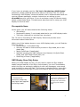
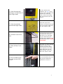
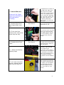
Read this document 2nd
DATA SIGNS
Advanced Sign Technology
www.datasigns.com.au | (03) 9312 2177
VMS Displays
Quick Start Guide
Note: All Signs are shipped with security settings turned off. Find out
more about how to configure the SMS Reporting and Display Optio ns
using the VMS Designer User Manual.
If you have not already read the “So You're Purchasing a VMS Display”
document, please read that document before continuing. The “So You're
Purchasing a VMS Display” document details how to download and install the
various software packages, contains instructions on setting up your
directSMS account, and more. If you do not have a copy of that document,
please contact Data Signs. This document describes how to setup your VMS
display for the first time.
Pre-requisite Items
At this point, you will have obtained the following items:
• SIM card(s).
• Registration plates; if not already attached to your VMS display trailer.
• Two locks (optional) to lock the tires into place.
The “So You're Purchasing a VMS Display” document provides more
information about these items.
Within one of the battery boxes on your VMS display trailer, you will find the
following items:
• A set of keys, in the plastic bag.
• Security bit used to undo security screws on Sign head, also in the
plastic bag .
• Weigh Certificate (if applicable).
• Manuals including the VMS Designer User Manual, this Quick Start
Guide, and SMS Cheat Sheet pack, etc.
• Small bag of fuses (if applicable).
VMS Display Once-Only Setup
When your VMS display arrives, you will need to open the Sign head to
enable various features of the Sign. Unfortunately, you can’t immediately
switch the Sign on and begin updating it with new messages; some steps
must be taken to setup the Sign. This process is detailed below, along with
photos to guide you through. This will only need to be done once per Sign.
Step
1. Remove the
protective-wrap that
may have been applied
to the Sign head.
Photo Illustration
Description
If you use a Stanley knife,
make sure you do not
damage the head while
removing the bubblewrap.
2
2. Undo the security
screw(s) on the front of
your Sign head.
3. Undo the latches
around the Sign head.
4. Lift the Front Cover
Lid.
5. Take off the Cover
Plate.
6. Pull out SIM Cover
Pin and remove SIM
Cover.
Use the Security bit
supplied. The blue arrow
on the photo indicates the
position of a security
screw. There are usually
two screws that must be
undone.
There are up to nine
security screws around the
side of the Sign head that
you will need to undo.
Lift the Front Cover Lid as
far up as you can lift it
and then let it rest back.
The two side struts will
hold the lid in position. For
the following steps, watch
your head!
Now that you have access
inside the Sign head,
remove the Cover Plate.
Pinch together the small
black clips and pull the
Plate forward. There are
about six clips to undo.
Pull out the SIM Cover Pin
and pull the SIM Cover
upwards to remove it.
3
7. Insert SIM card.
Ensure all Pin Codes
have been disabled on
SIM card before
inserting.
`
8. Replace SIM Cover
and insert SIM Cover
Pin.
See above.
11. Attach the Backup
battery plugs.
12. You can now close
the lid , tighten latches
and turn the Sign on.
Don’t put the Main Cover
plate back on yet .
If the Fuses have not been
fitted, you will find them
in a plastic bag in one of
the white battery boxes.
Fit these two Fuses as
shown.
9. Fit the two blue
Fuses (note: one of the
fuses may be red).
10. Replace the Cover
Plate.
To disable all Pin Codes on
the SIM card, place the
SIM card into a mobile
phone and use the phones
menus to complete this.
Then, insert the SIM card
into your Sign. Orient the
SIM card correctly; the
Controller shows the
correct way to insert the
SIM card.
See above.
Fit the Cover Plate back
on each of the small black
clips and push it down to
lock into place.
Normally, only the Red
wire needs to be
connected. These plugs
slide onto the connections
of the battery as shown.
Make sure the Red wire is
connected to the Red
connection on the battery,
etc.
Lift the lid up and then
down again to unlock the
side struts holding the lid
up. Make sure all latches
are tightened and then
use the supplied key to
turn your Sign on (see
below).
4
Switching Your VMS Display On
Step 1
Switch the VMS display on by turning the Key Switch using the key provided.
The location of the Key Switch may vary depending on the type/age of the
VMS display that you are using. Contact Data Signs or your distributor if you
have any queries about this.
Step 2
When your display is switched on, the following text will show on the Startup
screen.
Data Signs
Road VMS
GPS GSM
RADAR
(only if radar has been activated will this line show.)
Following this, the GSM Configuration screen is shown, if a GSM modem is
attached to your VMS display:
LOCATING
GSM NETWORK
If a GSM modem is attached, but the GSM network cannot be found, or you
are outside a service area, your VMS display will then show the following
screen:
NO GSM
SERVICE
DIRECT ONLY
In this case, DIRECT ONLY means that you are only able to update your
VMS display using a direct connection from your PC ; or compatible handheld device. No SMS or remote dial-up functionality will be available.
Step 3
Then, if your VMS display has a message loaded, this message w ill now be
shown, otherwise the screen will remain blank.
5
Setting up Your VMS Display
This section explains how to set up your VMS display once you have driven it
to the desired location. Setting up a VMS Display is not a complex procedure;
however, there are some things that need to be remembered. The most
important advice is: remember to release the Mast Brake before raising
the Sign head into position.
If SMS Reporting and Display Options have been set on your Sign using
the VMS Designer program, s end an SMS to this Sign once it is in place to
reawake the Sign. This also resets the GPS-coordinates of the Sign. More
information about the SMS Reporting and Display Options can be found in the
VMS Designer User Manual available for download from the Data Signs
website.
Step
Photo Illustration
1. Lower the jockey wheel
before disengaging the
tow coupling from the tow
ball of your vehicle. Then,
you can raise or lower the
angle of the Sign head
with the jockey wheel,
depending on the type of
ground the Sign is on.
VMS200 ONLY à
6
2. Pull out the Pin that
holds each of the
Stabilization Legs into
place, and then reinsert
the Pin once the Leg has
been swung out. You can
then wind the Leg up or
down so that the angle of
the Sign head is correct,
and to ensure Sign
stability in windy
conditions.
VMS200 ONLY à
3. Undo the Mast Brake.
This is important! Once the
Mast Brake is undone, you
can then swivel the Sign
head left or right so that
the message can be easily
read by passing traffic.
7
4. Use the Switch located
in one of the battery boxes
to raise the Sign head to an
appropriate level. Then lock
the Mast Brake to hold the
Sign in position.
5. Use the chains on the
trailer to lock the wheels in
place as a preventative
measure against theft.
NOT APPLICIABLE TO
VMS200 Model
6. Remove the tow hitch
and take it away with you.
Some Signs have allowance
for the tow hitch to be
locked onto the Sign itself.
Check your model.
Your Sign has now been
setup!
8
Changing the Message on Your VMS Display
There are a few different methods you can use to change the message
displaying on your VMS Display, such as:
♦ Send an SMS to the Sign from your mobile phone.
♦ Update your Sign directly using the Serial (Local) port on the back of the
Sign head. Do this using the VMS Designer or SMS Designer program.
♦ Use the Data Signs WEB-SEND function if you have an Internet
connection on your PC. The WEB-SEND function is available within the
VMS Designer program.
♦ Dial-up your Sign remotely via a modem attached to your PC. Do this
using the VMS Designer program.
♦ Send an SMS to your Sign using the SMS Designer program, if you have
an Internet connection on your PC.
If you want to display mainly text-based messages on your Sign, the
quickest and easiest way to update your Sign is by sending an SMS to your
Sign from your mobile phone. Use an SMS Cheat Sheet to determine the
format of the SMS message that you need to send to update your Sign.
Alternatively, use the SMS Designer program to send SMS messages to your
Sign from your PC. This program is very easy to use.
If you want to create messages that contain more animation or pictures, use
the VMS Designer program. The VMS Designer software also contains many
other features that may be useful to you. Read the VMS Designer User
Manual for more information.
…via SMS
Since you have already inserted a SIM card into your VMS Display (as
instructed above), changing the message on your VMS Display via SMS is
probably what you will want to do first. You will need to know the mobile
number of your SIM card. The SMS Cheat Sheet describes the various text
formatting codes you may wish to use, however to test SMS enter the
following message into your mobile phone and SMS it to your Sign:
.S123456.3SMS.NTEST
The dots in the SMS message above are important; the letter following each
of the dots is a separate SMS code.
9
VMS Designer and SMS Designer software
If you have not already done so, download and install the software packages
available from the Data Signs website. The manual available with each
software package provides a lot of information about how to update your
Sign with new messages.
Disclaimer
The information contained in this document is proprietary information of
Venetech Pty Ltd t/a Data Signs. Venetech Pty Ltd t/a Data Signs make every
effort to ensure the quality of the information it makes available.
Notwithstanding the foregoing, Venetech Pty Ltd t/a Data Signs does not
make any warranty as to the information contained here in, and does not
accept any liability for any injury, loss or damage of any kind incurred by use
of or reliance upon the information.
Venetech Pty Ltd t/a Data Signs reserve the right to make modifications,
additions and deletions to this document at any time and without notice.
[The latest version of this document is available for download from the Data
Signs website, in PDF format].
The software packages by Venetech Pty Ltd t/a Data Signs (i.e. VMS Designer,
SMS Designer, ArrowStat, etc) have been developed with end-user
interaction and input, and as such we are open to scrutiny, suggestions,
and/or complaints. If unexplained behavior occurs, please send us an email
explaining the problem and the conditions that caused it. Our email address
is: [email protected].
Copyright © Data Signs (Venetech Pty Ltd) 2007
10