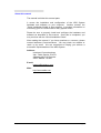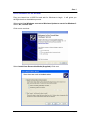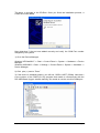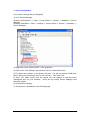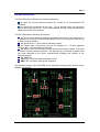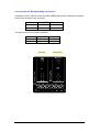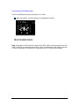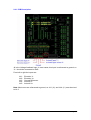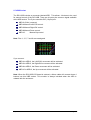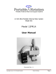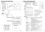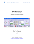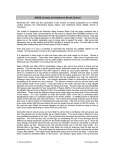
1
Antenna Rotator System
RCI-USB
Reference Manual
September/2011
Rev 1.3c
Introduction
Thank you for purchasing the ARS RCI-USB Interface.
Presently, the ARS System provides the most powerful highest performance and
lowest cost universal rotor interface available anywhere in the world. It can be
connected into any rotor providing 10 bits ADC resolution (2 ^ 10 = 1024 states).
It can work with any “azimuth rotor” or “azimuth & elevation rotor” and a large list of
control and tracking programs are also supported.
Moreover it will convert your rotor into the latest technology automated rotor tracking
system available.
It’s very important that you read this manual carefully. Failure to understand
the contents of the manual could lead to damaging the rotor or the RCI-USB
circuit board through incorrect wiring. Remember that the time you spend reading
the manual and understanding how the system works and how the RCI-USB
board will interface with your rotor could save you time and money by avoiding an
incorrect installation. If any questions occur when reading the manual, please
contact us. Our goal is to provide you will a state of the art antenna tracking
system.
The ARS System has been developed to operate with most rotators available at the
market. If you don't find your rotor mentioned in the Quick Start Guide, again you
should contact us. We will provide assistance to help you successfully connect your
rotor to the RCI-USB circuit board. It is certain that no changes will be required in the
RCI-USB circuit design.
This board is the product of design evolution of previous RCI-SE circuits beginning in
2002. A major enhancement with the current ARS System is the use of a USB port
instead a traditional LPT port.
The board is not powered by the USB port from your computer. It requires a 1214Vdc from a power supply.
When connected to the computer and a 12-14 VDC regulated power supply, and the
proper driver installed, a virtual COM Port will be added to your computer. The RCIUSB firmware will emulate a Yaesu GS232A interface. Any 3rd party program that
supports a Yaesu rotator will be able to control the board.
Additionally, you may use a supplied program called ARSVCOM that will control the
board and allow adjustment and configuration of the RCI-USB product in an attractive
package.
Setup & Hardware Reference Manual: RCI-USB PCB
Page 2
About this manual
The manual is divided into several parts.
It covers the installation and configuration of the ARS System
hardware and software on your computer. Another manual, the
"Quick Installation Guide" is also supplied. It provides information on
connecting your RCI-USB board to many popular rotors.
Please be sure to properly install and configure the hardware and
software as described in this manual. Once this is completed, you
may continue with the “Quick Installation Guide.”
After reading the manual, if you have questions or concerns, please
contact Interlanco Communications. You may check our website or
reach us by email. We are committed to helping you achieve a
successful implementation of the ARS System.
Address:
Interlanco Comunicaciones
Attn:. Pablo García - EA4TX
Albasanz 48-50 4º Derecha
28037 Madrid - SPAIN
E-mail:
[email protected]
Web:
http://www.ea4tx.com
Setup & Hardware Reference Manual: RCI-USB PCB
Page 3
Part 1
Driver Installation for the RCI-USB
Plug your board into a USB Port and wait for Windows to begin. It will guide you
through the driver installation process.
When asked Can Windows connect to Windows Update to search for Windows?
Select, No, not this time.
Click next to continue.
Select Install from Removable Media (Supplied). Click next.
Setup & Hardware Reference Manual: RCI-USB PCB
Page 4
The driver is included in the CD-Rom. Once you finish the installation process, a
COM Port will be added
Now determine if the port was added correctly and verify the COM Port number
assigned by the system:
1) Go to the Device Manager:
Windows XP/Vista/Win7 -> Start -> Control Panel -> System -> Hardware -> Device
Manager
Windows 2000/2003 -> Start -> Settings -> Control Panel -> System -> Hardware ->
Device Manager
2) Click plus (+) next to “Ports”
3) If the device is installed properly, you will see “USB to UART (COMx). Note that x
is the number of the COM Port. Any program that needs to communicate with the
RCI-USB Board (logger, satellite tracking, etc) needs to use the new this COMx port.
Setup & Hardware Reference Manual: RCI-USB PCB
Page 5
1.1 Port reassignment
If you need to change the port assigned:
1) Go to Device Manager:
Windows XP/Vista/Win7 -> Start -> Control Panel -> System -> Hardware -> Device
Manager
Windows 2000/2003 -> Start -> Settings -> Control Panel -> System -> Hardware ->
Device Manager
2) Right click on the “USB to UART.” Click properties.
3) Click on the “Port Settings” tab and then click the “Advanced” button.
4) Pull down the scrollbar on the bottom left side. You will see several COM ports
listed. Select one that doesn't say "in use" next to it. Then click "OK".
5) Click “OK” again. Notice that the device will now appear on the previously
unassigned port you just selected. Verify this by closing Device Manager and
selecting it again.
6) Close device manager.
7) This process is illustrated on the following page.
Setup & Hardware Reference Manual: RCI-USB PCB
Page 6
Setup & Hardware Reference Manual: RCI-USB PCB
Page 7
Part 2
RCI-USB circuit Setup
The RCI-USB circuit fulfils the two following objectives:
It reads the current antenna position by means of an incorporated A/D
converter.
It controls the movement of the rotor. For an azimuth rotor, this would be
right or CW and left or CCW. This is accomplished through relays using the data
obtained from the A/D converter.
The RCI-USB has the following connectors:
J1: The azimuth antenna rotation is controlled by means of this connector. It
is attached to 3 relays on the RCI-USB Board. One of the relays provided (AUX)
is able to control a brake.
J2: Similar than J1, J2 is used for elevation control.
J3: Power input. Connection point for the required 12 - 14 Vdc regulated
power supply. Correct polarity is required.
J4: Input to the A/D converters for the azimuth & elevation rotators. This input
is used to read the antenna position. This point will be connected in parallel with
the wires attached to the rotor’s potentiometer enabling the readout of the
antenna position.
X1: USB Port.
LCD: IDC connector used to attach the LCD.
KBD: IDC connector used by the Keyboard.
The following image is the RCI-USB circuit schematic allowing easy location of the
different connectors:
Setup & Hardware Reference Manual: RCI-USB PCB
Page 8
2.1 Connector J1: Azimuth Relay connections
The RCI-USB has two relays to control the Azimuth movement: right (CW) or left
(CCW). An additional relay (AUX), located between them may be used to control a
brake in rotators requiring a braking function.
These relays are 2 position with 2 circuit switches. Each circuit supports 5A at 220V.
One of the two circuits of each relay is already wired and attached to its connector as
it appears in the following image.
RIGHT relay
AUX relay
LEFT relay
In this manual, the 9 terminals of this connector will be called
J1-1, J1-2,J1-3, J1-4, J1-5, J1-6, J1-7, J1-8 and J1-9.
In de-energised position, J1-2 is switched to J1-1. When it’s activated, J1-2 is
switched to J1-3.
In de-energised position, J1-5 is switched to J1-4. When it’s activated, J1-5 is
switched to J1-6.
In de-energised position, J1-8 is switched to J1-7. When it’s activated, J1-8 is
switched to J1-9.
Right/CW
Relay OFF
J1-2 to J1-1
Relay ON
J1-2 to J1-3
AUX
Left/CCW
J1-5 to J1-4
J1-8 to J1-7
J1-5 to J1-6
J1-8 to J1-9
This first circuit (available at J1) will be used to control movement to the right or left. If
necessary, the second circuit can be used to make a second electric circuit active on
the rotor. It is silk-screen printed on the circuit board. It is next to the relays and
identified with the following references:
ABC
DEF
GHI
Setup & Hardware Reference Manual: RCI-USB PCB
Page 9
Switching is similar to J1. The de-energised positions are:
B to A
E to D
H to G
And the energised positions remain switched:
B to C
E to F
H to I
Right/CW
AUX
Left/CCW
Relay OFF
B-A
E-D
H-G
Setup & Hardware Reference Manual: RCI-USB PCB
Relay ON
B-C
E-F
H-I
Page 10
2.2 Connector J2: Elevation Relay connections
In addition to the 3 azimuth relays, the RCI-USB Board includes 2 relays for elevation
control if an elevation rotor is present.
UP
Relay OFF
J2-2 to J2-1
Relay ON
J2-2 to J2-3
Down
J2-5 to J1-4
J2-5 to J2-6
The extra second circuit is also available:
UP
DOWN
Relay OFF
2’ - 1’
5´ - 4´
Up relay
Setup & Hardware Reference Manual: RCI-USB PCB
Relay ON
2´- 3´
5´ - 6´
Down relay
Page 11
2.3 Connector J3: Power input
The RCI-USB Board must be powered at 12-14 Vdc.
Note the polarity. Incorrect polarity can damage the board.
J3-1 is the positive terminal.
J3-2 is the negative terminal.
Note: Although the CPU and some parts of the RCI-USB could be powered from the
USB, it requires an external power supply. Some components as the replays requires
a 12Vdc. Remember to connect this J3 terminal into a 12-14Vdc power supply.
Setup & Hardware Reference Manual: RCI-USB PCB
Page 12
2.4 Connectors J4: Operation of the ADC
The Analog-to-Digital converter (ADC) allows the computer to determine the direction
the rotor and antenna are pointing. To enable, connect the two wires attached to the
azimuth (or elev.) rotator’s potentiometer to J4.
Most rotors use a similar system to read the position in the control unit. The
illustration below offers an overview of this operation:
Potentiometer ≈ 500Ohms
Control Unit
V
Cable to the
Rotator
N
ROTATOR
S
<
>
Inside the rotator there is a potentiometer engaged with the antenna mast axis. The
voltage feedback changes when the antenna is turned. The existent voltage will
change at both ends of the rotation cycle. Normally this will be 0 V at one end
(CCW). The other end will show the maximum value in the rotation cycle. It will be
called “V”. This value depends on each model of rotator optimized for a specific rotor
by the manufacturer. A 500 Ohms linear potentiometer is normally used.
As examples, voltage “V” in a HAM-IV rotor is 12V, in the Kenpro KR-600RC or
YAESU G-2000 it is -3.6V. In some rotors the value is 5V. Again this depends on the
individual rotor.
It is very important to know the voltage “V” provided by your rotator. This
voltage V may not be specified in the manufacturer’s documentation so it
must be checked with a voltmeter for correct operation of the ARS System. If
the Pot is Grounded, you can connect the “V-“ Input at J4 (J4-4 for Azimuth
and J4-1 for Elevation) to Ground at J4-3.
As the RCI-USB board must obtain the voltage feedback from the external Pot, the
two wires that join the control unit with the rotator (the one from the cursor of the
potentiometer and the other from the ground or reference) must be connected in
parallel with the J4 terminals (J4-4 & J4-5). Remember that J4-1 & J4-2 are only
used in elevation rotators.
By this method, the RCI-USB board can read the voltage present at the rotator
potentiometer and thus calculate the beam direction.
The A/D converter has 10 bits resolution. This equates to 1024 possible values. For
example, if the maximum rotation is 360 degrees, a positional resolution of 0.35
degrees is possible. This capability will be more than adequate for most applications.
Setup & Hardware Reference Manual: RCI-USB PCB
Page 13
Unfortunately as previously discussed, not all rotors have a standard voltage value
for V. The A/D converter accepts 5V as maximum voltage. To obtain the maximum
digital output level, the signal from the rotor will have to either be attenuated or
amplified. Again this will depend on the individual rotor.
In the previous example we found that a HAM-IV or T2X rotator gives 12V when it is
fully turned clockwise (CW limit). Therefore voltage from the rotor will have to be
attenuated to 5 V by adjusting Pot1.
In other examples mentioned, rotators like the Kenpro KR-600RC or YAESU G-2000
may show a maximum voltage that is negative (-3.6V). Therefore the signal to the
RCI-USB board will have to be amplified to avoid losing resolution in the converter.
Polarity will also change from negative to positive. The is also accomplished by
adjusting the gain at Pot1.
The RCI-USB has a potentiometer for each input providing all of these adjustments:
Azimuth input:
Pot1 adjusts the Gain/Attenuation between 3-24V.
Elevation input:
Pot2 adjusts the Gain/Attenuation between 3-24V.
Even though your rotator may appear in Part 3 in this manual, it is highly
recommended that you check the data with your own rotor by means of a voltmeter.
The insertion of the RCI-USB in parallel between the Rotor and the
Control Unit should not cause any error or modification in the readout of the
original instrument. The RCI-USB circuit presents high impedance at the J4
input.
Setup & Hardware Reference Manual: RCI-USB PCB
Page 14
The following illustration shows the correct Rotator + Control Unit + RCI-USB wiring :
Potentiometer ≈ 500OhΩ
Control Unit
ROTATOR
N
S
<
>
RCI-USB
J4
You can find the two wires by looking at the circuit diagram included with the rotator.
Be very careful with the polarity! J4-4 is the negative input or reference
connection and J4-5 is the cursor of the potentiometer. It is important that you check
the actual voltage at these points with a voltmeter. This can be achieved by turning
the antenna from one end to the other and writing down all the voltage readings at
both ends. You should also observe that the voltage increases or decreases between
its ends while the rotator and antenna are turning. Remember that one end will
correspond to 0V and the other to the maximum voltage “V”.
Note: If you Potentiometer rotor is grounded it’s highly recommended to connect
the V- input (J4-4) to the RCI-USB ground (J4-3).
Azimuth Calibration:
Move the Azimuth rotor to the CW limit (right limit). Check the voltage at X2 pin #1.
The X2-ADC pin #1 is located close to the 40 pin IC close to C13. It is the ADC
analog Azimuth Input of the µController. Adjust Pot1 until you obtain a reading of
5.0V. When Pot1 is moved CW, the signal input will be attenuated. When it’s moved
CCW, it will be amplified.
Elevation Calibration:
Similar to the azimuth calibration, elevation calibration is accomplished by a similar
process at X2 pin #3 (close to C14).
Note: Instead of using a voltmeter connected at X2 pin #1 and pin #3, you can use
the calibration function in the software for making the Pot1 or Pot2 adjustments.
Setup & Hardware Reference Manual: RCI-USB PCB
Page 15
2.4.1 PCB Description
J4 is the Voltage feedback Input. In most cases, this Input is referenced to ground, so
“V-“ should be connected to GND.
From left to right the inputs are:
J4-1:
J4-2:
J4-3:
J4-4:
J4-5:
Elevation VElevation V+
Ground Reference
Azimuth VAzimuth V+
Note: Most rotors are referenced to ground, so J4-1 (V-) and J4-4 (V-) must be wired
to J4-3.
Setup & Hardware Reference Manual: RCI-USB PCB
Page 16
When positive the Voltage feedback that the external rotor provides will be connected
to the V+ input. The reference voltage that normally is Ground will be connected to
the V- input. Remember that most rotors are referenced to a real ground and it is
highly recommended to connect the V- input to the Ground reference.
Example for Azimuth rotors referenced to Ground:
Positive Potentiometer Feedback ──────► J4-5
Negative Potentiometer Feedback ─────► J4-4
If the Negative is referenced to Ground, connect J4-4 to J4-3.
Once connected, there is a Pot that can be adjusted for correct input to the RCI-USB
ADC input:
Azimuth Input Adjustment:
•
POT1: will adjust the Gain of the Amplifier. CCW movement will attenuate the
input voltage while CW movement will increase the input voltage. You can
additionally use the ARSVCOM software calibration procedure to read the
maximum ADC value. While doing this, use a screwdriver to adjust POT1. Of
course you can place a voltmeter at point X2-1, and adjust the POT1 in the
same manner until the voltmeter displays 5V. This adjustment must be done
when the rotor is placed at the CW (Right limit).
Elevation Input Adjustment:
•
POT2: The procedure to calibrate the Elevation Gain at POT2 is the same as
the Azimuth calibration with POT1.
Setup & Hardware Reference Manual: RCI-USB PCB
Page 17
2.5 X1 Point, Led point
The RCI-USB includes at the X1 connector, a check point for each relay:
-
Left, Aux and Right
-
Down and Up
The pins available at the X1 socket can be connected with 5 Led’s. However a 470
Ohms resistor must be inserted. Those points will supply 0V when not activated and
5V when each pin is activated.
The common point for each Led is wired with the ground at the RCI-USB PCB.
X1 Pin assignment:
X1-1:
X1-2:
X1-3:
X1-4:
X1-5:
X1-6:
GND
Up relay
Down relay
CW/Right relay
Aux relay
CW/Left relay
Setup & Hardware Reference Manual: RCI-USB PCB
Page 18
2.6 LCD Socket and contrast adjustment
The RCI-USB can handle a 16x2 LCD display.
This connector is used to attach the LCD module to the RCI-USB.
VR1 can be used to adjust the LCD contrast.
☛
There is an optional PCB that you can order with the unit. This RCI-USB LCD
supports a 16x2 LCD and 4 bush buttons. This module is always included when
the ARS is ordered with the enclosure.
Optional RCI-USB LCD board
Setup & Hardware Reference Manual: RCI-USB PCB
Page 19
2.7 KBD Socket
The RCI-USB includes a connector labeled KBD. This allows 4 buttons to be used
for manual control of the RCI-USB. There are 4 inputs plus common signal available
at the KBD socket. The 5 pins used this IDC (10 pins) are:
KBD-2: +5Vdc (common)
KBD-4: Manual Left/CCW control.
KBD-6: Manual Right/CW control.
KBD-8: Manual Down control.
KBD-10:
Manual Up control.
Note: Pins 1, 3, 5, 7 and 9 are unassigned.
If you connect:
KBD-4 to KBD-2, the Left/CCW movement will be activated.
KBD-6 to KBD-2, the Right/CW movement will be activated.
KBD-8 to KBD-2, the Down movement will be activated.
KBD-10 to KBD-2, the Up movement will be activated.
Note: When the RCI-USB LCD board is ordered, a ribbon cable will connect those 4
buttons into this KBD socket. This module is always included when the ARS is
ordered with the enclosure.
Setup & Hardware Reference Manual: RCI-USB PCB
Page 20
Part 3
Working with the RCI-USB
Once you have wired the RCI-USB board with your rotor and the driver is installed,
now you can begin to control the interface.
There are 2 ways you can interact with the product:
•
COM Port: this port is automatically created each time the PC detect the RCIUSB
•
4 Keypad: F1, F2, F3 & F4
3.1 COM Port:
Via the COM port the user or a 3rd part program can send and receive commands
to/from the RCI-USB.
The manual: “RCI-USB Commands” describe all commands that are supported.
Some of them are commands for configuring and calibrate the interface. Some other
are used for controlling the appointing. Basically a satellite tracking program or a
logging program will use only those commands for control the appointing.
IMPORTANT NOTE:
The RCI-USB emulates a Yaesu GS232A interface, so any
program that supports this tracker interface with work with it.
3.2 Keypad: F1, F2, F3 & F4
If you have ordered the RCI-USB LCD optional PCB, you have an additional board
with a 16x2 LCD and 4 buttons, that are labeled as:
•
F1: Which control the Left/CCW movement
•
F2: Which control the Right/CW movement
•
F3: Which control the Up movement
•
F4: Which control the Down movement
So pressing those buttons you can control manually the motors.
If you own an “Azimuth” model, the Up/Down buttons are not required, so in this
case, those buttons are assigned as “PRESET” control.
So pressing F3/F4 you can change the preset and after a idle period, the RCI-USB
will start the appointing into that preset value.
Remember that you can cancel an appointing at any time, just press F1 or F2, and it
will stop.
Setup & Hardware Reference Manual: RCI-USB PCB
Page 21
3.3 Special Keypad options
If some buttons (individual or combined) are pressed meanwhile the RCI-USB is
energized, we can get some extra functions.
A.- Bootloader – F1
Some time ago, the only option for upgrade a microcontroller with a new firmware
(code) was to request a new chip from the manufacturer. As you can imagine this is a
slow and expensive method. A bootloader is an option for loading a new firmware
into the microcontroller and the RCI-USB includes it.
You can enabled the bootloader code, by pressing F1 button during the power on.
So, as simple as pressing F1 and power on the RCI-USB. Immediately you can
release F1. The bootloader will be enabled.
Now you need a program that helps you to send the new firmware (hex file) into the
microcontroller. You can use Hyperterminal (send the firmware as a text file) or use
the RCI_Load program, included on the CD-ROM. So locate inside the CD-ROM the
directory Teleloader, and run the setup.exe, and the RCI_Load will be installed on
your computer.
B.- Absolute Mode – F2
The Absolute mode is enabled if F2 button is pressed during the power on of the
RCI-USB.
The absolute mode allows to:
•
Disabled the watchdog limits
•
Display on the LCD the ADC value (0-1022)
By default, the RCI-USB includes a watchdog and if it detects that the rotator has
reach one of their limits (CCW/Left or CW/Right on Azimuth; Up or Down on
Elevation) the relay which control the movement in that direction is disabled. Imagine
that the RCI-USB reads ADC = 0, so it suppose that the motor is at the CCW/Left
limit. So the CCW Relay will be disabled.
The Absolute mode disables this feature, so you can move any relay.
This option is useful when you have done a wrong calibration and you don’t want a
factory default configuration.
C.- Factory default configuration – F3 + F4
If you want to load the default configuration, you must press F3 and F4 (both buttons
at the same time) and power on the unit.
Immediately the default configuration will be restore.
Setup & Hardware Reference Manual: RCI-USB PCB
Page 22
Specifications
J1: AZIMUTH RELAY CONNECTOR
3 x Relay: 2 circuits, 5A at 220V.
J2: ELEVATION RELAY CONNECTOR
2 x Relay: 2 circuits, 5A at 220V.
J3: POWER CONNECTOR
Input voltage:
Power consumption
(Standby):
Power consumption
with relays switched on :
12-14V
<200mA with LCD or < 110mA w/o LCD
<250mA with LCD or < 160mA w/o LCD
J4 INPUTS
J4-5 & J4-4 are the azimuth rotor feedback input. It is adjusted by means of Pot1
(Gain control).
J4-2 & J4-1 are the elevation rotor feedback input. It is adjusted by means of Pot2
(Gain control) .
Input signals between +/-3 to +/--24V can be regulated by means of Pot1 or Pot2.
CONNECTOR X1:
USB socket.
CIRCUIT DIMENSIONS
12cm x 12cm x 3,5cm
4.7inch x 4.7inch x .8inch
(Deep, Wide, High)
(Deep, Wide, High)
Setup & Hardware Reference Manual: RCI-USB PCB
Page 23
Notes
[The remainder of this page has been left intentionally blank]
Setup & Hardware Reference Manual: RCI-USB PCB
Page 24
Index
Introduction .................................................................................................... 2
About this manual ......................................................................................... 3
Driver Installation for the RCI-USB............................................................... 4
1.1 Port reassignment................................................................................... 6
RCI-USB circuit Setup ................................................................................... 8
2.1 Connector J1: Azimuth Relay connections.............................................. 9
2.2 Connector J2: Elevation Relay connections.......................................... 11
2.3 Connector J3: Power input.................................................................... 12
2.4 Connectors J4: Operation of the ADC................................................... 13
2.4.1 PCB Description................................................................................. 16
2.5 X1 Point, Led point................................................................................ 18
2.6 LCD Socket and contrast adjustment.................................................... 19
2.7 KBD Socket........................................................................................... 20
Working with the RCI-USB .......................................................................... 21
3.1 COM Port: ............................................................................................. 21
3.2 Keypad: F1, F2, F3 & F4....................................................................... 21
3.3 Special Keypad options......................................................................... 22
A.- Bootloader – F1 ....................................................................................... 22
B.- Absolute Mode – F2.................................................................................. 22
C.- Factory default configuration – F3 + F4 ......................................................... 22
Specifications............................................................................................... 23
Notes............................................................................................................. 24
Index ............................................................................................................. 25
Setup & Hardware Reference Manual: RCI-USB PCB
Page 25