1
Ramsey Electronics Model No.
ad
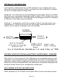
BATTERY CONDITIONER/
RAPID CHARGER
NiC
Dr. NiCad
Dr.Nicad is your best
Rx for nicad batteries!
DN1
Stop shelling out a fortune on batteries ! Enjoy full performance
from your NiCad batteries or battery packs with this sensational
•
Quick charges batteries for laptop computers, hand-held radios
and scanners, cordless/cellular phones, camcorders, RC models
and more ! Charge many batteries in less than an hour !
•
State-of-the-art battery monitor IC safely watches both battery
voltage and charge time while fast charging your batteries !
•
Eliminate “Memory Effect” common to NiCads - uses unique
constant current circuitry.
•
Safety First: circuit has “built in” timers and voltage sensors that
monitor the cell for safety - it won’t let you charge a bad cell !
•
Stop “cooking” and start conditioning your rechargeable batteries,
no more leaving the charger plugged in for days on end !
•
Charges single cells as well as NiCad packs from 1 to 10 cells !
•
Automatic “top off” charge keeps batteries at their peak power until
use.
•
Unit runs on 12-15 volts DC.
•
Convenient flashing LED indicates charging modes and eliminates
guesswork.
DN1 • 1
RAMSEY TRANSMITTER KITS
· FM10A FM25B FM Stereo Transmitters
· FM100B Professional Quality FM Stereo Transmitter
· TV6 Television Transmitter
· AM1, AM25 AM Transmitters
RAMSEY RECEIVER KITS
· FR1 FM Broadcast Receiver
· AR1 Aircraft Band Receiver
· SR2 Shortwave Receiver
· AA7 Active Antenna
· SC1 Shortwave Converter
RAMSEY HOBBY KITS
· SG7 Personal Speed Radar
· SS70 Speech Scrambler
· TT1 Telephone Recorder
· SP1 Speakerphone
· MD3 Microwave Motion Detector
· PH10 Peak hold Meter
· LC1 Inductance-Capacitance Meter
RAMSEY AMATEUR RADIO KITS
· DDF1 Doppler Direction Finder
· HR Series HF All Mode Receivers
· QRP Series HF CW Transmitters
· CW7 Keyer
· QRP Power Amplifiers
RAMSEY MINI-KITS
Many other kits are available for hobby, school, Scouts and just plain FUN. New
kits are always under development. Write or call for our free Ramsey catalog.
DOCTOR NiCad BATTERY CONDITIONER KIT INSTRUCTION MANUAL
Ramsey Electronics publication No. MDN1 Revision 1.1a
First printing: March, 1994
COPYRIGHT ã1994 by Ramsey Electronics, Inc. 590 Fishers Station Drive, Victor, New York
14564. All rights reserved. No portion of this publication may be copied or duplicated without the
written permission of Ramsey Electronics, Inc. Printed in the United States of America.
DN1• 2
Ramsey Publication No. MDN1
Price $5.00
KIT ASSEMBLY
AND INSTRUCTION MANUAL FOR
Dr. NiCad
NiCad BATTERY
CHARGER/CONDITIONER
TABLE OF CONTENTS
Introduction to the DN1 ................. 4
How it works.................................. 6
Parts list ........................................ 8
Schematic diagram ....................... 9
Parts Layout diagram .................. 11
DN1 Assembly instructions ......... 12
Setup configurations .................... 16
Troubleshooting ........................... 21
Ramsey kit warranty .................... 23
RAMSEY ELECTRONICS, INC.
590 Fishers Station Drive
Victor, New York 14564
Phone (585) 924-4560
Fax (585) 924-4555
www.ramseykits.com
DN1 • 3
INTRODUCTION
With today’s ever changing technologies, more appliances depend on battery
power to enable their use. While this gives us greater freedom, it is often at
the high cost of purchasing portable energy, or batteries, to run our portable
electronic gismos. Consider the cost of energy from our local electric
company, about 8¢ for a KW hour, or about 450,000 joules of energy for a
penny. On the other hand, that 500 mA-H NiCad that you just purchased for
about $1.75 can only supply 2250 joules of energy; that's about 13 joules for
1 cent. So it’s fairly easy to see that energy costs about 35,000 times more
when it’s in a battery.
Nobody likes the idea of throwing all those batteries into a landfill. That's the
reason for the recent emphasis on using “green” rechargeable cells. If a set
of NiCad cells lasts you for a few months, they can save the equivalent
volume of themselves many tens or hundred times in the trash. This is not
only good for the environment, it’s also great for the wallet!
Nicad rechargeable batteries have been around for years, but there are a few
real disadvantages in their use. They usually require a long time (sixteen
hours) to recharge. This “trickle charge” arrangement is quite common
because it is much cheaper for the original product manufacturer to produce
(the entire battery charger is typically a couple of rectifier diodes and a
current limiting resistor), and works well given the draw back of a long charge
time.
Another disadvantage to the “plug-in wall transformer charger” is that the
charging cutoff action is regulated by the heat produced by the cells’
chemical reaction when recharging. If you’ve ever opened up a rechargeable
pack you have probably seen the thermal shutoff “mystery part” connected
and mechanically touching one cell of the battery pack. While this will help if
you leave your appliance charging for several days, notice that it is sampling
only one cell in the pack, and assuming that the rest of the batteries are
“behaving” in the the same manner. Also, since the ambient temperature can
change (i.e.recharging your cordless drill in the cool garage or basement, or
your two way radio on the hot seat in the car), this heat sensing approach
can vary considerably from undercharging your pack to overcharging until
you “cook” the electrolyte solution right out of the battery.
Often times we cannot wait for the full recommended charging time or do not
use the batteries until they’re completely “dead”. When this is repeated, the
uncared for battery or pack can seem to “run out” rather quickly. This effect is
caused by not completely discharging the cell before it is recharged and is
known as the memory effect, since the battery appears to memorize the
amount of energy it is called upon to produce.. By not completing the
DN1• 4
oxidation reduction or “redox" chemical reaction in the cell, we effectively
decrease the chemically active surface area inside the cell. The lower this
surface area, the shorter the battery’s life. Since you don’t try to recharge
conventional batteries, you’ve never noticed this property until you started to
use rechargeable NiCad batteries.
To keep your cells working like new and to eliminate this memory effect, we’ve
built in an automatic discharge circuit that will properly discharge the cells
before their recharging.
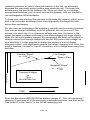
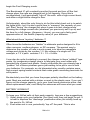
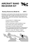
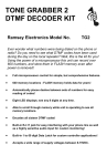
So, you can see recharging a NiCad battery correctly can be a tricky business.
How can we charge the battery to its full potential, but not too much? The
answer is to watch the ∆V or change in voltage over time. As shown in the
graph, the battery voltage continues to rise while charging but drops slightly
when the cell is completely charged. By recognizing this point on the graph, a
charger can put just enough charge into the cell. By virtue of this voltage -vstime checking, it is also possible to charge the battery at a much higher
charging current - and significantly reduce the battery charging time. Once this
point is reached, it is best to “top off” the battery with a charge burst every now
and then.
Full Charge
Positive "Slope"
or + dV
dT
Slope = Zero
VOLTAGE
Negative "Slope"
or - dV
dT
Terminal Voltage
vs
Time
for a NiCad Cell
TIME
Enter the Benchmarq BQ2003 NiCad battery charger IC. This cell monitoring /
charging IC performs all of the previously mentioned functions, and then some.
This smart IC is the “doctor” in our NiCad recharging unit.
DN1 • 5
We designed our kit to change quickly and easily adapt to a variety of cell or
battery pack types for anything from video camcorders to cordless phones.
You can configure it for the number of batteries in your pack, discharge and
charging rate. We’ll discuss this later as we’re assembling these sections of
the circuit.
DN1 CIRCUIT DESCRIPTION
Before we get into the technical jargon, let’s take a walk around the BQ2003
Integrated Circuit . We’ll start with some definitions of the abbreviations
written on the chip in the schematic diagram.
Benchmark BQ2003 pin designations:
Pin No.
Abbreviation
Function
1
CCMD
Charge command
2
DCMD
Discharge Before Charge Command
3
DVEN
- ∆V Enable Input
TM1 & 2
Timer Mode Outputs
7
BAT
Single Cell Voltage Input
8
VSS
Ground
9
SNS
Charging Current Sense Input
11
MCV
Maximum Cell Voltage Reference
13
CHG
Charging Status LED Output
14
MOD
Current Switching Control Output
15
DIS
Discharge Control Output
16
VCC
5 Volt input
4,5
The BQ2003 charger IC handles many of the functions related to our
charger. Without trying to sound too much like a technical manual or data
book, here’s a closer look at some of the accompanying circuitry. Have a
glance at the schematic diagram and follow along.
DN1• 6
Since we want the voltage appearing at the IC to be equivalent to one cell,
we first must “divide” the cell voltage by the number of cells in the pack.
The ladder resistors R2 -R24 form an effective voltage divider circuit so that
the BAT (pin 7) voltage will be about 1.25 V per cell. The switch can increase
or decrease the BAT voltage by adding or subtracting “rungs” from the
voltage divider ladder. Another divider network consists of resistors R14 and
R16. This voltage sets up the MCV voltage for the BQ2003 IC. This should
measure 1.8 V when in operation.
Seeing how you’ll want to charge your batteries quickly, you need a high
charging current power supply to back you up. Transistors Q2, Q1, and
components D1 and L1 form the “high current” portion of our “switchedmode-regulator” circuit. When the MOD output goes “high”, transistor Q2 is
turned on, like a switch. This current then flows into the battery. Resistor R29
(and/or R27) is in series with the current flow and the voltage drop across it
is sensed by IC pin 9, the sense pin. When the sense pin reaches its trigger
point, the transistor is abruptly turned off. When this occurs, the magnetic
field around the coil quickly collapses and causes a reverse voltage “spike”
which is routed through the “catch” diode D1. This energy is recovered and
delivered to the battery cells being charged. This is what provides us with the
high current to quickly charge the cell, but does not dissipate power in the
FET or NPN transistor, making the switched power much more efficient than
a conventional pass transistor type of supply. Another contributing factor to
the charging circuit is the charge rate setup, which is configured using
resistors R26 and 27, as well as test points A - F.
Transistor Q3 is the integral part of our constant current discharging circuit.
When the chip sees a positive going pulse at the DCMD pin, it initiates the
DIS discharge output. With switch S1:10 closed diodes D2 and D4 are
forward biased, causing 1.4VDC to be present at the base of Q3. With 1.4 V
at the base, there is .7 VDC at the emitter, a diode drop in potential lost
through the transistor. With the emitter at .7 VDC, the current through
resistors R10 and R22 is about 140 mA, regardless of the cell voltages. If
switch S1:10 is opened the potential increases to 1.4 VDC. increasing the
current to 280 mA. This will continue to discharge the batteries until they
reach a potential of about .9 volts per cell. The Benchmarq chip then initiates
its own charging sequence.
A few final points concerning the TM1 and TM2 time-out, which are
configured using points G - J. They are dependant on the charge capacity, or
“C” of the pack. We’ll discuss this in more detail when it comes time to
configure these jumpers.
DN1 • 7
DN1 PARTS LIST
RESISTORS
1
2
3
2
4
2
1
1
11
270 ohm [red-violet-brown] (R12)
.5 ohm ½ Watt [green-black-silver] (R26, 27)
10 ohm [brown-black-black] (R 2, 10, 22)
470 ohm [yellow-violet-brown] (R3, 7)
1K ohm [brown-black-red] (R1, 5, 9, 25)
10K ohm [brown-black-orange] (R11, 20)
10K ohm 1% [brown-black-black-red] (R16)
17.8K ohm 1% [brown-violet-grey-red] (R14)
47K ohm resistors [yellow-violet-orange] (R4,6,8,13,15,17,18,19,21,
23, 24)
CAPACITORS
3
3
1uF electrolytic capacitors (C1,C3,C3A)
10 uF electrolytic capacitors (C2, 5, 6)
INDUCTORS
1
Axial lead inductor [enameled wire wound on ferrite core] (L1)
SEMICONDUCTORS AND INTEGRATED CIRCUITS
3
2
1
1
1
1
1
1
1
1N4148 diodes [glass case with black band] (D2, 4, 7)
1N4002 diode [epoxy case marked 1N4002] (D5, 6)
1N4937 fast recovery diode [ epoxy case marked 1N4937] (D1)
Light Emitting Diode [LED] (D3)
NPN small signal transistor [2N3904 or equivalent] (Q2)
NPN power type [marked TIP31C] (Q3)
Power FET [marked 7035] (Q1)
78L05 voltage regulator [marked 78L05] (VR1)
BQ2003 16 pin IC (U1)
MISCELLANEOUS PARTS AND HARDWARE
1
1
2
1
1
2
1
1
2.5mm power jack (J3)
10 position DIP switch (S1)
DPDT pushbutton switch (S2, 3)
DN1 printed circuit board
TO-220 heatsink (HS1)
#4-40 screws and nuts
Insulated jumper wire
6” piece of two conductive wire (blk, red)
DN1• 8
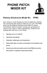
DN1 • 9
RAMSEY Learn-As-You-Build KIT ASSEMBLY
There are numerous solder connections on the DN1 printed circuit board.
Therefore, PLEASE take us seriously when we say that good soldering is
essential to the proper operation of your Doctor Nicad!
•
•
•
•
Use a 25-watt soldering pencil with a clean, sharp tip.
Use only rosin-core solder intended for electronics use.
Use bright lighting. A magnifying lamp or bench-style magnifier may
be helpful.
Do your work in stages, taking breaks to check your work. Carefully
brush away wire cuttings so they don't lodge between solder
connections.
We have a two-fold "strategy" for the order of the following kit assembly
steps. First, we install parts in physical relationship to each other, so there's
minimal chance of inserting wires into wrong holes. Second, whenever
possible, we install in an order that fits our "Learn-As-You Build" kit building
philosophy. This entails describing the circuit that you are building, instead of
just blindly installing components. We hope that this will not only make
assembly of our kits easier, but help you to understand the circuit you’re
constructing.
For each part, our word "Install" always means these steps:
1. Pick the correct part value to start with.
2. Insert it into the correct PC board location.
3. Orient it correctly, follow the PC board drawing and the written
directions for all parts - especially when there's a right way
and a wrong way to solder it in. (Diode bands, electrolytic
capacitor polarity, transistor shapes, dotted or notched ends
of IC's, and so forth.)
4. Solder all connections unless directed otherwise. Use enough
heat and solder flow for clean, shiny, completed connections.
Now, let's get building!
Since you may appreciate some “warm-up” soldering practice as well as a
chance to put some “landmarks” on the PC board, we’ll first install some
“hardware” components. This will also help us to get acquainted with the up down, left - right orientation of the circuit board. Remember that the
components will be mounted on the “component” side of the circuit board
and soldered on the “solder” side of the circuit board.
DN1• 10
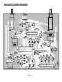
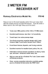
DN1 PARTS FINDER DIAGRAM
DN1 • 11
1. Identify and install DPDT switch S2. Be sure to push the switches flat
to the circuit board. Solder all six connections.
2. Install the other DPDT toggle power switch S3. Once again, be sure to
push the component flush to the circuit board before soldering.
We’ll start our “learn-as-you build” instructions with the power supply section
of the circuit.
3. Install the 2.5 mm power connector in the J3 position.
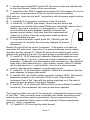
4. Install D6, a 1N4002 type diode. Notice that one end of this
component is marked with a band. Diodes are “polarized”, that is, like a
battery, they have a positive (+) and negative (-) side. Be
sure to follow the parts diagram carefully and orient the
banded end as shown. Note also that this component will
“stand up” in place. Form the component leads as shown
before installing the part.
5. In the same manner, install diode D5, 1N4002 type. Be
sure to orient it correctly! See the parts diagram for correct
placement.
Diodes D5 and D6 act as circuit “protection”. If the power is hooked up
incorrectly D6 acts as an “open circuit” to prevent damage to the voltage
regulator and the charger IC. Diode D5 prevents the battery pack under
charge from powering the unit if the input power is accidentally removed.
6. Install C5, 10 uF electrolytic capacitor. Electrolytic capacitors are
polarized with a (+) and a (-) lead and must be installed in the correct
orientation. Ordinarily, only the negative side is marked on the capacitor
body with a dark band and the (-) sign clearly shown, while PC boards
will usually show the (+) hole location. Use care to ensure proper
polarity. See the parts diagram for proper placement.
7. Install C6, 10 uF electrolytic capacitor. Watch the orientation! See the
parts diagram for proper placement.
8. Identify VR1, the 78L05 voltage regulator (marked 7805). This device
produces a stable 5 volt reference for the circuit. Notice that this
component has a “flat” side with the writing imprinted on it. Be sure to
place the part as shown in the parts diagram.
9. Install C2, 10 uF electrolytic.Observe the correct polarity! If installed
incorrectly, this component can heat up and even explode!
That wasn’t so bad, now was it! You have just completed the power section
of your DN1. Take a moment now to recheck your solder connections and
touch up any less than perfect connections. Have a second look at the
component polarities in this section as the majority of these components
have a (+) and (-) orientation.
10. Install R3, 470 ohm [yellow-violet-brown].
DN1• 12
11. Install R1, 1K ohm [brown-black-red].
11. Install Q1, the power FET transistor [marked 7035]. Form the leads
as shown prior to
installation. Bolt the
Power FET
regulator to the circuit
Tab
board.
12. Install L1, the large
axial leaded wire wound
inductor.
Solder Connections
13. Install D1, 1N4937 fast
recovery diode. Observe the correct polarity! Note also that this is
another “stand up” diode, so form the leads as before for a proper fit.
14. Identify Q2, a 2N3904 NPN transistor. When installing Q2, observe
correct placement of the flat side. Press the transistor snugly into the
PC board so that only a minimum amount of wire lead is exposed above
the board. In soldering, do not be afraid of using enough heat to make a
good solid connection.
15. Install R9, 1K ohm [brown-black-red].
That’s it for the switching high current supply! This part of the circuit provides
the “muscle” to charge the batteries.
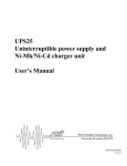
16. Install LED D3. This component is polarized and must be oriented
correctly. Examine the LED and notice how one lead is longer than the
other. Most diodes also have a flat mold in one side of the component
body. This flat side is on the same side as the shorter leg. When
properly installed, the flat side should face towards S2. Leave the diode
leads as long as possible, because this component will mount to the
front panel as a charging status indicator.
LED
Leave these leads
as long as possible
(-)
PC Board
(+)
17. Using scrap component lead, form a “jumper” wire and install it in the
JMP2 position. A jumper acts as an electronic bridge to carry power and
signal over the traces run underneath.
18. Form and install another jumper, JMP1.
19. Install R7, 470 ohm [yellow-violet-brown].
20. Install R12, 270 ohm [red-violet-brown].
21. Install R14, 17.8K ohm 1% [brown-violet-grey-red].
22. Install R16, 10K ohm 1% [brown-black-black-red].
DN1 • 13
23. Select two of the 1uF electrolytic capacitors and solder the ground
leads together.Install them as C3. Bend the ground leads away from U1.
24. Install C1, the remaining 1uF capacitor. The positive side should be
facing R5.
25. Install the Benchmark BQ2003 IC. Notice that one end of the chip is
marked with a dot, notch, or band. Be sure to orient this end as shown in
the parts diagram. Pin 1 is located directly below the notch when the IC
is positioned so that the notch is to the left. If you prefer to use an IC
socket, you may install one if you wish. Be aware, however, that our
techs find more repair problems due to sockets than due to chips burned
out from overheating with a soldering iron. Be extra careful not to
“bridge” the printed circuit traces together.
25a. On the bottom side of the board, install a short piece of insulated
wire between pins 1 and 8 of U1. Be sure to select the right pins.
26. Install R5, 1K ohm [brown-black-red].
27. Install transistor Q3, the
NPN Power
NPN power type. When
Heat Sink
installing, be sure to form the
Tab
leads as shown to allow an
easy fit. Usually it is easier to
mechanically mount the
component with its heatsink
and then solder the
connections. Install the screw through the heat sink and the component.
Tighten the nut securely.
28. Install D2, 1N4148 type diode [glass case with dark band]. Be sure to
orient the banded end as shown in the parts diagram.
29. Install D4, 1N4148 diode. Watch that polarity! See the parts diagram
for proper placement.
30. Install R22, 10 ohm [brown-black-black].
31. Install R10, also 10 ohm [brown-black-black].
32. Install D7, 1N4148 diode [glass case with dark band]. Be sure to
observe the correct polarity.
You’ve just completed the constant current battery discharging portion of the
circuit. This section, when initiated, will discharge the battery at a constant
rate until the Benchmarq IC senses that the cell voltage is low enough for a
complete recharge. Recheck your work for any solder “bridges” (especially
on the IC) or incomplete solder connections. A bright light and a magnifying
lens can be helpful for this.
We’ll continue building the final section of the Doctor NiCad circuit, the
voltage sense inputs and voltage “divider”. Notice the resistor ladder in the
schematic diagram. By configuring the switches to the proper number of cells
in the pack, we “divide” the battery input voltage by the number of cells
DN1• 14
present, giving us an accurate representation of one cell contained in the
pack.
33. Install R21, 47K ohm [yellow-violet-orange].
34. Install DIP switch S1 (D)ual (I)nline (P)ackage. Make sure that the
switchable contacts face toward the outside of the circuit board, allowing
for easy changing of number of cells to charge.
35. Install 47K ohm resistors R19, R18, R17, R15, R13, R8, R6, and R4
[yellow-violet-orange]. Pay extra attention in soldering not to create any
solder “bridges” between circuit traces.
36. Install R24, 47K ohm [yellow-violet-orange].
37. Install R27 and R26, both .5 ohm ½ watt [green-black-silver].
38. Install R2, 10 ohm [brown-black-black].
39. Install R23, also 47K ohm [yellow-violet-orange].
40. Install R25, 1K ohm [brown-black-red].
41. Install R11, 10K ohm [brown-black-orange].
42. Install R20, 10K ohm [brown-black-orange].
43. Lastly, install the provided hookup wire (red to the +V, black to the V) into the circuit board. Due to numerous types of battery packs used,
this “two wire “ type of hookup is as far as we go. Many types of battery
holders can be found quite reasonably priced at your local electronics
store. Please understand that it was nearly impossible for us to predict
the type of pack that was to be charged with this kit.
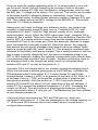
44. Since the S2 switch that was previously installed comes from the
factory as a “toggle” switch but our application uses a “pushbutton” input,
we’ll need to make a small modification to the mechanics of the switch to
suit our purpose.
Locate the switch “guide pin” on switch S2. With a small pliers, gently lift
the pin and rotate it so it does not remain in the toggle “groove”. See the
accompanying diagrams for help.
S w i tc h " G u i d e P i n "
T o g g l e P o s i ti o n
Switch "Guide Pin"
Pus h Button Pos ition
DN1 • 15
CONGRATULATIONS
You have just completed your DN1 NiCad battery conditioner unit. Take a
well deserved break now. Give your eyes a rest. When you return, be sure to
check over your work on the entire circuit board. Energizing the circuit board
with solder “bridges” or misplaced components can damage your kit. Don’t
throw away all your scrap component leads just yet, however, you’ll still need
a couple to set up your kit for its final operation.
DOCTOR NiCad BATTERY CONDITIONER SETUP
Its time to configure your Doctor NiCad for your individual application. We’ll
discuss a little theory first to more clearly understand the proper settings.
•
NiCad batteries have a capacity rating, or “C” value, associated with
them. This value is usually defined in an Ampere-Hour rating. Typically,
the larger the battery cell, the larger the Amp·Hr rating.
•
The quality of the NiCad is proportional to the charging rate of the
battery. That's why you have seen the exact same “looking” batteries (i.
e. same size, shape, and weight) while one is called a “fast charge” cell
and may cost twice as much! Many portable motor driven devices like
portable drills have higher capacity batteries for longer life. The higher
the quality of the cell the faster one can charge it, as high as a rate of 4
times the capacity (4C) of the cell. Be aware, however. that trying to
fast charge a cell not intended for this type of charge can cause the
cell to build up internal gasses too quickly and explode, regardless
of the complexity of the charger. If you cannot determine the proper
charging rate for your cell, the rate of C/2 is recommended.
•
Once the charging rate is determined, you can easily calculate the safety
“time” out required for worry-free operation. This time is roughly 1½
times the charge capacity of the cells. This “time out” feature ensures
that your batteries will not be charged for too long.
Here’s an example of how to determine the correct setup:
We have a battery pack consisting of 4 “AA” type cells. The pack is marked
as having 500mA hr cells with a quick charge rate of 1 Amp.
With a charging rate of 1 Amp, the cell is storing charge at a rate of twice the
capacity, or (2·C), The battery in an ideal situation will acquire a full charge in
one-half hours time, or mathematically speaking, 1 A · .5Hr = .5A-Hr or
500mA-Hr. Notice in the Safety Time Out Jumpering Chart (page 17) that for
a charge rate of 2C the time out will be 45 minutes.
DN1• 16
Fill in the chart with the ratings imprinted on your batteries. This should help
you to determine the proper jumper settings
Battery Type
Number of
Cells
Charge
Capacity (A•
Hr)
Charge
Current
(mA)
Time Out
Setting
(Min.)
DN1 FINAL ASSEMBLY INSTRUCTIONS
Use scrap resistor leads to form the proper “jumper” wires to configure your
conditioner. Use the parts diagram to identify the proper holes for the jumper
wires
Charging
Current
Jumpers
Used
250 mA
A-C, B-D
500 mA
C-D
1A
Setting the charge current too high can
cause the cell to explode! Consult the
battery manufacturers specifications for
proper charge current specifications.
A-F, C-D, B-E
CHARGING CURRENT SETUP
SAFETY TIME OUT CONFIGURATION SETUP
Charge
Rate
Jumper
TM1 to..
Jumper
TM2 to...
Charging
Time (Min)
C/2
H
No Connection
180
C
G
J
90
2C
No Connection
J
45
4C
H
J
23
DN1 • 17
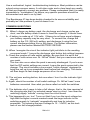
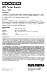
SETTING UP THE SWITCHES
You’ll need to configure the row of DIP switches for your battery pack now.
Since the minimum number of cells is at least one, the conditioner is already
set up for a single battery to begin with.
Switch No. 10 is reserved for the discharging current setup. When it is closed
the Doctor is in low current discharge mode, or about 140 mA drain from your
batteries. When Switch No. 10 is opened the discharging current is increased
to 280 mA, or the high current discharge.
Switches 1 - 9 should be set for the number of cells in the pack minus one
(remember, Dr. NiCad is set up for one cell to start, meaning that the first
resistor in the network is always in the circuit [R24]).
1
S w itc h
D o w n (O F F )
C o ntro l
S w itche s
1
0
S e t to N um b e r
o f C e lls to C ha rg e
m i n us o ne
S w itch
U p (O N )
H ig h / L o w
D isc ha rg e
R a te
H ig h = U p
Low = D own
(i.e . 4 C e ll P a c k , S w itc h e s 1 ,2 , a n d 3 U p , o r " O N
TESTING YOUR DOCTOR NiCad BATTERY CONDITIONER / CHARGER
Well, here it is, the moment of truth. Although you’re probably anxious to get
“charging”, now is the best time to double-check your work. It is far better to
discover a solder bridge, misplaced component, or incorrectly set switch now
before the circuit is energized than risk permanent component damage from
being too hasty! Review your configuration setups also.
DN1 CHARGE STATUS LED INDICATOR
When powered up, Dr. NiCad’s front panel LED is much more than a power
DN1• 18
Charger Status
Status LED “ON” time
Status LED “OFF” time
No Battery
No Light
No Light
Battery Connected
Awaiting Command
1/8 sec.
1/8 sec.
Discharging
1 3/8 sec
1/8 sec.
Continuous
N/A
Charge Complete
1/8 sec.
1/8 sec.`
Topping Off
1/8 sec.
1/8 sec.
Fast Charging
indicator. By changing the ON / OFF times this LED becomes a charging
status indicator! Use the following chart for an indication of what the doctor is
telling you.
POWER SUPPLY CONSIDERATIONS
The power supply used for the Dr. NiCad can very greatly depending on how
you set up your charger to work. While you may be able to “get away with”
many different types of supplies, what's recommended is a regulated 1214VDC supply capable of supplying at least 1.5 Amps of current
continuously. When using the doctor in the “field”, a 12 VDC car battery
works well as a power source. Be sure to remember that the center pin of the
input power connector, J3, should be connected to the positive ( + ) terminal
of the supply and the outer connector is attached to the negative, or ( - )
terminal.
THROTTLE UP !
With all our configuring steps behind us, it’s time to use the doctor!
1. Connect the battery (or batteries) to be charged to the +V (red) and -V
wires.
2. Connect the power input to the circuit.
3. Switch S3 to the “ON” position. The Status LED should come up in
either the “Fast Charging” mode or “Awaiting Command” mode.
4. To cycle the batteries, depress pushbutton switch S2. The Status LED
should display the discharging mode.
Once the batteries are discharging, Dr. NiCad will take it from there. The
conditioner will first discharge the cells to about .9 - 1.0 Volts per cell and
DN1 • 19
begin the Fast Charging mode.
The Benchmark IC will constantly monitor the pack and turn off the fast
charge when the cells are charged just to full capacity. Once this is
accomplished, it will periodically “top off” the cells with a high current burst,
and allow a slight trickle charge to flow.
Unfortunately, about the only thing to do for this initial check out is to watch
the lights blink - but it is also a good time to “measure” the capacity of your
cell. Start “timing” the charger just when it goes into fast charge mode.
Knowing the charge current rate (whatever you previously set it up at) and
the time for a full charge, (Amperes • Hours), you can get a fairly good
approximation of the health (capacity value) of your batteries.
What about those “mystery” batteries ?!
Often times the batteries are “hidden” in elaborate packs designed to fit in
video cameras, cordless phones, or RC racecars. The easiest way to
determine the number of cells in such a pack is to take the nameplate
voltage and divide by the number 1.2, the voltage of a single cell. For
example, a 7.2 V pack contains 7.2 ÷ 1.2 = 6 cells.
It can also be quite frustrating to connect the charger to these “oddball” type
packs. An inexpensive design idea is to fabricate your own holder with
assorted bits of wood and plastic. Surely a kitbuilder like you already has a
“junkbox” full of those priceless gems just waiting to be put to use to hold
your batteries. For example, an old discarded relay usually contains some
high current spring loaded contacts that make great connecting terminals for
such packs.
Be absolutely sure that you have the proper polarity identified on the battery
pack. Most are marked with a sticker or mark in the plastic case. If you can’t
figure out the charge capacity, go to your local home electronics store. Ask
about replacement cells; most likely the salesman will know what you need.
BATTERY WORKOUT
To keep your NiCad cells at their peak capacity, here are a few suggestions:
1) Alway deep cycle your batteries. Run them until they just begin to quit. It
is best to depress the “discharge” pushbutton after you initially hook up
the pack to Dr. NiCad.
2) Even when not in use, periodically “top off” the pack. This is also
DN1• 20
handled by the doctor, but if you have several packs, be sure to rotate
them (or maybe buy a few more Dr. NiCad Chargers).
BATTERY REPAIR ??!!
Many times we have older batteries or packs that don’t seem to hold a
charge at all, but they were so expensive that we couldn’t bear to toss them
in the trash. Well, your frugality (some people call it being cheap) has finally
paid off! Most of these extreme memory conditions can be “cycled” right out
of the pack. Simply configure your Dr. NiCad for the proper voltage, install
the pack, and press the discharge button. For best results, if you are
charging a cell greater than 1.5V (these are made up of many 1.5V cells),
charge the first few times on the C/2 (250 mA) setting. Additionally, you
should use the lower discharge setting also. This will give the cells a chance
to equalize their voltages, bringing more life back to the pack. Dr. NiCad will
run your batteries through a discharge/charge cycle. By continuing this
process over and over (the number of times depends on how bad the pack
was to start with) you can gradually build up your batteries capacity to full
strength again. This is probably the most satisfying use of your Dr. NiCad
charger (see, I told you I could fix ‘em)!
If when you initially hook up these “sick” battery packs the front panel
indicator wont let you discharge, don’t worry. The lower current trickle
charger is bringing the pack up to the correct minimum cell voltage to begin
rapid charging. Another method of “jump starting” a very old or abused pack
is to initially open one additional switch in the voltage divider ladder.This will
make the pack voltage appear higher to the charger, so the high current
charge will be initiated. Use caution when doing so, however, and after a few
minutes of charging be sure to reconfigure the switches for the proper
voltage setting. This method is only to be used as a last resort to save a
battery pack.
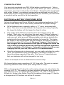
TROUBLESHOOTING INSTRUCTIONS
While we had hoped that it wouldn’t come to this, if you are having trouble
with your charger, here are a few suggestions.
By far the most common source of problems is due to misplaced parts or
poor solder connections. It’s always best to take a break before searching for
bad connections. A good way of checking component placement is to double
check the assembly steps going backwards from the last steps to the the
first. Bright lighting and a magnifying aid can be helpful in identifying
soldering problems. We’ve all made silly mistakes and never been able to
see them ourselves, so have a friend check your work, as well.
DN1 • 21
Use a methodical, logical troubleshooting technique. Most problems can be
solved using common sense. A volt-ohm meter and a clear head are usually
all that are needed to correct any problem. Please understand that it is nearly
impossible to “troubleshoot” by phone; any specific questions should be
documented and sent to us by mail.
The Benchmarq IC has been double checked to its ensure reliability and
probably isn’t the problem if your kit doesn’t run.
COMMON QUESTIONS
Q. When I charge my battery pack, the discharge and charge cycles are
short, and the battery doesn't seem to have the capacity it should have.
A. A battery is made up of 1.5V cells. If these do not have equal voltages,
your battery capacity may be very short. To correct this, charge the
battery on the C/2 (250 mA) setting, and discharge it using the low
current discharge setting four or five times. For further information,
please see the section labeled BATTERY REPAIR.
Q. When I energize the circuit the indicator light just blinks in the awaiting
command mode ? I press the discharge start button but nothing happens.
A. Check the number of cells switch settings. Be sure that it is set to the
number of cells minus one. Dr. NiCad “thinks” that you need more cells in
your pack.
This can also occur when the pack is severely discharged. If you’re sure
that the DIP switch settings are correct, Leave the pack connected to the
charger. The circuit includes a low current “trickle charger” designed to
bring the cell up to an acceptable level before fast charging. The doctor
will then begin its fast charge sequence all on its own.
Q. The unit was working before, but now when I turn it on the indicator light
stay off.
A. Again, check the number of cell switch settings. Dr. NiCad “sees” more
batteries connected than what you have called out with the switches.
Q. The batteries don’t seem to take a full charge, that is, the time required at
the charging rate that I’ve selected seems way too short. I can hear the
switching supply “whistle” coming from the circuit board.
A. This happened to us, too ! Turns out that if you turn the input voltage too
high that the higher currents created cause the large inductor in the
switching supply to “saturate” magnetically and lose its inductive
properties. Try reducing the input voltage to 12 - 14VDC, as this took
care of our fast charge problem.
DN1• 22
The Ramsey Kit Warranty
Please read carefully BEFORE calling or writing in about your kit. Most problems can be
solved without contacting the factory.
Notice that this is not a "fine print" warranty. We want you to understand your rights and ours too! All
Ramsey kits will work if assembled properly. The very fact that your kit includes this new manual is
your assurance that a team of knowledgeable people have field-tested several "copies" of this kit
straight from the Ramsey Inventory. If you need help, please read through your manual carefully, all
information required to properly build and test your kit is contained within the pages!
1. DEFECTIVE PARTS: It's always easy to blame a part for a problem in your kit, Before you conclude
that a part may be bad, thoroughly check your work. Today's semiconductors and passive components
have reached incredibly high reliability levels, and it’s sad to say that our human construction skills
have not! But on rare occasions a sour component can slip through. All our kit parts carry the Ramsey
Electronics Warranty that they are free from defects for a full ninety (90) days from the date of
purchase. Defective parts will be replaced promptly at our expense. If you suspect any part to be
defective, please mail it to our factory for testing and replacement. Please send only the defective part
(s), not the entire kit. The part(s) MUST be returned to us in suitable condition for testing. Please be
aware that testing can usually determine if the part was truly defective or damaged by assembly or
usage. Don't be afraid of telling us that you 'blew-it', we're all human and in most cases, replacement
parts are very reasonably priced.
2. MISSING PARTS: Before assuming a part value is incorrect, check the parts listing carefully to see
if it is a critical value such as a specific coil or IC, or whether a RANGE of values is suitable (such as
"100 to 500 uF"). Often times, common sense will solve a mysterious missing part problem. If you're
missing five 10K ohm resistors and received five extra 1K resistors, you can pretty much be assured
that the '1K ohm' resistors are actually the 'missing' 10 K parts ("Hum-m-m, I guess the 'red' band
really does look orange!") Ramsey Electronics project kits are packed with pride in the USA. If you
believe we packed an incorrect part or omitted a part clearly indicated in your assembly manual as
supplied with the basic kit by Ramsey, please write or call us with information on the part you need
and proof of kit purchase
3. FACTORY REPAIR OF ASSEMBLED KITS:
To qualify for Ramsey Electronics factory repair, kits MUST:
1. NOT be assembled with acid core solder or flux.
2. NOT be modified in any manner.
3. BE returned in fully-assembled form, not partially assembled.
4. BE accompanied by the proper repair fee. No repair will be undertaken until we have received the
MINIMUM repair fee (1/2 hour labor) of $25.00, or authorization to charge it to your credit card
account.
5. INCLUDE a description of the problem and legible return address. DO NOT send a separate letter;
include all correspondence with the unit. Please do not include your own hardware such as
non-Ramsey cabinets, knobs, cables, external battery packs and the like. Ramsey
Electronics, Inc., reserves the right to refuse repair on ANY item in which we find excessive
problems or damage due to construction methods. To assist customers in such situations,
Ramsey Electronics, Inc., reserves the right to solve their needs on a case-by-case basis.
The repair is $50.00 per hour, regardless of the cost of the kit. Please understand that our technicians
are not volunteers and that set-up, testing, diagnosis, repair and repacking and paperwork can take
nearly an hour of paid employee time on even a simple kit. Of course, if we find that a part was
defective in manufacture, there will be no charge to repair your kit (But please realize that our
technicians know the difference between a defective part and parts burned out or damaged through
improper use or assembly).
4. REFUNDS: You are given ten (10) days to examine our products. If you are not satisfied, you may
return your unassembled kit with all the parts and instructions and proof of purchase to the factory for
a full refund. The return package should be packed securely. Insurance is recommended. Please do
not cause needless delays, read all information carefully.
DN1 • 23
DN1 Dr. NiCad BATTERY CONDITIONER
Quick Reference Page Guide
Introduction to the DN1 ........................ 4
How it works......................................... 6
Parts list ............................................... 8
Schematic diagram .............................. 9
Parts Layout diagram ......................... 11
DN1 Assembly instructions ................ 12
Set-up configurations .......................... 16
Troubleshooting .................................. 21
Ramsey kit warranty ........................... 23
REQUIRED TOOLS
• Soldering Iron (WLC100)
• Thin Rosin Core Solder (RTS12)
• Needle Nose Pliers (MPP4 or RTS05)
• Small Diagonal Cutters (RTS04)
ADDITIONAL SUGGESTED ITEMS
Helping Hands Holder for PC Board/Parts
(HH3)
• Technician’s Tool Kit (TK405)
• Desoldering Braid (RTS08)
•
Price: $5.00
Ramsey Publication No. MDN1
Assembly and Instruction manual for:
RAMSEY MODEL NO. DN1 Dr. NiCad BATTERY
CHARGER / CONDITIONER KIT
RAMSEY ELECTRONICS, INC.
590 Fishers Station Drive
Victor, New York 14564
Phone
(585) 924-4560
Fax
(585) 924-4555
www.ramseykits.com
DN1• 24
TOTAL SOLDER POINTS
165
ESTIMATED ASSEMBLY
TIME
Beginner ...............5.0 hrs
Intermediate .........2.8 hrs
Advanced .............2.1 hrs