1
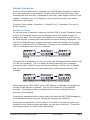
12 Volt Ultra-Portable Antenna Rotor System
Single Axis
Model 12PR1A
User Manual
Document Rev 1.1
Copyright 2013-14 © Portable Rotation
Patent Pending
Page 1
Warranty
All products sold by Portable Rotation are warranted against defects in material and workmanship for a period of 1
year from the date of shipment within North America, and for a period of one (1) year from the date of shipment to
outside of North America. If you believe this product you have purchased has a defect in material or workmanship
or has failed during normal use within the warranty period, please contact Portable Rotation at the below listed
contact information for assistance. If product repair or replacement is necessary, the Customer will be solely
responsible for all shipping charges, freight, insurance and proper packaging to prevent breakage in transit,
whether or not the product is covered by this warranty. All shipments of repaired or replaced products by Portable
Rotation will be F.O.B. from Roseville California, USA.
This warranty does not apply to defects resulting from any Customer actions, such as mishandling, improper
interfacing, operation outside of design limits, misapplication, improper repair, or unauthorized modification;
breaking the Warranty Seal voids all stated warranties. No other warranties are expressed or implied. Portable
Rotation liability shall be limited to the actual purchase price of any defective unit to which a claim is made, and
shall in no event include the Customer's manufacturing costs, lost profits or goodwill, or any other direct, indirect,
special, incidental or consequential damages whether based on contract, tort or other legal theory. Portable
Rotation is not responsible for any Damage to or caused by the installed Antenna in any use case.
In general: We do not warranty against Stupid ☺
Contact Information
For Sales inquiries:
http://[email protected]
For Support:
http://[email protected]
Shipping Address:
Portable Rotation
1214 Camino Capistrano
Roseville CA 95747
Website: http://www.portablerotation.com
Copyright 2013-14 © Portable Rotation
Patent Pending
Page 2
Contents
Warranty ................................................................ 2
Contact Information ................................................. 2
Contents ................................................................. 3
Introduction ............................................................ 4
Key Features ........................................................... 4
Specifications .......................................................... 4
Limitations .............................................................. 5
Included Items ........................................................ 5
efore First Use ......................................................... 6
Installation ............................................................. 6
Operation ............................................................... 7
New Deployment Configuration ...................... 7
Set the initial Heading .................................. 7
Set the Antenna Calibration ........................... 7
Setting your Call Sign / Vanity Text ................ 8
Normal Operations ....................................... 9
Manual Turn Mode ........................................ 9
Automatic Turn Mode...................................10
Aborting an Auto Turn Operation ...................10
Rotational Stoppage – Antenna Jam ..............11
Reset to Default Settings ........................................ 11
Remote Control ..................................................... 12
3rd Party Rotor Control Software ............................. 13
Operational Details ................................................ 14
Connection Information .......................................... 15
Copyright 2013-14 © Portable Rotation
Patent Pending
Page 3
Introduction
Thank you for purchasing the Portable Rotation 12 Volt Ultra-Portable Rotator
system, Model 12PR1A. This system has been designed for the Amateur Radio
Portable Enthusiast by Amateur Radio Operators who also enjoy operating portable.
This system is built with a simple to use user interface allowing easy operation
while still offering advanced features like ‘Auto Rotation’ and ‘Any-Direction
Calibration’. The heart of the system is a microprocessor that takes user input from
3 buttons and then controls the antenna motion, displaying antenna heading and
other information on a LCD screen. User entered information is saved in internal
memory along with antenna heading data; the controller can be turned off when
not being used to conserve power while no user or heading data is lost.
Key Features
•
•
•
•
•
•
•
•
•
•
•
•
Nominal rotation speed of 1RPM
Easy 3 button user interface with backlight 2x8 character LCD and 2 Notification LEDs
Full 360 degree rotation control – rotation stops at +/- 180 degrees from North. +/- 1 Degree
Resolution
PWM motor control with two user controlled turning speeds
Manual antenna rotation control
Automatic antenna rotation – set and forget
User programmable display message
‘Any-Direction Calibration’ offering easy antenna system deployment
Antenna Rotation Jam detection with auto stop
4 Conductor Rotor Cable (50 foot length provided)
USB Computer interface supporting the GS232A/B Rotator Control Protocol.
40mA idle current, less than 200mA normal turning current at 12 Volts
Specifications
•
•
•
•
•
•
•
•
9.0 Volt to 15 Volt DC Operation (12 Volt Nominal)
40maA idle current.
Will control up to a 2 Amp motor load; provided rotor head max current is 500ma.
Maximum Antenna load of 8 LBS1
Rotor Head weight: 2 lbs. 4 ounces.
Provided 50 Ft Cable weight: About 1 lbs. 2 ounces.
Controller Weight: 8 Ounces. (Total System weight: 3 lbs. 10 ounces).
4 conductor rotor cable – Minimum Gauge Size of 18 – Max Length supported – 100 Feet.
Note 1: Super Antennas YP-3 YAGI is the largest antenna tested with; though larger than specified by the Rotor Unit, no failures happened.
Copyright 2013-14 © Portable Rotation
Patent Pending
Page 4
Limitations
The 12PR1A Rotor unit is not designed for permanent installation. The system is
designed to be used for portable operations with antennas like what is sold by
companies like Buddy Pole, Super Antennas and Arrow Antennas. Exceeding the
specified maximum antenna weight may damage the Rotor Unit and will void all
expressed or implied warranties. It is not designed to withstand long term harsh
and extremely wet winter conditions.
The 6 Inch long Antenna Mast found at the top of the Rotor Unit is not to be
extended. A maximum length of 6 inches is recommended. Mounting a large sized
antenna above 6 inches may cause premature Rotor bearing failure.
Don’t:
Install Antennas Heavier than 8 pounds.
Operate with off center loading; make sure the antenna is balanced at the rotor mounting
point.
Extend the Antenna mounting shaft and mount antennas above 6 inches over the top of the
Rotor Enclosure.
Leave Rotor in extreme wet environments for extended times or high wind conditions.
Included Items
The following items are included as part of the Portable Rotator system:
•
•
•
•
•
•
•
•
•
12PR1A Ultra-Portable Antenna Rotor Controller.
12PR1A Ultra-Portable Antenna Rotor Mast Unit.
‘U’ Bolt hardware to attach Rotor Unit to antenna mast.
50 Ft - 4 Conductor Cable with screw type connectors.
4 – 6 inch Velcro cable ties.
6 Foot Pigtail Power cable (2.1mm x 5.5mm, Center Pin Positive).
3 Foot USB Cable.
Small Magnetic Compass.
This Users Document.
Copyright 2013-14 © Portable Rotation
Patent Pending
Page 5
Before First Use
Inspect the contents of the box and verify that the contents of the box match the
above list.
You will need to attach a 12 Volt power source to the ends of the provided pigtail
cable. Make sure to NOT cross the Positive lead with the Negative Lead. The
Positive lead on the provided power cable has the White Stripe.
Note: The controller electronics will work at a voltage as low as 6 Volts, but there is
not enough Voltage to operate the Rotors DC motor. 9 Volt operation is not
recommended when using large antennas as there is not enough energy for reliable
rotation.
Installation
Installing the Rotor system for portable use is a straight forward task and not much
different than installing your antenna without the Rotor System.
Before starting the installation VERIFY that the site is in a safe location to erect an
antenna system of the size you are planning. Make sure there are no overhead
power wires nearby. Also make sure there are no buildings, structures, or trees
that the turning antenna could strike and be damaged on. Even though this is a
low power 12 volt device, the high gear ratio of the mechanism could cause
damage if rotating your antenna into a fixed object.
Use the provided Velcro strips to attach the feed line Coax and Rotor Cable to the
mast in a few locations to keep the cables from moving in the wind. It is
recommended to attach the cables to the mast in a Northerly direction so that the
maximum rotation against the feed line will be 180 degrees. Remember to include
a service loop in the Coax to allow for the rotation.
Once the antenna/mast is up, connect the 4 conductor rotor cable to the Rotor
Controller and connect 12 Volts to the Controller using the provided power cable.
Take care to not cross connect the power connections.
Turn on the controller, and the following start up messages are displayed with the
final display showing the user configurable 8 character top line and the last known
antenna heading;
Portable
Rotation
Copyright 2013-14 © Portable Rotation
Model
12PR1A
PTBL RTN
Dir:155
Patent Pending
Page 6
Operation
New Deployment Configuration
After erecting your portable antenna system (including Tower/Mast, + guy lines,
Rotor Head, Antenna, Feed Line and Rotor Cable) you will need to calibrate the
antenna direction, and make any changes to the 8 characters of user
programmable message.
With the unique ‘Any-Direction’ Calibration feature of this controller, you can erect
the antenna system and not worry about the antenna heading at that time. This
saves time and the effort of trying to align the antenna to its proper heading while
you are busy trying to secure the antenna system.
Using the provided compass or other device, make note of the current heading of
the antenna. Again, you do not need to have the physical antenna heading set to
North or South when first erecting the antenna system; you will set the initial
heading of the antenna into the controller.
Set the initial Heading
Use the provided Compass or other reference to get the current Antenna heading.
Next go to the controller and while holding down the Mode button [Middle Button]
turn on the controller. Continue holding the button until the “Entr Dir” message is
displayed. Release the button.
Entr Dir
Dir:000
Enter New Initial Heading
Using the 3 Buttons –
When finished the new
Heading will be displayed
20M YP-3
Dir:270
The second line of the display will have “Dir:000 “ displayed. Notice the 100’s place
heading value has an underline cursor to identify the active location to change. Use
the CCW [Counts Up] and CW [Counts Down] buttons to count up or down to set
this value. You are allowed the value 0 through 3 in this location. When the first
value is set, press the Mode button, the cursor moves to the next location; the 10’s
place. Using the same procedure as before; select the value with the CCW and CW
buttons and then press the Mode button when the correct number is displayed. The
1’s place value is now selected; select the value and press the “Mode” button. The
current heading is now saved to memory and the new heading is displayed. If you
make an error, just redo the process by Power Cycling the controller.
Set the Antenna Calibration
The Rotor controller will try to stop the rotation on the exact degree position when
turning in the Automatic Mode or when in Remote Control Mode. It the Rotor
misses the stop location by more than 1 degree, you can try to adjust the system
response by setting the Antenna calibration to Optional (Opt).
To set the Controller to and from the Optional calibration mode, do the following;
while holding down the CW button [right Button] turn on the controller. Continue
holding the button until the “Ent ACal” message is displayed. Release the button.
Copyright 2013-14 © Portable Rotation
Patent Pending
Page 7
The value “Nml Opt” is displayed on the bottom line. Press the “CCW” button for a
Normal (Default) operation, or “CW” button for the Optional Antenna Calibration.
The “MODE” button has no effect in this operation. The Controller will display your
choice for a few seconds, then return to the normal operating mode.
Ent ACal
Turn On while Holding
the CW Button
Ent ACal
Nml Opt
Release the CW Button and then
press the CW Button to select
Ent ACal
Opt Ant
Selected Opt Antenna
is displayed for 2 seconds
Setting your Call Sign / Vanity Text
The 12PR1A Rotor Controller allows you to set and will display during idle time
where the controller is not turning the antenna, 8 Characters of your choice on the
top line. This can be your call sign, antenna information, or any other message you
want displayed. This information can be changed as often as you like.
The process of setting the text message is similar to setting the initial antenna
heading. While holding down the CCW button [left Button] turn On the Controller.
Continue holding the button until the “Ent Call” message is displayed, then Release
the button. The bottom line will now display the current message text and the first
character position will show that it is ready for input as it will be underlined. Use
the CCW and CW buttons to step forward or backwards through the Letters and
Numbers, pressing the MODE button after the correct character is selected. You
must do this operation for all 8 character positions. If no change is needed, just
press the MODE button to move to the next character.
After entering all 8 characters the display will refresh showing the new user
selected text on the top display row and the current antenna heading on the
bottom.
Copyright 2013-14 © Portable Rotation
Patent Pending
Page 8
Normal Operations
Once the initial configuration is complete, the 12PR1A Rotor Controller is ready to
turn your antenna to a new heading. As with most HF/6M/VHF/UHF beam type
antennas that this controller is designed to work with, exact degree accuracy is not
needed. A heading error of 15 degrees or even more will probably not make a
difference in your signal.
There are Three modes of operation; 1) Manual Turn, 2) Automatic Turn, and 3)
Remote Control.
Manual Turn Mode
To use this mode of operation, press and hold the CCW (Counter Clockwise) button
or the CW (Clockwise) button until the heading on the LCD display Shows the
heading you want. This will cause a full speed turn so remember to lead the turn
by a few degrees; releasing the button before the exact heading is displayed. You
can do a half speed turn by pressing the mode button and holding it at the same
time as you press the CW or CCW button. During any turn operation the GREEN
LED is on indication that a turn is in progress.
The controller is designed to not let you rotate past 180 degrees during either a CW
or CCW turn operation. This is to keep the antenna feed line from ‘wrapping’
around the mast. When the turn reaches the heading of 180 the turn is stopped
and you are informed that you have reached the virtual hard stop with an LCD
message.
When reaching the “MAX TURN” limit of 180 degrees, a message is displayed and
turning in that direction is blocked. The only turn allowed is in the opposite
direction. The degree symbol is replaced with an arrow to indicate the only
direction of turn allowed.
Pressing the opposite direction control button will clear the MAX TURN message as
the antenna turns away from the 180 degree maximum turn position.
During all turn operations, a short pause of 3 seconds is inserted from when you
release the turn direction button and when you can start a new turn. This allows
the antenna system to ‘settle’ at its new heading.
Copyright 2013-14 © Portable Rotation
Patent Pending
Page 9
As a turn is in process, the new heading value is saved to memory. When finished
with your turn, to save on battery power until the next time you want to turn the
antenna, you can turn off the Controller to conserve station power.
Automatic Turn Mode
This mode of turning to a new heading is useful when you need to make a large
antenna heading change; As an Example: Turn from 170 degrees to 190 degrees,
(340 degrees). You can either hold the “CCW” button down for the duration of the
turn or you can enter the Auto Turn Mode, input the new heading and let the
controller manage the turn for you. Remember a turn through 180 degrees is not
allowed by the controller.
To enter the Auto Turn Mode, with the control unit on, press and hold the MODE
button for 1 second. When you see the message “AutoTurn” in the display release
the button. You will enter the ‘Turn to Heading’ by the same method used when
setting the antenna heading calibration.
You will see on the second line of the display the message “Dir:000 “. Notice the
100’s place heading value has an underline cursor to identify the active location to
change. Use the CCW [Counts Up] and CW [Counts Down] keys to scroll up or
down to set this value. You are allowed 0 through 3 in this location. When the first
value is set, press the Mode button, the cursor moves to the next location; the 10’s
place. Using the same procedure as before; select the value with the CCW and CW
buttons and then press the Mode button when the correct number is displayed. The
1’s place value is now selected; select the value and press the Mode button. The
‘Auto-Rotation’ will start and the controller will automatically turn the antenna to
the new heading.
When the turn is completed, the new heading value is saved to memory and you
can turn off the controller to save on battery power until the next time you want to
turn the antenna.
The current antenna heading is displayed during the turn.
Aborting an Auto Turn Operation
At any time during the Auto Turn process, you can abort the turn by pressing the
MODE (Middle button). The turn will stop immediately saving the current heading
to memory.
Copyright 2013-14 © Portable Rotation
Patent Pending
Page 10
Rotational Stoppage – Antenna Jam
In the event that during the rotation of the Antenna, it comes into contact with a
structure, tree, or other unmovable object that stalls the turn for more than 1
second, the Controller will detect that the turn has stopped and will turn off the
motor, display a message on the LCD and turn on the RED led with a constant ON
condition.
If a Rotational Jam does occur, stop any further attempts at antenna rotation and
go inspect the antenna site. The drive motor is relatively small but has a very high
gear reduction, and when operating from a 12 source can produce enough torque to
possibly damage a light duty antenna.
To clear the condition after you have resolved the physical condition causing the
Antenna Jam, you can rotate the antenna in the opposite direction that caused the
JAM or power-cycle the Controller.
Reset to Default Settings
The controller can be reset to the default out of box settings, clearing any user
entered settings and resetting all internal stored states. To reset the Controller,
turning on the unit while holding down all 3 buttons until the sign on messages are
displayed. The Firmware Version will be displayed and you will be asked if you
want to reset the Controller. Press the CCW button for Yes or the CW button for
No. If yes the controller then returns to normal operation, with factory defaults.
If the controller is experiencing erratic operations in heading reporting or other
operations, perform the above Reset operation.
Copyright 2013-14 © Portable Rotation
Patent Pending
Page 11
Remote Control
The Rotor Controller can be attached to a computer system using the USB Type-B
jack on the front of the Controller. The controller supports the GS232A/B Rotator
Control Protocol. Serial Parameters supported are: 9600 baud, 1 Start, 1 stop, No
Parity, No Handshake
In this protocol the following Commands are supported:
Start Left Turn:
Start Right Turn:
Stop All Turn:
Auto Turn to new Heading:
Report Current Heading:
L Command
R Command
A or S Command
M=XXX Command
C Command and replies with ‘AZ=XXX<CR>’
To enter the Remote Control mode of operation, with the controller on, press and
hold both the CW and CCW buttons. The display will show the following message:
The ‘Antenna Jam’ Red LED will flash each time the controller receives a command
from the host computer.
While in the Remote Control Mode, manual control of the rotor is disabled.
To exit the Remote Control mode, Press both CW and CCW buttons a second time.
To use the onboard USB interface your computer needs to have the FTDI Virtual
COM Port driver loaded. This driver is available on the FTDI Web Site at the
following URL: http://www.ftdichip.com/Drivers/VCP.htm
From this location select the driver based on you Operating System and install as
instructed by FTDI.
Copyright 2013-14 © Portable Rotation
Patent Pending
Page 12
3rd Party Rotor Control Software
There are a number of applications on the market that can be used to Remotely
Control the 12PR1A Ultra-Portable Rotor system. One such program is called
‘PstRotatorAz’ and is sold by YO3DMU. It is a full featured Windows compatible
application that will run stand alone or as an interface between other applications.
Website: http://www.qsl.net/yo3dmu/index_Page346.htm
After installing the software and entering your registration code you must configure
the software by setting the COM Port and Controller Type.
Under the ‘Communications’ Tab – Select ‘AZ COM Port’ and select the USB Port
that the Controller is attached to.
Under the ‘Setup’ Tab:
- Select ‘Controller’ and select ‘GS-232 Yaesu 360 deg’
- Select ‘Refresh Rate’ and set to 1 Sec
- Select ‘Start in Manual Mode’
- Select “Antenna Limits’ and set as follows:
There are many other settings that can be set based on user needs. The ones
listed are minimum needed to enable this software for this controller.
We have tested this application on Windows XP, Windows 7 32-Bit and Windows 7
64-Bit and the USB driver listed on page 15 with no problems found.
The USB Port is powered by the Host PC so you can turn off the Controller and the
USB port will not be dropped by the attached controller
Copyright 2013-14 © Portable Rotation
Patent Pending
Page 13
Operational Details
The diagram below can be used as a reference to the basic turning operation of the
Rotor System.
Port Rtn
Dir : 000
When the antenna Heading is between
359 degrees North and 180 Degrees
Aouth, turning the antenna to the East
requires a Clockwise (CW) turn. You
cannot turn Counterclockwise (CCW)
and pass through 180 degrees South.
When the antenna Heading is between
000 degrees North and 180 degrees
South, turning the antenna to the West
requires a Counterclockwise (CCW) turn.
You cannot turn Clockwise (CW) and
pass through 180 degrees South.
359|000|001
NORTH
WEST
270
Antenna
Direction
EAST
090
SOUTH
When at a South-South-West
heading and turning to a SouthSouth-East heading use the ‘Auto
Turn’ feature to turn the antenna.
When at a South-South-East
heading and turning to a SouthSouth-West heading use the ‘Auto
Turn’ feature to turn the antenna.
180 / 180
MAX TURN
Dir:180
Copyright 2013-14 © Portable Rotation
MAX TURN
Dir:180
Patent Pending
Page 14
Connection Information
The rotor cable is a 4 conductor, 18 Gauge, 7 strand cable using female connectors
at each end.
Pin
Pin
Pin
Pin
1
2
3
4
to
to
to
to
Pin
Pin
Pin
Pin
1
2
3
4
–
–
–
–
Motor (+/-)
Motor (-/+)
Sensor (+)
Sensor (-)
Below are the connection details for the Rotor Controller to Rotor Head Connection.
Required Cable Connector: 4-Pin MIC connector: Philco P61605
An extension cable will require 1 4-Pin male and 1 4-Pin female connection. Cable
length over 100 feet are not supported. An optional 50 Ft extension cable can be
purchased from Portable Rotation.
Caution should be used if making your own cable as connecting the Motor Drive
pins to the rotational sensor may damage the controller and require replacement of
the Controller and/or the Rotor Unit.
Copyright 2013-14 © Portable Rotation
Patent Pending
Page 15