1
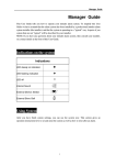
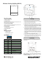
Wireless Outdoor Bell Box (BX-S1) Parts Description 1. Mounting Holes x 4 2. Tamper Switch The tamper switch protects the device from being opened or from being removed from mounting surface. Learning 1. Open the front cover and locate the Function Switch Block. 2. Use a sharp object to set Dip SW3 & SW4 on the function switch block to your desired alarm length. 3. Enter learning mode for your control panel. 3. Function Switch Block 4. Slide the Power Switch to ON position to power on the Bellbox. Contains 7 DIP Switches to enable the learning mode and to set the alarm period of siren and strobe light. 5. Slide Dip SW1 to the ON position. The Bell Box LED 1 & 3 will flash once with a short beep. The BX-S1 is now in learning mode. After 3 seconds, the Bell Box will send out a learning code, the LED 1 & 3 will flash once to confirm 4. Power Switch To enable/disable the power supply 5. Securing Screw 6. LEDs Package Content 1 x Outdoor Bell Box 4 x large wall plugs and screws 4 x 1.5V D alkaline batteries Dip Switch 6. If the Control Panel receives the learning signal, please refer to the Control Panel manual to complete the learning process. When learning is complete, the Control Panel will send signal to the Bell Box to confirm. The Bell Box will sound a short beep and LED 1 & 3 will flash once to indicate learning is successful. 7. If the Control Panel fails receive a learning code, slide Dip SW1 back to OFF, and then ON position again to enter learning mode again. 8. If the Bell Box does not respond, please remove the Bell Box from the control panel and repeat steps 3-6 again. 9. Slide Dip SW1 to the OFF position to leave learning mode. If you do not slide Dip SW1 back to OFF position, the Bell Box will automatically leave the learning mode in one hour. Installation SW1 Siren Learning OFF Normal operation ON Learn-in mode SW2 Strobe Activation OFF only during siren alarm period ON until alarm is disarmed SW3 SW4 Siren Duration OFF OFF 3 min. ON OFF 5 min. OFF 10 min. ON ON 1 second (test) ON SW5 Reserved SW6 Memory Reset OFF Normal ON Clear Memory SW7 Supervision OFF Supervision function disable ON Supervision function enable For further detail please see Learning and Operaion. The Outdoor Bell Box has 4 mounting holes on the back cover for wall mounting. Mounting Holes x4 Before Installation, refer to your Control Panel manual to temporarily disable the Siren Tamper function to avoid accidental alarm trigger. 1. Use the 4 mounting holes on the back to mark position on the wall. * Siren Audio indication will be effected by the Confirmation ON / OFF setting in your Control Panel settings. 2. Drill holes into the wall using the mounting holes as template. Battery 3. Fix the base onto the wall with the screw and plugs provided. The Bell Box uses four 1.5V D alkaline batteries as its power source. It also features low battery detection function to notify the Control Panel when battery voltage is low. 4. Replace the front cover onto the base. 5. Enable the Siren Tamper function on you Control Panel. When mounting the Bell Box, please take note of the following points: Mount on the external wall at a prominent location. Mount as high as possible out of easy reach. When the Bell box is on low battery, follow the procedure below to change the batteries. 1. Temporarily disable the Bell Box’s tamper protection function (please refer to your Control Panel manual for detail). The Bell Box will sound a beep to indicate the tamper is disabled. 2. Remove the front cover. 3. Remove the four screws fixing the battery compartment and take off the compartment lid. Operation 4. Remove the old batteries and press the Tamper Switch twice to discharge. Tamper Switch The Bell Box is protected by a tamper switch which will be activated if the Bell Box is removed from the mounted location, or its cover opened. When installing the Bell Box, please make sure the tamper switch is properly compressed against the wall, and the front cover is secured with screw. 5. Insert the new D cell alkaline batteries into the battery compartment according to correct polarity. Before installing the Bell Box, changing mounting location or batteries, please make sure to disable the tamper switch temporarily using your Control Panel’s Siren Tamper function and enable the tamper switch again after finish working on the Bell Box. Please refer to your Control Panel manual for detail. 7. Replace the battery compartment lid and front cover 6. The Bell Box will emit beeps and flash when the last battery is inserted. 8. Enable the tamper protection function through your Control Panel. The Bell Box will sound a beep to indicate. Specification Siren Audible Performance The siren produces a minimum of 104 dBA sound pressure at 1 meter range when activated. For Burglar and Panic Alarm, the Bell Box gives a continuous alarm sound. For Fire / Water alarm, the Bell Box gives an intermittent alarm sound of 2-sec siren followed by a 1 sec interval. The siren is silenced when either the programmed siren length expires or when the Control Panel is disarmed to turn off the siren. Please refer to Dip Switch table above to set your desired alarm length through Dip Switch SW3 and SW4 setting. Environmental Condition -10°C to 40°C, relative humidity 85% non-condensing. Radio 433 MHz Strobe (LED) Light FCC Statement When the Bell Box is activated, the LED strobe light will also flash to indicate the Bell Box is alarming. The duration of strobe light flash is determined by Dip Switch SW2 setting. When set to OFF, the strobe light will flash according to the alarm length set by Dip Switch SW3 and SW4. When set to ON, the strobe light will flash after the alarm length has expired until the control panel is disarmed. This device complies with Part 15 of the FCC Rules. Operation is subject to the following two conditions: (1) This device may not cause harmful interference, and (2) This device must accept any interference received, including interference that may cause undesired operation. Audio & Visual Status Indication Table The Bell Box will activate its siren and strobe light to notify the user of system status, please refer to below table. Siren Audio Strobe light indication FCC Caution: To assure continued compliance, any changes or modifications not expressly approved by the party responsible for compliance 1 beep* 3 LED flashes at once may void the user's authority to operate this equipment. (Example Disarm 2 beeps* Sequentially flashes for 1 cycle or peripheral devices). Arm (Low Battery) 5 beeps 3 LED flashes for three times Disarm (Low Battery) 5 beeps Sequentially flashes for 2 cycles Arm (Tamper) 5 beeps 3 LED flashes for three times Disarm (Tamper) 2 beeps* Sequentially flashes for 2 cycles Previous alarm warning 3 sec beep Sequentially flashes for 2 cycles Tamper Alarm Continuous beeps Sequentially flashes Entry/Exit Sound Count-down beeps None Arm/Home - use only shielded interface cables when connecting to computer