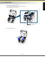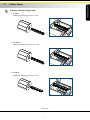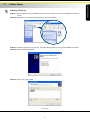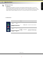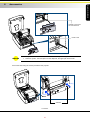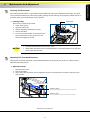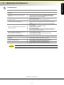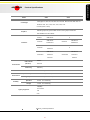
1
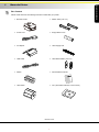
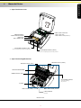
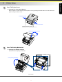
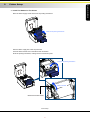
USER MANUAL G500 SERIES User Manual : G500 series Version : Rev 1.3 Issue Date : 2012.11.07 P/N : 920-014011-00 產品規格 G500 機種 G530 列印模式 熱感式/熱轉式兩用 解析度 203 dpi (8 dot/mm) 300 dpi (12 dot/mm) 列印速度 5 IPS (127 mm/s) 4 IPS (102 mm/s) 列印寬度 4.25” (108 mm) 4.16” (105.7 mm) Min. 0.16” (4 mm)** Min. 0.39” (10 mm) Max. 68” (1727 mm) Max. 30” (762 mm) 列印長度 32 Bit RISC CPU 處理器 8MB Flash (使用者可用容量為4MB) 記憶體 16MB SDRAM 感應器形式 反射式感應器: 可移動式; 透光式感應器: 中置型固定式 連續紙、間距標籤紙、黑線標記紙或打孔紙等,標籤長度可自動偵測或手動命令強制 紙張類型 控制。 紙張寬度 1” (25.4 mm) Min. - 4.64” (118 mm) Max. 紙張厚度 0.003” (0.06 mm) Min. - 0.01” (0.25 mm) Max 紙捲外徑 Max. 5” (127 mm) 紙捲軸芯 1”, 1.5”, 3” (25.4 mm, 38.1 mm, 76.2 mm) 紙張規格 碳帶規格 材質 一般蠟質型、混合型、抗刮樹脂型 長度 981’ (300 m) 寬度 1.18” Min - 4.33” (30 mm - 110 mm) Max 最大外徑 2.67“ (68 mm) 軸芯 1” (25.4 mm) EZPL, GEPL, GZPL auto switch 程式語言 標籤排版軟體 隨機搭贈軟體 Driver DLL GoLabel (for EZPL only) 支援Windows 2000, XP, Vista, 7, Windows Server 2003 & 2008 支援Windows 2000, XP and Vista 附錄_產品規格 039 G500 Series 附錄 Please read the following instructions carefully. Keep the equipment away from humidity. Before you connect the equipment to the power outlet, please check the voltage of the power source. Make sure the printer is off before plugging the power connector into the power jack. It is recommended that you connect the printer to a surge protector to prevent possible transient overvoltage damage. Be careful not to get liquid on the equipment to avoid electrical shock. For safety and warranty reasons, ONLY qualified service personnel should open the equipment. Do not repair or adjust energized equipment under any circumstances. Safety Instructions P/N : 920-014011-00 G500 Series SAFETY INSTRUCTIONS 1-1 Barcode Printer Box Content Please check that all of the following items are included with your printer. Barcode Printer Ribbon Hubs ( set of 2 ) Power Cord Empty Ribbon Core AC Adapter Label Supply Hub USB Cable Label Guide Plates ( set of 2 ) Ribbon Quick Reference Guide Label Stock CD ( with QLabel software / user manual ) Barcode Printer 001 1 G500 Series 1 Barcode Printer 1-2 G500 Series 1 Getting To Know Your Printer Device Overview Front View TOP COVER OPERATION PANEL FRONT COVER COVER OPEN BUTTONS Release buttons for opening the printer cover Rear View FAN-FOLD LABEL INSERT Feed slot for external label feeding ETHERNET PORT* SERIAL PORT ( RS-232 )* POWER SWITCH - ON - OFF USB PORT POWER JACK NOTICE The combination of connection ports may vary with printer model. Barcode Printer 002 2 G500 Series 1 Barcode Printer Open The Printer Cover LABEL SUPPLY MODULE RIBBON MODULE - LABEL SUPPLY HUB - RIBBON FEED MECHANISM - LABEL GUIDE PLATES ( SET of 2 ) - RIBBON HUB - EMPTY RIBBON CORE ADJUSTMENT SCREW ( LEFT ) Screw for adjusting the print head pressure ADJUSTMENT SCREW ( RIGHT ) Screw for adjusting the print head pressure Open The Printing Mechanism RELEASE CATCH ( RIGHT ) RELEASE CATCH ( LEFT ) PRINTING MECHANISM RIBBON SUPPLY HUB ADJUSTMENT SCREW Screw for adjusting the print line PLATEN LABEL GUIDE ( RIGHT ) LABEL GUIDE ( LEFT ) LABEL SENSOR Movable Barcode Printer 003 3 2-1 Printer Setup Open The Printer Cover Pressing The Cover Open Buttons Place the printer on a flat surface. Open the printer cover by pressing the release buttons on both sides of the printer housing and lift the cover. Pressing the button Pressing the button COVER OPEN BUTTONS Release buttons for opening the printer cover. Lift the printer cover backward 2-2 Open The Printing Mechanism Pressing The Release Catches Release and lift the printing mechanism. RELEASE CATCHES Lift the printing mechanism Pressing Pressing Printer Setup 004 4 G500 Series 2 2-3 Printer Setup G500 Series 2 Loading The Ribbon A New Ribbon Module Installation Place the new ribbon on the hub which forms a ribbon supply hub. Place on the hub RIBBON SUPPLY HUB RIBBON HUB NEW RIBBON Place the empty ribbon core on the hub which forms a ribbon rewind hub. Place on the hub RIBBON FEED MODULE RIBBON HUB EMPTY RIBBON CORE Stick the ribbon supply hub on the ribbon rewind hub and wind the rewind hub 2~3 circles. Wind the ribbon around the core Printer Setup 005 5 Printer Setup G500 Series 2 Install The Ribbon On The Printer Place the ribbon supply hub at the back of the printing mechanism. Insert into the printing mechanism Pass the ribbon supply hub under the print head. Insert the ribbon rewind hub on the ribbon feed mechanism. Close the printing mechanism, making sure that it clicks into place. Place on the printing mechanism Wind to the back RIBBON FEED MECHANISM Printer Setup 006 6 2-4 Printer Setup Loading The Label Roll A New Label Roll Module Installation Place the label stock on the label supply hub, attach the guide plates to the label stock holder. LABEL STOCK Place on the ribbon hub LABEL SUPPLY HUB LABEL GUIDE PLATES Install The Label Roll Module On The Printer Now load the label stock into the printer. Place on the printer Printer Setup 007 7 G500 Series 2 Printer Setup G500 Series 2 Release the printing mechanism and lift it. Pass the labels through the label guides up to the tear-off plate. Adjust the label guides to the label width. Through the label guides LABEL GUIDES Close the printing mechanism. Close Printer Setup 008 8 2-5 Printer Setup G500 Series 2 Installing The Label Supply Hub 1" Cores Installing the label supply hub for 1" cores. 1.5" Cores Installing the label supply hub for 1.5" cores. 3" Cores Installing the label supply hub for 3" cores. Printer Setup 009 9 2-6 Printer Setup Preparing For Tag Printing In tag printing, the tag hole indicates the height of a label. During adjustment, the sensor must therefore be positioned directly below the tag hole as shown in the illustration. The tag hole should be at least 3 mm in diameter to ensure correct functioning. SENSOR POSITION Printer Setup 010 10 G500 Series 2 2-7 Printer Setup Connecting The Printer To The Host Computer Please make sure that the printer is switched off. Connect the power cord to the AC adapter and connect the adapter to the printer. Connect the USB / parallel cable to the printer and host computer. Switch on the printer. The LED indicator should now lights up. B1 A1 POWER SLOT USB PORT A1 B1 POWER JACK USB PORT B2 USB PORT A2 PLUG A2 THE SOCKET OF THE WALL B2 USB PORT Printer Setup 011 11 G500 Series 2 2-8 Printer Setup Installing The Driver STEP-01Insert the product CD in the CD/DVD drive of the host computer and open the "Seagull-Driver" folder on the CD. STEP-02Select the icon for the driver file and click it to start the installation. STEP-03Follow the instructions on the screen. The Driver Wizard guides you through the installation procedure. STEP-04Select "Install printer drivers". STEP-05Specify your printer model. Printer Setup 012 12 G500 Series 2 Printer Setup STEP-06Specify the port used to connect the printer to the host computer. STEP-07Enter a printer name and assign the appropriate rights. STEP-08Once the installation is complete, a summary of the printer settings is displayed. STEP-09Check whether the printer settings are correct and click "Finish" to start copying the driver files. STEP-10Wait until copying is complete, then finish the installation. Printer Setup 013 13 G500 Series 2 Printer Setup STEP-11Once the driver installation is complete, the new printer should appear in the "Printers and Faxes" folder. Printer Setup 014 14 G500 Series 2 3-1 Operation Panel LED Operation Panel FEED Button When you press the FEED button, the printer moves the label to the defined stop position. If you are using continuous labels, pressing the FEED button will move label stock until you release the button again. If you are using individual labels, pressing the FEED button will move only one label. If the label does not stop at the correct position, please run the auto calibration (See Section 3-2. for the label size calibration function) on the label stock. LED Indicators LED indicator READY Status Description X Standby mode The printer is ready for operation. 2 x 2 beeps 2 x 3 beeps 2 x 4 beeps Error mode The printer has detected an error. (See Section 3-3. for Error alerts) Green STATUS X READY X STATUS Beeps Red Operation Panel 015 15 G500 Series 3 3-2 Operator Panel Label size calibration and Self Test Page The printer can automatically detect and store label height. That means the host computer does not need to transmit the label height to the printer. And the self-test function lets you check whether the printer is functioning normally. Here is how you run the label size calibration and self test. STEP-01Check that the label stock is loaded correctly. STEP-02Switch off the printer. STEP-03Switch the printer on again, keeping the FEED button pressed. When the READY LED starts to flash red and the STATUS LED lights up orange, release the FEED button. The printer will now measure the label stock and store the label height. STEP-04Once the printer has successfully measured the label stock, it will print a self-test label. The contents of a self-test printout are listed below. G500 GX.XXX USB S/N: XXXXXXXX Serial port : 96,N,8,1 MAC Addr: xx-xx-xx-xx-xx-xx DHCP Enable IP xxx.xxx.xxx.xxx Gateway xxx.xxx.xxx.xxx Sub-Mask xxx.xxx.xxx.xxx ############################### 1 DRAM installed Image buffer size : 1500 KB 000 FORM(S) IN MEMORY 000 GRAPHIC(S) IN MEMORY 000 FONT(S) IN MEMORY 000 ASIAN FONT(S) IN MEMORY 000 DATABASE(S) IN MEMORY 000 TTF(S) IN MEMORY 2048 KB FREE MEMORY ^S4 ^H10 ^R000 ~R200 ^W108 ^Q100,0,0 ^E12 Option : ^D0 ^O0 ^AD Reflective AD : 1.80 2.01 1.89 [0.21_0] Code Page : 850 Default state= No Model & Version USB ID setting Serial port setting MAC address of Ethernet port IP protocol setting IP address of Ethernet port Gateway setting Netmask setting Number of DRAM installed Image buffer size Number of forms Number of graphics Number of fonts Number of Asian fonts Number of Databases Number of Scalable fonts Free memory size Speed, Density, Ref. Point, Print direction Label width, Form length, Stop position Cutter, Label Dispenser, Mode Sensor Setting Code Page Printer is on factory default Operation Panel 016 16 G500 Series 3 3-3 Operator Panel Error Alerts In the event of a problem that prevents normal functioning of the printer, you will see an error message on LED indicators and hear some beep signals. Please refer to below table for the error alerts. Light on Flashing LED indicator READY STATUS Beeps 2 x 4 beeps None Description Solution The printing mechanism is not correctly closed. Open the print mechanism and close it again. High temperature at the print head. Once the print head has cooled down, the printer switches to standby mode. No ribbon is installed and the printer displays an error. Make sure that the printer is set to direct thermal printing mode. The ribbon is finished or the label supply hub is not moving. Replace the ribbon roll. No paper is detected. Make sure that the label sensor is positioned correctly. If the sensor still does not detect the paper, run the auto-detection function again. Paper is finished. Replace the label roll. Printer feed problem. Possible reasons: the print medium has become trapped around the rubber roll; the sensor cannot detect a gap or black mark between the labels; there is no paper. Please reset the sensor. The memory is full. The printer prints the message "File System full". Delete unnecessary data or install additional memory. Unable to find file. The printer prints the message "File Name Not found". Use the "~X4" command to print all files. Then check whether the files exist and whether the names are correct. A file of the same name already exists. The printer prints the message "Duplicate Name". Change the name of the file and try storing it again. 2 x 3 beeps 2 x 2 beeps 2 x 2 beeps Operation Panel 017 17 G500 Series 3 4-1 NetSetting for Ethernet Installing The NetSetting software The NetSetting software is used to manage the network configurations when connecting the printer via Ethernet port. It is available on product CD or can be downloaded from official website. To install the NetSetting, please follow below steps. STEP-01Insert the product CD in the CD/DVD drive of the host computer and open the "Ethernet" folder on the CD. STEP-02Select the icon for the NetSetting installation file and click it to start the installation. STEP-03Follow the instructions on the screen. The Setup Wizard guides you through the installation procedure. STEP-04Specify the “Installation Folder". STEP-05Click ”Next” to start the installation. STEP-06Once the installation is completed; you will see the NetSetting icon on your desktop. NetSetting for Ethernet 018 18 G500 Series 4 4-2 NetSetting for Ethernet The interface of NetSetting Click the NetSetting icon to start the program; you will see the start page as below. The start page will display the basic information of connected printer and your PC. Click the magnifier icon to search the Godex printers which are connected via Ethernet port in you network environment. Once a connected Godex printer is detected, it will be listed on the start page. There are six tabs on the top of interface which can configure different types of network settings. But for the data security reason, you need correct password to enter the configuration pages. NOTICE The default password is “1111”, you can change the password later from the “IP Setting” tab. NetSetting for Ethernet 019 19 G500 Series 4 NetSetting for Ethernet IP Setting The IP Setting tab can change the printer name, Port number, Gateway setting and the password for configuring the printer. You can also set the printer’s IP address ether by DHCP or by Static IP. You can press “Set” button to apply the settings and “ReGet” button to refresh the setting values. NOTICE To fully benefit from the NetSetting software, you should be familiar with basic networking principles. Please contact your network administrator for related network setting information. NetSetting for Ethernet 020 20 G500 Series 4 NetSetting for Ethernet Alert Path Setting NetSetting will send the alert messages to designated mail account when the error happened on printer. The alert messages are sent by SMTP (Simple Mail Transfer Protocol) or SNMP (Simple Network Management Protocol). You can set or change the configurations of SMTP and SNMP on this “Alert Path Setting” tab. You can press “Set” button to apply the settings and “ReGet” button to refresh the setting values. NetSetting for Ethernet 021 21 G500 Series 4 NetSetting for Ethernet Alert Message Setting For the alert message notification function, you can decide which error cases need to be sent out to the operator. Moreover, the alert messages can be set to be sent by SMTP, SNMP or both. You can press “Set” button to apply the settings and “ReGet” button to refresh the setting values. NetSetting for Ethernet 022 22 G500 Series 4 NetSetting for Ethernet Printer Configuration Set or change the configurations of connected printer. Most of key settings for the printer operation can be done by this setting page. You can press “Set” button to apply the settings and “ReGet” button to refresh the setting values. NetSetting for Ethernet 023 23 G500 Series 4 NetSetting for Ethernet User Command The “User Command” tab provides a communication interface for operator to control the printer. Input printer commands in "Input Command" window and press “Send Command” button, the commands will be sent to the printer. For some commands that will return response message, the message will be displayed in "Output Message" window. You can press “Send Command” button to send printer commands via Ethernet port and control the printer remotely. NetSetting for Ethernet 024 24 G500 Series 4 NetSetting for Ethernet Firmware Download On “Firmware Download” tab, the current version of printer firmware will be showed on the screen. If you need to update the printer firmware, just specify the file location of firmware file and press “Start Download Firmware” button. The printer firmware then can be updated remotely. In addition to the firmware update, you can press “Recover To Factory Settings” button to restore the printer configurations back to factory default. NetSetting for Ethernet 025 25 G500 Series 4 Accessories G500 Series 5 Preparation Steps Before installing the optional modules, please make some preparations as follows. STEP-01 Turn Off The Printer : Remember to switch off the printer before installing any module. STEP-02 Open The Printer Cover : Open the printer cover by pressing the release buttons on both sides of the printer housing. Please see the Section 2-1 for further information about Open The Printer Cover. STEP-03 Open The Printing Mechanism : Press the release catches on both sides of the printing mechanism to open and lift the printing mechanism. Please see the Section 2-2 for further information about Open The Printing Mechanism. STEP-04 Remove The Front Cover : To remove the front cover, press in the two plastic release tabs. Remove the front cover as shown in the illustration. FRONT COVER Pressing the two plastic release tabs PLASTIC RELEASE TABS Release the front cover Accessories 026 26 5-1 Accessories Installing The Label Dispenser The Overview Of The Label Dispenser CONNECT CABLE OF LABEL DISPENSER PAPER SENSOR PAPER FEED ROLLER LABEL DISPENSER MODULE SCREWS NOTICE A label liner thickness of 0.006 mm ± 10% and a weight of 65 g/m2 ± 6% are recommended. The label dispenser will take labels up to a max. width of 110 mm. When using the label dispenser, set the stop position to 9 mm. Preparation Steps Please complete the preparation steps before installing the label dispenser. Accessories 027 27 G500 Series 5 Accessories G500 Series 5 Installing The Label Dispenser Connect the dispenser cable to the lower jack as shown in the illustration on the right. LOWER JACK CONNECT CABLE OF LABEL DISPENSER MODULE NOTICE The printer must be switched off, or the motherboard may be damaged! There are 2 jacks : the lower jack is for the dispenser, the upper jack for the cutter. Install the dispenser by pressing down first its right-hand side and then its left-hand side. RIGHT-HAND SIDE LEFT-HAND SIDE LABEL DISPENSER MODULE Accessories 028 28 Accessories G500 Series 5 Secure the dispenser using the screws provided for this purpose. Locking Locking SCREWS Install The Label Roll Module On The Printer Pass the paper through the guides. Through the label guides LABEL GUIDES NOTICE Labels should be at least 25 mm high. Accessories 029 29 Accessories G500 Series 5 Remove the first labels from the liner, so you can pull the liner through the guides. THE PAPER FEED ROLLER OF PRINTER Tear a label THE FIRST LABEL Pass the label stock through the printer as shown in the illustration on the right. LABEL LINER LABEL STOCK THE PAPER FEED ROLLER OF LABEL DISPENSER MODULE THE PAPER FEED ROLLER OF PRINTER Accessories 030 30 Accessories G500 Series 5 Close the label dispenser and the print mechanism. The installation is completed now. Close Press the FEED button to feed the label. The label will be peeled from the liner while it passes through the label dispenser. NOTICE There is a paper sensor on the Label Dispenser module. It will stop the printing if it is covered by label. Remove the last printed label and the printer will then continue to print next label. PAPER SENSOR Remove the label Press the FEED key LABEL Accessories 031 31 LINER 5-2 Accessories Installing The Cutter The Overview Of The Cutter CONNECT CABLE OF CUTTER MODULE CUTTER MODULE SCREWS Remember to switch off the printer before installing the cutter. Do not use to cut adhesive labels! Glue residue will be left on the cutter blade and impair its NOTICE functioning. The cutter has a blade life of 400,000 cuts when using paper liner which is 250μm thick and 3 inches wide. SUGGESTION You can cut paper with a max. width of 116 mm. With the cutter installed, set the stop position in QLabel to 28, or the E value to 28. Before installing the cutter module, remove the cutter cover as shown in the illustration. Remove the cutter cover Preparation Steps Please complete the preparation steps before installing the label dispenser. Accessories 032 32 G500 Series 5 Accessories G500 Series 5 CONNECT CABLE OF CUTTER MODULE UPPER JACK NOTICE The printer must be switched off, or the motherboard may be damaged! There are 2 jacks : the lower jack is for the dispenser, the upper jack for the cutter. Secure the cutter using the screws provided for this purpose. Locking Locking SCREWS Accessories 033 33 Accessories G500 Series 5 Secure the cutter cover using the screws provided for this purpose. Locking Locking SCREWS Place the cutter cover Pass the labels through the guides. Close the printing mechanism. Through the label guides Through the cutter module LABEL GUIDES Accessories 034 34 Accessories G500 Series 5 To finish, press the FEED button to set the label position. Press the FEED key NOTICE We advise against using inside wound label stock. Accessories 035 35 6-1 Maintenance And Adjustment Cleaning The Print Head Dirt on the print head or ribbon, or glue residue from the label stock may result in inadequate print quality. The printer cover must therefore always be closed during printing. Keeping dirt and dust away from the paper or labels ensures a good print quality and a longer lifespan of the print head. Cleaning Steps PRINT HEAD Here is how you clean the print head. 1. Switch off the printer. 2. Open the printer cover. 3. Release the printing mechanism and lift it. 4. Remove the ribbon. 5. To remove any label residue or other dirt from the To clean the print head print head (see blue arrow), please use a soft lint-free cloth dipped in alcohol. NOTICE 6-2 The print head should be cleaned once a week. Please make sure that there are no metal fragments or other hard particles on the soft cloth used to clean the print head. Adjusting The Print Head Pressure When printing on special media (with varying material thickness), the print quality may suffer. You will then need to adjust the print head pressure. Adjustment Steps 1. Open the printer cover. 2. Remove the ribbon. 3. Use a screw driver and slowly turn the adjustment screws for the print head to increase or reduce the print head pressure. Turn the adjustment screws SCREW ( RIGHT ) Screw for adjusting the print head pressure on right side SCREW ( LEFT ) Screw for adjusting the print head pressure on left side Maintenance and Adjustment 036 36 G500 Series 6 6-3 Maintenance And Adjustment G500 Series 6 Adjusting The Print Line When the print line is incorrectly set, the print quality on one side of the medium may suffer. In such a case, the print line must be adjusted so it is positioned parallel to the paper feed roller. Adjustment Methods 1. To move the print head in direction A as indicated by the blue arrow, turn the adjustment wheel anticlockwise (see arrow 1). 2. To move the print head in direction B as indicated by the blue arrow, turn the adjustment wheel clockwise (see arrow 2). Direction-A 1 2 Turn the adjustment wheel Direction-B ADJUSTMENT WHEEL PRINT HEAD 6-4 Adjusting The Cutter While using the cutter, paper jams may occur. Please follow the below steps to clean the paper jam. A socket head screw for adjusting the cutter is located on the bottom of cutter module, as shown in below illustration. Cleaning Steps 1. Switch off the printer. 2. Use a Philips screwdriver to turn the socket head screw and release the knife. 3. When you have cleared the paper jam, switch on the printer again. The cutter will automatically reset. SOCKET HEAD SCREW NOTICE Labels should be at least 30 mm high to ensure correct functioning of the cutter. Maintenance and Adjustment 037 37 6-5 Maintenance And Adjustment Troubleshooting Problem The printer is switched on but the display does not light up. One or both LEDs light up red and printing is interrupted. The label stock passes through the printer but no image is printed. Solution Check the power supply. Check the software settings (driver settings) or command codes. Look for the error alert in the table in Section3-3 Error alerts . Check whether the cutter is functioning normally and whether it is cutting at all. (Only if a cutter is installed.) Please make sure that the label stock is loaded the right way up and that it is suitable material. Please make sure that the ribbon is loaded correctly. Clear the paper jam. Remove any label material left on the thermal print head and clean the print head using a soft lint-free cloth dipped in alcohol. Check the thermal print head for dust or other dirt (label material or ribbon residue). Check for errors in the application software. Check the ribbon for wrinkles. Check the power supply. Run a self test (Section 3-2 ) and check the test print pattern to see whether the print head prints over the entire width of the medium. Check the quality of the print medium. Run the Label size calibration function. (Section 3-2) Check the label height setting. Check whether there is paper or dust covering the sensor. Check the paper guide settings. Check whether the label stock is positioned straight. Check whether the label is more than 0.2 mm thick. Check whether the cutter has been correctly installed. Check whether the paper guides are functioning correctly. Check whether there is dust on the label dispenser. Check whether the label stock is positioned correctly. The label stock jams during printing. There is no printed image on part of the label or the image is blurred. The printed image is positioned incorrectly or a label is missed out during printing. The cutter does not cut off the labels in a straight line. The cutter does not cut off the labels completely. When using the cutter, the labels are not fed through or cut off incorrectly. The label dispenser is not functioning normally. NOTICE If any problems occur that are not described here, please contact your dealer. Maintenance and Adjustment 038 38 G500 Series 6 Product Specifications Model G500 Print Method Thermal Transfer / Direct Thermal Resolution 203 dpi (8 dot/mm) 300 dpi (12 dot/mm) Print Speed 5 IPS (127 mm/s) 4 IPS (102 mm/s) Print Width 4.25” (108 mm) 4.16” (105.7 mm) Min. 0.16” (4 mm)** Min. 0.39” (10 mm) Max. 68” (1727 mm) Max. 30” (762 mm) Print Length Processor 32 Bit RISC CPU 8MB Flash (4MB for user storage) Memory 16MB SDRAM Sensor Type Adjustable reflective sensor. Fixed transmissive sensor, central aligned Types Width Media Thickness Label roll diameter Core diameter Ribbon Continuous form, gap labels, black mark sensing and punched hole; label length set by auto sensing or programming 1” (25.4 mm) Min. - 4.64” (118 mm) Max. 0.003” (0.06 mm) Min. - 0.01” (0.25 mm) Max Max. 5” (127 mm) 1”, 1.5”, 3” (25.4 mm, 38.1 mm, 76.2 mm) Types Wax, wax/resin, resin Length 981’ (300 m) Width 1.18” Min - 4.33” (30 mm - 110 mm) Max Ribbon roll diameter 2.67“ (68 mm) Core diameter 1” (25.4 mm) Printer Language Software G530 Label design software EZPL, GEPL, GZPL auto switch GoLabel (for EZPL only) Driver Windows 2000, XP, Vista, 7, Windows Server 2003 & 2008 DLL Windows 2000, XP and Vista Appendix_Product Specifications 039 39 G500 Series APPENDIX Product Specifications Model G500 G530 6, 8, 10, 12, 14, 18, 24, 30, 16X26 and OCR A & B Resident Fonts Bitmap fonts Bitmap fonts 8 times expandable in horizontal and vertical directions Scalable fonts Bitmap fonts Download Fonts Bitmap fonts 90°, 180°, 270° rotatable; single characters 90°, 180°, 270° rotatable Asian fonts Scalable fonts 90°, 180°, 270° rotatable 90°, 180°, 270° rotatable; single characters 90°, 180°, 270° rotatable 90°, 180°, 270° rotatable and 8 times expandable in horizontal and vertical directions 90°, 180°, 270° rotatable Code 39 Code 93 Code 128 (subset A, B, C) UCC/EAN-128 K-Mart UCC -128 UPC A / E (add on 2 & 5) I 2 of 5, I 2 of 5 with Shipping Bearer Bars EAN 8 / 13 (add on 2 & 5) 1-D Bar codes Codabar Post NET EAN 128 ITF 14 HIBC Barcode MSI Random Weight Telepen FIM China Postal Code RPS 128 GS1 DataBar Plessey PDF417 Datamatrix code 2-D Bar codes MaxiCode QR code Micro QR code and Aztec code Micro PDF417 Appendix_Product Specifications 040 40 G500 Series APPENDIX G500 Series APPENDIX Product Specifications Model G500 Code Pages G530 Code page 437, 850, 851, 852, 855, 857, 860, 861, 862, 863, 865, 866, 869, 737 Windows 1250, 1251, 1252, 1253, 1254, 1255, 1257 Unicode (UTF8, UTF16) Graphics Resident graphic file types are BMP and PCX, other graphic formats are downloadable from the software USB Device G500-U X USB Device Interfaces G500-UP Parallel Port USB Device G530-UP Parallel Port USB Device G500-US X Serial Port USB Device Serial Port G500-UES Ethernet LED indicator Control Panel Environment Humidity READY (Bi-color) STATUS Control key FEED key Power Auto Switching 100-240VAC, 50-60Hz Operation temperature 41°F to 104°F (5°C to 40°C) Storage temperature -4°F to 122°F (-20°C to 50°C) Operation 30-85%, non-condensing. Storage 10-90%, non-condensing. CE(EMC) Agency Approvals FCC Class A CB CCC Appendix_Product Specifications 041 41 USB Device G530-UES Serial Port Ethernet Product Specifications Model Dimension Weight G500 Length 11.2” (285 mm) Height 6.8” (171 mm) Width 8.9” (226 mm) G530 6 lbs (2.72Kg) ,excluding consumables Cutter Module Options Label Dispenser (peel) External label roll holder for 10” (250 mm) O.D. label rolls External label rewinder >>> Specifications are subject to change without notice. All company and/or product names are trademarks and/or i registered trademarks of their respective owners. >>> Minimum print height and maximum print speed specification compliance can be dependent on non-standard material variables such as label type, thickness, spacing, liner construction, etc. Godex is pleased to test non-standard materials for minimum print height and maximum print speed capability. Appendix_Product Specifications 042 42 G500 Series APPENDIX G500 Length Height Width Weight G530 G500 Series Product Specifications Model Dimension G500 Series APPENDIX 11.2” (285 mm) 6.8” (171 mm) 8.9” (226 mm) 6 lbs (2.72Kg) ,excluding consumables Cutter Module Options Label Dispenser (peel) External label roll holder for 10” (250 mm) O.D. label rolls External label rewinder >>> Specifications are subject to change without notice. All company and/or product names are trademarks and/or i registered trademarks of their respective owners. >>> Minimum print height and maximum print speed specification compliance can be dependent on non-standard material variables such as label type, thickness, spacing, liner construction, etc. Godex is pleased to test non-standard materials for minimum print height and maximum print speed capability. Appendix_Product Specifications 042 APPENDIX Interface Pinout description Parallel Port Handshaking: DSTB is sent to the printer, BUSY to the host computer. Interface Cable: Parallel cable compatible with IBM computers. Pinout: See below. Pin NO. 1 2-9 10 11 12 13 14 15 16 17 18 19-30 31 32 33-35 36 Function /Strobe Data 0-7 /Acknowledge Busy /Paper empty /Select /Auto-Linefeed N/C Signal Gnd Chasis Gnd +5V,max 500mA Signal Gnd /Initialize /Error N/C /Select-in Transmitter host / printer host printer printer printer printer host / printer host host / printer printer host / printer Serial Port Default Settings: Baud rate 9600, no parity, 8 data bits, 1 stop bit, XON/XOFF protocol and RTS/CTS. RS232 HOUSING (9-pin to 9-pin) DB9 Socket --1 RXD 2 TXD 3 N/C 4 GND 5 DSR 6 RTS 7 CTS 8 N/C 9 PC DB9 Plug +5V,max 500mA TXD RXD N/C GND RTS CTS RTS N/C Printer 1 2 3 4 5 6 7 8 9 USB Connector Type : Type B Pin NO. 1 2 3 4 Function VBUS D- D+ GND Appendix_Interface 043 43