1
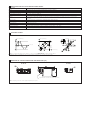
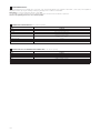
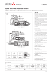
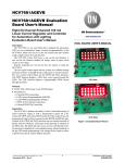
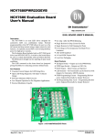
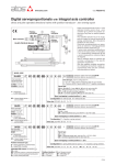
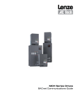
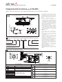
www.atos.com
Table G120-5/E
Integral electronic drivers type E-RI-AEG
digital, with cycle generator - for proportional directional valves without transducer
Power supply connector,
see section 쪬
RS232 communication
connector, see section 쪬
DHZO-AEG-PS-071-*
Speed
Forward
Position
Backwards
1
MODEL CODE: PROPORTIONAL VALVES WITH INTEGRAL DIGITAL DRIVERS TYPE E-RI-AEG
E-RI
-
A
EG - PS -
01H
**
/*
Integral electronic
driver
Set code (see note)
A = without transducer
Series number
EG = with integral digital electronic and cycle
generator
01H = for single solenoid proportional valves
05H = for double solenoid proportional valves
PS = serial RS232 communication
These digital drivers are integral to Atos proportional directional valves without transducer and they control the current to the solenoid, regulating the spool position proportionally to a digital programmed reference
signal.
Two modes of operation are available:
• Mode A: the driver automatically handles
forward/backward working cycles with fastslow speed control. The digital driver receives ON/OFF inputs from the local proximity
microswitches (f1...f4) and command
signals (start forward/backward) from the
machine control unit and thus activates the
corresponding cycle phase.
• Mode B: the driver actuates up to six different phases (speed + ramp), according to
the configuration of the ON-OFF command
signals on the supply connector. An external PLC may control the desired working
cycle by generating the command signals
to the digital driver.
Features:
• software setting of cycle configuration • integral digital electronics , factory preset
• configuration of the cycle's parameters
(speed, ramps) via RS232 serial communication interface
• software setting of the main functional
parameters as bias, scale, ramps, by
means of the relevant programming device
Kit-E-SW-PS, see section 쪯
• possibility to optimize the application
performance modifying via software the
internal parameters as the regulation characteristic of the valve (linearization)
• 12 pins power supply connector arranged to receive the power supply and the
ON-OFF input command signals for the
cycle generator
• 5 pins standard M12 connector dedicated to the serial RS232 connection with PC
• IP67 protection degree
• 3,3A maximum current to the coils
• CE marking granting the conformity to the
EMC Directive (Electromagnetic Compatibility)
Note: the set code identifies the corrispondance between the digital integral driver and the relevant valve.
2
ELECTRONIC AND WIRING BLOCK DIAGRAM
RS232
INTERFACE
OPTICAL
INSULATED INPUTS
MICROCONTROLLER
CYCLE
GENERATOR
BIAS
SCALE
LINEARIZATION
ALARM
POWER SUPPLY
CONNECTOR
RS232
CONNECTOR
COIL S2
COIL S1
SUPPLY CONNECTOR
1
2
3
4
5
6
7
8
9
10
11
PE
SIGNAL DESCRIPTION
Power supply 24 VDC
Power supply zero
Enable
TECHNICAL SPECIFICATION
Stabilized:
+24VDC
Filtered and rectified: Vrms = 21 ÷ 33 (ripple max 2 Vpp)
Not active: 0 VDC, connected to pin 2
Active: 24 VDC, optical isulated input (threshold 9,7V)
Floating: manual forward/backward movements possible
COMMAND SIGNALS
F1
F2
F3
Optical insulated input 0 ÷ 24 VDC
F4
(threshold 9,7 V) - referred to pin 10
F5 (Start Forward for Mode A)
F6 (Start Backward for Mode A)
ON/OFF GND
optical insulated input GND (ø V for F1÷F6)
Fault
Output 0 ÷ 24 VDC (max 30 mA)
Earth
Connect only when the power supply don’t conform to VDE 0551 (CEI 14/6)
Note: female plug connectors can be supplied separately on request
–PS (RS232)
NC
1
Not connected
NC
Pin number
Signal description
PIN
COMMUNICATION CONNECTOR
Communication
options
2
Not connected
RS_GND
3
Signal zero data line
RS_RX
4
Valve receiving data line
RS_TX
5
Valve transmitting data line
G120
3
MAIN CHARACTERISTICS OF E-RI-AEG ELECTRONIC DRIVERS
Driver section
Format
Sealed box on the valve - Protection: IP67 DIN 40050 - Insulation: VDE0110
Electromagnetic compatibility (EMC)
Emission: EN 50081-2 - Immunity: EN 50082-2
Max power consumption
50 W
Current supplied to solenoids
Imax = 3.3 A square wave PWM type
Operating temperature
-20°C ÷ +60°C (storage –20°C ÷ +70°C)
Features
Rapid solenoid excitation and switching off – Output to solenoids protected against accidental short circuits – Current control
by PI actions
Alarm messages
Electronic overcurrent, overtemperature, undertemperature, output stage fault
RS232 interface section (-PS option)
Serial input format
RS232C serial connection
Communication Protocol
Atos Protocol with ASCII coding
Programming Interface
Personal Computer with interface software for Windows ® (KIT-E-SW-PS see tab. G500)
Notes
KIT-E-SW-PS, supplied separately
4
AVAILABLE SETTINGS
UP AND DOWN RAMPS
LINEARIZATION
Valve regulation [%]
SCALE AND BIAS
Current [%]
Valve regulation [%]
Scale Setting
Bias Setting
Time [sec]
Bias Setting
Adjustable
regulation
characteristic
Reference [%]
Reference [%]
Scale Setting
Note: for a complete description of the software, see the user manual MAN-SW-PS/G included in the Kit-E-SW-PS
Note: dither frequency is available from 160 Hz to 500 Hz (home setting 200 Hz) - Consult our technical office
5
DIMENSIONS OF THE ELECTRONIC DRIVER AND CONNECTORS [mm]
SP-ZH-12P
SP-ZH-5P
only for double solenoid valves (E-RI-AEG-*-05H)
Note: female plug connectors can be supplied separately on request
6
MODE A
When Mode A is active, the driver automatically handles forward/backward
working-cycles with fast-slow speed control according to the programmed
cycle. The digital driver reads the signals from the local proximity microswitches (f1...f4) and from the ON/OFF command signals (start
forward/backward) and consequently activates the various phases
(speed + ramp).
The local proximity microswitches and the command signals are connected to the supply connector (F1...F6, Fig. 1).
The working cycle is thus self generated and actuated by the above
signals, in particular:
• start forward signal (connected to F5) activates the forward movement;
• microswitch signals (f1.... connected to F1....) sequence the forward
cycle phases;
• start backward signal (connected to F6) activates the backward movement.
• microswitch signals (...f4 connected to ...F4) sequence the backward
cycle phases;
Machine
control
unit
Start forward
Start backward
f2
f1
Speed
f3
f4
V1
Forward
R2
R1
V2
R3
Features:
• maximum total four phases selectable (forward plus backward); maximum three phases selectable for each direction;
• for each of the four phases the following parameters can be set (Fig. 2):
- speed regulation Vn: corresponding to the driving current and therefore to the valve opening;
- ramp time Rn: time for a 0÷100% speed step (Vn - Vn-1).
• automatic / on input start: for each direction (forward or backward) it is
possible to choose if the start movement of that direction is activated
automatically at the end of the previous phase or on input (F5 for Start
Forward, F6 for Start Backward);
• polarity: each proximity switch can be set as normally closed / normally
open;
• type: each proximity switch signal can be set as impulsive / continuous;
• diagnostic:
- actual phase, showing the active phase during the cycle;
- actual direction, showing the active direction during the cycle.
• input state, showing F1 ÷ F6 electrical state (ON/OFF)
• configurable direction with positive reference signal (P → A or P → B of
the valve)
f4
f1
Position
f2
f3
R6
R4
V5
R5
V4
Backwards
Fig.1
Speed
Next phase
Previous phase
Phase “n-1”
Phase “n” (n = 1…4)
Position
Fig.2
Activation of “n” phase
7
MODE B
When Mode B is active, the driver actuates up to six different phases
(speed + ramp), according to the configuration of the ON-OFF command signals on the supply connector.
An external PLC may control the desired working cycle by generating the
command signals to the digital driver. Therefore, this Mode of operation is
the same available with the Eurocard analog driver type E-ME-AC-05F/4R-4,
but with the important advantage that digital parameters assure easy,
repetitive and precise settings.
Features:
• maximum six reference signals selectable;
• for each of the six signals the following parameters can be set (Fig. 2):
- speed regulation Vn: corresponding to the driving current and therefore to the valve opening;
- ramp time Rn: time for a 0÷100% speed step (Vn - Vn-1)
• ramp Rstop: ramp time when no imput are selected (actuator stop)
• polarity: each proximity switch can be set as normally closed / normally
opened;
• diagnostic:
- actual phase, showing the active phase during the cycle;
- actual direction, showing the active direction during the cycle
• configurable direction with positive reference signal (P → A or P → B of
the valve)
• the operation processing of the different phases is based on the pin
priority: the phase associated to the pin with higher number is performed before the phases associated to pins with lower number.
Machine
control
unit
Speed
V3
V1
R3
R1
R4
V2
R2
V4
Rstop
R6
Rstop
Position
V5
Fig.1
Speed
Previous phase
Next phase
Phase “n-1”
Phase “n” (n = 1…6)
Position
Fig.2
Activation of “n” phase
G120
8
PROGRAMMING DEVICES
The functional parameters of the digital valves, as the bias, scale, ramp and linearization of the regulation characteristic, can be easily set and optimized
with graphic interface by using the following software programming devices suitable for standard PC:
KIT-E-SW-PS for electronics with RS232 interface (option -PS)
see tab. G500 for complete information about the programming device kits and for the PC minimum requirements.
The above programming device has to be ordered separately.
9
CONNECTORS CHARACTERISTICS to be ordered separately
CONNECTOR TYPE
POWER SUPPLY CONNECTOR
CODE
SP-ZH-12P
TYPE
Female straight circular socket plug 11 pins +PE
MATERIAL
Plastic reinforced with fiber glass
CABLE GLAND
PG16
LiYCY 10 x 0,14 mm2 (signal)
CABLE
LiYCY 3 x 1 mm2 (power)
to crimp
CONNECTION TYPE
DIN 43563
STANDARD
IP 65
PROTECTION ACCORDING TO DIN 40050
10
CHARACTERISTICS OF COMMUNICATION CONNECTORS (to be ordered separately)
CONNECTOR TYPE
CODE
TYPE
MATERIAL
CABLE GLAND
CABLE
CONNECTION TYPE
STANDARD
PROTECTION (DIN 40050)
03/05
RS232 CONNECTOR (-PS)
SP-ZH-5P
Female straight circular socket plug 5 pins
Plastic
PG9
CANBus Standard (301 DSP)
screw terminal
M12 – IEC 60947-5-2
IP 67