1
Virtual Label Switching Router
Implementation Guide
Version 2.1b
April 2008
DRAGON
University of Southern California (USC)
Information Sciences Institute (ISI)
University of Maryland (UMD)
Mid-Atlantic Crossroads (MAX)
George Mason University (GMU)
http://dragon.east.isi.edu
VLSR Implementation Guide v2.1b
April 2008
Table of Contents
Summary........................................................................................................................................................................1
1
Introduction..........................................................................................................................................................2
1.1
Background ................................................................................................................................................2
1.2
Sample Configuration.................................................................................................................................2
1.3
Advanced Topics
.......................................................................................................................3
1.4
Document Organization..............................................................................................................................3
2
DRAGON Control Plane Components ................................................................................................................4
2.1
VLSR..........................................................................................................................................................4
2.1.1
DRAGON OSPF-TE..............................................................................................................................4
2.1.2
DRAGON RSVP-TE .............................................................................................................................5
2.2
CSA ............................................................................................................................................................5
2.3
DRAGON NARB and RCE
......................................................................................................6
2.4
ASTB..........................................................................................................................................................7
3
Setting up the Environment for DRAGON Software...........................................................................................7
3.1
Preparation before Installation....................................................................................................................7
3.1.1
System Requirements ............................................................................................................................7
3.2
Software Requirements...............................................................................................................................8
3.3
NARB/RCE Server Pre-installation
..........................................................................................9
4
Configuring the Switch ........................................................................................................................................9
5
DRAGON VLSR Software Installation Guide ..................................................................................................10
5.1
Basic Installation ......................................................................................................................................10
5.2
Advanced Installation
.............................................................................................................11
6
DRAGON Configuration Example ....................................................................................................................12
6.1
Setting up the GRE Tunnels .....................................................................................................................12
6.2
Configuration Guide .................................................................................................................................14
6.3
DRAGON OSPF-TE Configuration Guide .............................................................................................14
6.4
DRAGON RSVP-TE configuration Guide...............................................................................................16
6.5
DRAGON Configuration Guide ...............................................................................................................16
6.6
ZEBRA Configuration Guide ...................................................................................................................17
6.7
NARB/RCE Configuration Guide
...........................................................................................18
6.8
Running the Daemons ..............................................................................................................................18
6.8.1
ZEBRA Daemon..................................................................................................................................18
6.8.2
DRAGON OSPF-TE Daemon .............................................................................................................18
6.8.3
DRAGON RSVP-TE Daemon.............................................................................................................19
6.8.4
DRAGON Daemon..............................................................................................................................19
6.8.5
NARB/RCE Server
............................................................................................................19
6.9
Provisioning via DRAGON Command Line Interface (CLI)...................................................................19
7
Advanced Features
............................................................................................................................19
7.1
VLAN Based Ethernet Circuits ................................................................................................................20
7.2
VLSR-to-VLSR (Local ID) Based Provisioning ......................................................................................20
7.3
DRAGON UNI Provisioning....................................................................................................................21
7.4
Advanced Configuration Guide
..............................................................................................21
7.4.1
NARB/RCE and Inter-domain Environment Configuration................................................................21
7.4.2
Intermediate VLSR Configuration.......................................................................................................21
7.4.3
Ingress/Egress VLSR Configuration....................................................................................................23
7.4.4
Ingress/Egress End System Configuration...........................................................................................26
7.4.5
Provisioning via DRAGON UNI .........................................................................................................26
7.4.6
VLSR-to-VLSR (Local-ID) Based Provisioning .................................................................................27
8
Linux Software Switch Configuration
..............................................................................................27
9
Ethernet-over-SONET Subnet Configuration
...................................................................................28
9.1
OSPF-TE Configuration for Subnet ETTP Interfaces ..............................................................................28
9.2
OSPF-TE Configuration for Subnet Intermediate Links ..........................................................................29
9.3
DRAGON CLI Based Provisioning..........................................................................................................30
ii
VLSR Implementation Guide v2.1b
April 2008
10 Conclusion .........................................................................................................................................................30
11 DRAGON Project ..............................................................................................................................................31
Appendix A: Acronyms and Abbreviations...............................................................................................................32
Appendix B: Optional DRAGON CLI Commands ...................................................................................................33
Appendix C: References ............................................................................................................................................35
iii
VLSR Implementation Guide v2.1b
April 2008
Summary
This document provides a description of VLSR software implementation as a part of the DRAGON software suite. It
includes a discussion of the software components, installation instructions, and configuration guides. The presented
materials are intended for both the beginning users to gain initial hand-on experience and the advanced users and
developers to deal with more generic and complicated networking scenarios. Sample network configurations will be
provided in the description so as to facilitate better understanding of the implementation and installation. The
software has been implemented on both Linux and FreeBSD and the code has been successfully compiled under
several versions of GNU GCC/G++.
1
VLSR Implementation Guide v2.1b
April 2008
1 Introduction
This section provides a brief background on the Dynamic Resource Allocation in GMPLS Optical Networks
(DRAGON) project and general use of DRAGON software.
1.1 Background
The DRAGON project, funded by the National Science Foundation (NSF), is concerned with the research and
development of dynamic, deterministic, and manageable end-to-end network transport services for high-end eScience applications [1].
For its implementation, DRAGON deploys the IP network infrastructure and creates a Generalized Multi-Protocol
Label Switching (GMPLS) capable optical core network to allow dynamic provisioning of deterministic network
paths in direct response to end-user requests, spanning multiple administrative domains. Optical transport and
switching equipment acting as Label Switching Routers (LSRs) provide deterministic network resources at the
packet, wavelength, and fiber cross-connect levels. The all-optical capabilities is based on connection and resource
management mechanisms defined in GMPLS and the network models many of the functions of an inter-regional,
national, or even global wavelength based Research and Education (R&E) networks.
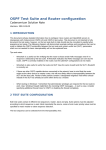
The basic objective of this document is to describe the installation and use of DRAGON software in order to set up
the capability in a network to dynamically provision dedicated paths across the network for high end application
such as high definition video or high volume low latency scientific data flows. This is accomplished through the
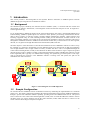
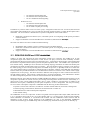
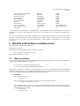
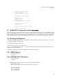
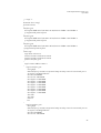
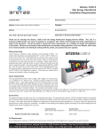
Virtual Label Switching Router (VLSR), as described later in details in this document. Figure 1 depicts the general
network topology where a number of VLSRs, constructed using Ethernet switches and DRAGON software, provide
traffic engineered paths. Typically on a GMPLS-based topology, the dynamically provisioned path is on an edgenode to edge-node base. However, if the DRAGON software is running at the end systems, the path can be
established on an end-to-end basis.
VLSR
S/W
VLSR
S/W
VLSR
VLSR
VLSR
S/W
VLSR
S/W
VLSR
S/W
VLSR
S/W
End
Sys
End
Sys
VLSR
VLSR
VLSR
VLSR
End
Sys
End
Sys
Figure 1: General diagram for VLSR deployment
1.2
Sample Configuration
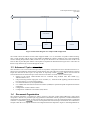
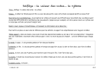
We will describe the installation and use of DRAGON software by illustrating the implementation in a minimum
sample case. The sample configuration establishes the Label Switched Paths (LSPs) between GMPLS-enabled hosts
through a special host without the GMPLS capability, providing end-to-end GMPLS-based services. This special
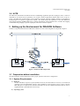
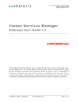
host is referred to as the Virtual Label Switching Router (VLSR). Here we install the DRAGON software on three
machines where one of these machines will be the control machine (VLSR) which will have a control over the
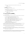
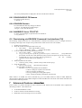
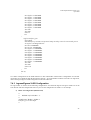
switch. The basic block diagram is depicted in Figure 2.
2
VLSR Implementation Guide v2.1b
April 2008
Control (Switch hub)
Control Machine
Node/host
Switch
Node/host
Figure 2: Basic block diagram of a sample VLSR configuration
The VLSR controls an Ethernet switch (which supports SNMP v1 or v2) and makes it capable of label switching.
This is made possible with the help of Net-SNMP and DRAGON software installed on the VLSR. Meanwhile,
Generic Routing Encapsulation (GRE) tunnels are set up from the hosts to the VLSR and from the VLSR to the
hosts. In this way the data plane and the control plane are separated as illustrated in the Figure above. The LSPs can
then be set up between any two hosts through the VLSR.
1.3 Advanced Topics
This document covers several advanced topics that are beyond the configuration we have described in Section 1.2.
These topics are intended for advanced users and developers who work with more complicated networking scenarios.
will be used to mark the
People not interested in these topics can skip them. A superscript notation
sections that discuss the advanced topics in this document. The below is a brief overview of these topics.
• Support of the switch vendors/models that are controlled using methods other than SNMP (e.g.,
TELNET/SSH or TL1)
• LSP provisioning between edge ports of two switches (i.e., VLSR-to-VLSR signaling) instead of between
two end systems (i.e., host-to-host signaling)
• User-Network Interface (UNI) implementation
• Use of DRAGON Network Aware Resource Broker (NARB) for sophisticated path computation and traffic
engineering
• Configuration of Linux software switch
• Configuration of Ethernet-over-SONET (EoS) subnet
1.4
Document Organization
The remaining document is organized as follows. Section 2 describes VLSR related DRAGON control plane
components. Sections 3-9 provide step-by-step guidelines to DRAGON network preparation, VLSR installation and
configuration, and VLSR running. In each section, there are portions that cover the advanced materials as mentioned
in Section 1.3 (marked by
). Section 10 incorporates these advanced topics and features into an illustrative
example which has more sophisticated network configuration than that depicted in Figure 2. Detailed guidelines for
3
VLSR Implementation Guide v2.1b
April 2008
advanced configurations are provided in Section 11. Sections 12 and 13 are dedicated to two special types of VLSR
configurations that control Linux software switches and Ethernet-over-SONET subnets respectively.
2 DRAGON Control Plane Components
The DRAGON architecture utilizes Generalized MultiProtocol Label Switching (GMPLS) as the basic building
block for network element control and provisioning. There are several key functional elements identified in the
DRAGON control plane architecture:
•
•
•
•
Virtual Label Switch Router (VLSR)
Network Aware Resource Broker (NARB)
Client System Agent (CSA)
Application Specific Topology Builder (ASTB)
There are two main modes of provisioning dynamic services (i.e., circuits):
• CSA-to-CSA
• VLSR-to-VLSR
Both of these will be described in more detail in this document.
A more detailed description of the control plane architecture and these components is presented in [2]. A high level
description is provided in the sections that follow. This document focus is on the VLSR and CSA which is
constructed using the same software package. Information on how to download, compile, configure and install the
VLSR and CSA is included in this document. Other documents are referenced for details on the NARB and ASTB.
2.1 VLSR
The VLSR provides a mechanism to integrate non GMPLS equipment and network regions into the end-to-end
GMPLS provisioned services. The VLSR translates standard GMPLS protocols into device specific protocols, to
allow dynamic reconfiguration of non-GMPLS aware devices. The combination of a PC which runs the GMPLS
based control plane software and a switch fabric is referred to as a VLSR. The VLSR PC consists of a control plane
stack which includes OSPF-TE [3] and RSVP-TE [4] and acts as a proxy agent for the non-GMPLS capable devices.
This allows non-GMPLS devices to be included in end-to-end path instantiations. The primary use for VLSR on the
DRAGON project is to control Ethernet switches via the GMPLS control plane. However, the VLSR has also been
adapted to control TDM and Optical switches.
Our application of the VLSR to Ethernet environments has included modifications to OSPF-TE and RSVP-TE to
allow the provision of Ethernet circuits based on VLAN configurations [5]. At each Ethernet switch, the VLSR
translates RSVP-TE signaling messages into local switch commands and creates the desired VLAN-ports
associations along with the requested bandwidth guarantees. Whenever an Ethernet circuit (or LSP) is set up or torn
down, the bandwidth and VLAN tag information is updated via distribution of OSPF-TE Link State Advertisements
(LSAs) in order to maintain proper link states across the network. The VLSR PC uses a combination of RFC
2674[6] SNMP and Command Line Interface (CLI) commands for local control of the Ethernet switch fabric.
Additional details on the VLSR OSPF-TE and RSVP-TE implementations are provided below.
2.1.1 DRAGON OSPF-TE
OSPF is a link-state routing protocol developed for the IP networks. OSPF sends Link State Advertisements (LSAs)
to all other routers within the same area. Each OSPF router maintains an identical database describing the network
topology. From this database, a routing table is calculated by constructing a shortest path tree. In other words, the
OSPF routers accumulate Link State information and use the SPF algorithm to calculate the shortest path to each
node. OSPF recalculates routes quickly in the face of topological changes, utilizing a minimum of routing protocol
traffic. OSPF also carries the link state information for the GMPLS. It includes the OSPF TE. The Constraint
Shortest Path First (CSPF) module is provided as a separate module which includes an Application Programming
4
VLSR Implementation Guide v2.1b
April 2008
Interface (API) in the form of function calls and provides the ability to compute the traffic engineered paths based
on the OSPF-TE derived Link State Database (LSDB).
The DRAGON project has extended the open source GNU Zebra [7] routing software package to include required
GMPLS functionality. The GNU Zebra distribution is a routing protocol suite and includes multiple network
protocols such as RIP, OSPF, BGP and others. The DRAGON OSPF-TE software is extended from the GNU Zebra
OSPF daemon module and understands how to interpret those LSDB data structures. The current CSPF
implementation is limited to a single network region (or layer) and considers the standard GMPLS TE constraints of
bandwidth availability and interface switching capability. The DRAGON modifications included the following:
•
•
•
Addition of GMPLS TE extensions for OSPF
Configuration and origination of TE LSAs for VLSR-VLSR data links
Incorporation of CSPF routing module in support of Layer-2 constraints (e.g., using continuous end-to-end
VLAN tags)
2.1.2 DRAGON RSVP-TE
RSVP is a signaling protocol that allows the sender and receiver in a communication to set up a reserved highway
for data transmission with a specified Quality of Service (QoS). Applications running on IP end systems can use
RSVP to indicate to other nodes the nature (e.g. bandwidth) of the packet streams they want to receive.
The DRAGON project has extended the open source KOM RSVP Engine [8] from the Technical University of
Darmstadt to include required GMPLS TE functionality. The KOM RSVP Engine provides an implementation of
RSVP. The DRAGON modifications include the following:
•
•
•
•
•
Addition of GMPLS TE extensions for RSVP
Extension of the KOM-RSVP API to pass the VLSR specific configurations to the RSVP daemon
Addition of functionality to allow control of Ethernet switches via SNMP and other methods
Addition of functionality to allow control of EoS subnets via TL1
Support of VLSR-to-VLSR signaling (the so called DRAGON Local ID feature), continuous end-to-end
)
VLAN and DRAGON UNI features (elaborated later
2.2 CSA
The CSA is software that runs on (or on behalf of) any system which terminates the data plane (traffic engineering)
link of the provisioned service. This is the software that participates in the GMPLS protocols to allow for ondemand end-to-end provisioning from client system to client system. In this context, Client System (CS) is a very
broad term. It generally means any device which finds it self on the edge of a DRAGON enabled dynamically
provisioned network. This could include a host, a computational cluster, a router, a radio telescope, and various
other networked devices. In this context, a "client" is any system which is requesting network services. Previous
documentation referred to the CSA as the End-System Agent (ESA). This has been changed to CSA to reflect the
more general nature of client systems which may request network services. The CSA typically runs in peer-to-peer
mode, overlay mode via a UNI protocol, or a web service mode. The CSA may also interact with the ASTB if a
more complicated topology is to be built.
The DRAGON architecture identifies three distinct types of CSA modes of operation:
•
Peer-to-Peer CSA
o CS terminates the data plane link
o CS terminates the control plane link
o CS has both RSVP and OSPF
Note: in this mode of operation, the CSA looks very much like a VLSR. A distinction is made
here based on the anticipated use of a client system with this configuration in place.
•
UNI CSA
5
VLSR Implementation Guide v2.1b
April 2008
o
o
o
•
CS terminates the data plane link
CS terminates the control plane link
CS use UNI (RSVP based) Signaling
WebService CSA
o CS terminates the data plane link
o CS terminates the control plane link
o CS use XML to request provisioning
In addition any of these modes can be run in the "proxy" configuration where the CSA is located (and associated
control plane link terminated) on a proxy box which is physically separate from the CS where the data plane link is
terminated. The CSA software is instantiated via a specific configuration of the VLSR software.
•
•
DRAGON Command Line Interface (CLI) commands specific for configuring VLSR-specific parameters
on RSVP daemon.
Support of DRAGON Local ID and DRAGON UNI features (elaborated later
)
The main CSA features relevant to VLSR include the following:
•
•
•
KOM-RSVP API to initiate or remove an RSVP session to the RSVP daemon.
DRAGON Command Line Interface (CLI) commands specific for configuring VLSR-specific parameters
on RSVP daemon.
)
Support of DRAGON Local ID and DRAGON UNI features (elaborated later
2.3 DRAGON NARB and RCE
NARB is an entity that represents the local Autonomous System (AS) or domain. The NARB serves as path
computation engine from which end-systems or other devices can query to find out about availability of traffic
engineered paths between specified source and destination pairs. A stand-alone subcomponent of the NARB called
the Resource Computation Element (RCE) performs the path computation tasks. The NARB is also responsible for
inter-domain routing. NARBs peer across domains and exchange topology information to enable inter-domain path
computation and Label Switched Path (LSP) provisioning. This inter-domain topology exchange can be based on
the actual topology as discovered by listening to the local OSPF-TE protocol, or optionally based on an "abstracted"
view of the domain topology (generated by configuration file or automatic synthesis of the OSPF link state database).
Domain abstraction provides mechanisms for an administrative domain to advertise to the outside world a highly
simplified view of its topology. This allows domains to hide their real topologies as well as minimize the amount of
external updates required. The trade-off is reduced accuracy for path computations. Each administrative domain
can utilize configuration parameters to tailor its domain abstraction to the level desired.
DRAGON Network Aware Resource Broker (NARB) and DRAGON Resource Computation Element (RCE) are the
components responsible for network resource provisioning and management. Because the RCE functionality is a
coherent part of the overall NARB functionality, RCE is often considered a subcomponent of NARB. In the
DRAGON control plane, NARB/RCE provides path computation, resource management, and LSP provisioning
services to other control plane components. NARB/RCE has the following VLSR related features:
•
•
•
•
Dynamic resource state collection (via both intra- and inter-domain OSPF-TE) and resource management
Domain topology summarization, abstraction and advertisement via OSPF-TE
Multi-dimensional constraint based path computation
Inter-domain routing
The NARB/RCE services are required for VLSR to be signaled with an Explicit Route Object (ERO) when the LSP
is (a) a continuous end-to-end VLAN, (b) an inter-domain path, (c) is created via the VLSR-to-VLSR signaling
and/or DRAGON UNI methods, or (d) attached with local-ids. The four NARB/RCE related scenarios will be
elaborated in later sections. People interested in the NARB/RCE can refer to the DRAGON NARB/RCE
Architecture document [9], the NARB Design and User Manual [10], and the RCE Design and User Manual [11].
6
VLSR Implementation Guide v2.1b
April 2008
2.4 ASTB
The DRAGON architecture includes the notion of establishing Application Specific Topologies (AST). These are
requested by an end user and are generally a set of LSP’s which an application domain desires to be set up as a
group. The DRAGON element known as the Application Specific Topology Builder (ASTB) is responsible for
coordinating this in response to application requests. The ASTB utilizes the capabilities of the other DRAGON
control plane elements (NARB,VLSR,CSA) to request instantiation of the individual LSP’s, maintain the mapping
of individual LSP groupings to specific topologies, and interact with user requests.
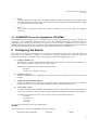
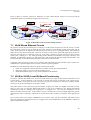
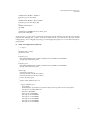
3 Setting up the Environment for DRAGON Software
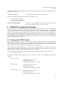
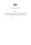
10.20.0.1
NIC
10.10.0.1
NIC
Control Line
Control Line
Control Line
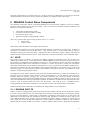
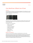
In order to set up the Environment for DRAGON software we refer to the configuration as depicted in Figure 3.
Figure 3: Sample VLSR configuration
3.1 Preparation before Installation
The following steps must be followed to achieve proper operation of the above configuration:
3.1.1 System Requirements
a) Hardware
At least 500 MHz of processor speed (Pentium III level) and 256 RAM are necessary to run both the
operating system and DRAGON software. After installation of the operating system, at least 1 GB free
hard disk space is required. Each machine should have at least two Ethernet network interfaces (Fast or
Gigabit Ethernet is preferable but not necessary).
b) Operating system
7
VLSR Implementation Guide v2.1b
April 2008
The hosts and VLSR control machines can run either Linux (kernel version 2.4.20 or above) or FreeBSD
(kernel version 4.11 or above), or a hybrid of Linux and FreeBSD. We have tested this software on
RedHat v9, RedHat Fedora Core 3 and 4, RedHat Enterprise Linux AS release 4, Debian 4.0, FreeBSD
4.11-RELEASE and 6.1-RELEASE.. Distributions with higher kernel versions should also work. In the
remaining document, the reference operating system in all examples will be Linux.
3.2 Software Requirements
The following software is required prior to installation of DRAGON software. A single file which contains this
software is available via the below link:
•
http://dragon.east.isi.edu/twiki/pub/Main/VLSR/dragon.dependencies.tar.gz
The package can be unpacked by typing the following commands:
#tar –zxf dragon.dependencies.tar.gz
The following commands will install the DRAGON dependency software:
#cd dependence-package
# ./makealldeps.sh
•
SSH
Ssh provides with a secure way to log in to the remote machine. One can move files from one machine to
another with secure communications over insecure channels. Somebody who has root access to machines
on the network, or physical access to the wire, can gain unauthorized access to systems in a variety of
ways. ssh is usually included in the Linux and FreeBSD installation package but if not, it can be installed
from ftp://ftp.net.ohio-state.edu/pub/security/ssh .
•
GNU Compilers
gcc/g++: We have compiled our software under the following GNU GCC/G++ versions: 2.95.x, 3.2.x,
3.4.x, and 4.0.x.
bison: bison is the GNU parser generator (yacc replacement) to parse the .y files.
flex: flex is a fast lexical analyzer generator to parse the .l files.
•
Net-SNMP
DRAGON software requires Net-SNMP for its installation. The sample case referred in this document
installs Net-SNMP version 5.1.1. It can be downloaded from: http://prdownloads.sourceforge.net/netsnmp/ .
Net-SNMP is a suite of applications used to implement SNMP v1, SNMP v2c, SNMP v3 using both IP v4
and IP v6. The suite includes Command Line application, a graphical MIB Browser, daemon application
for receiving SNMP notifications, an extensible agent for responding to SNMP queries for management
information and a library for developing new SNMP applications with both C and Perl APIs. All versions
of Net-SNMP are available at www.net-snmp.org/download .
•
SVN
Note: this is not needed if DRAGON software has been obtained/downloaded from other sources.
svn is a command used for subversion control which is an open source version control system. In
subversion, a tree of files is kept in the central repository. The repository remembers every change that is
ever made to the files and directory. This means that if an incorrect change has been made to the data, the
previous data is not lost because all the work is versioned. Thus, no matter how many changes are done to
a file, the original file as well all the other versions of the file can always be referenced at any time.
Subversion can be installed from the site, http://subversion.tigris.org .
8
VLSR Implementation Guide v2.1b
April 2008
•
libxml2
libxml2 is used to parse XML files. The DRAGON daemon software needs this library to support XMLdescribed application specific topology provisioning. It must be compiled with the libxml2 library though
the feature may be irrelevant to VLSR.
•
zlib-1.2.3
zlib is used to compress/uncompress data which is contained in some of the routing and signaling
protocols.
3.3 NARB/RCE Server Pre-installation
The NARB/RCE server software runs on a standalone PC. The system requirements are the same as described in
Section 3.1.1. The recommended operating system is Linux. In a multi-domain network, each domain needs one
NARB/RCE server that has IP connectivity to at least one VLSR in the domain. NARB/RCE servers in adjacent
domains should have IP connectivity to each other. More information about the NARB/RCE network environment is
provided in the NARB Design and User Manual [10] and the RCE Design and User Manual [11].
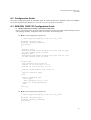
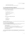
4 Configuring the Switch
The switch (which supports Net-SNMP) is now connected to all the three machines. The VLSR will control the
switch and so it is important to configure it. Go through the instruction manual for the switch and follow the
instructions. The below is a checklist for items concerning the VLSR when configuring the switch.
a.
Configure SNMP server
The SNMP server must be enabled on the VLSR switch. Add a ‘dragon’ community to the SNMP server.
The community should have both read and write privileges.
On Dell PowerConnect 5324, for example, do the following:
#configure
# snmp-server community dragon rw
b. Configure access list
For those switches that have configured an access list (or firewall), open the access to the VLSR control
machine.
c.
Assign and record administration IP
Assign an IP address to the control interface facing the VLSR control machine on the switch. It is important
to keep a record of it since we will need to add this IP into some configuration file later on.
d. Create empty VLANs
For those switches that use the SNMP control method but do not support dynamic creation and deletion of
VLAN, we need to create empty VLANs bearing the tags that are possibly be used in future provisioning.
On Dell PowerConnect 5324, if we want to use the VLANs 100 and 200, do following:
#configure
# vlan database
# vlan 100
# vlan 200
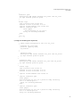
The remaining section is for advanced users.
The current release of VLSR code supports the following switches.
Dell PowerConnect 5224/5324
:
RFC2674
:
SNMP
9
VLSR Implementation Guide v2.1b
April 2008
Dell PowerConnect 6024/6024F
Extreme Summit 1i/5i
Intel Express 530T
Raptor ER1010
Cisco Catalyst3750
Cisco Catalyst6550
HP 5406
SMC10G8708
Force10 E300/E600
Linux Software Switch
EoS Subnet
:
:
:
:
:
:
:
:
:
:
:
RFC2674
RFC2674
IntelES530
RaptorER1010
Catalyst3750
Catalyst6550
HP5406
SMC 10G 8708
Force10E600
LinuxSwitch
N/A
:
:
:
:
:
:
:
:
:
:
:
SNMP
SNMP
SNMP
SNMP
SNMP
SNMP
SNMP
SNMP
CLI (SSH/TELNET)
Shell/SSH/TELNET
TL1
The nomenclature is { Switch Name : Vendor/Model ID : Control Method }. The Vendor/Model ID is to be used to
configure the VLSR such that appropriate code module can be loaded to some vendor/model specific switch
behaviors.
To use the CLI (TELNET or SSH) control method, a user account should be created on the switch. This account
should have sufficient privilege to execute commands such as creation of VLAN and moving ports to/from VLAN.
Note that even if CLI is used as the control method for a switch, SNMP is still needed to ‘read’ the switch
information.
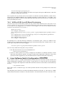
5 DRAGON VLSR Software Installation Guide
The VLSR software can be downloaded from:
http://dragon.east.isi.edu
The package can be unpacked by typing the following commands:
#tar –zxf dragon-sw-snapshot.xxxx.tar.gz
(see web site for latest "xxxx" values)
5.1
Basic Installation
Now enter the working directory where the DRAGON package has been unpacked or checked out. The following
commands will install the DRAGON software:
# ./do_build.sh to configure and build the package
# sudo sh do_install.sh to install the DRAGON Software
By default the software gets installed at /usr/local/dragon. If you wish to use the normal step-by-step installation
method, the following takes care of installing the DRAGON Software including KOM-RSVP (DRAGON RSVPTE) and GNU ZEBRA (including DRAGON OSPF-TE and dragon daemon).
a) KOM-RSVP:
Enter the kom-rsvp directory,
#cd kom-rsvp
The kom-rsvp code is then configured. (Just hit return when prompted for input.)
#. /configure –-with-snmp=/usr/local
This command configures kom-rsvp with snmp provided net-snmp header files are installed at /usr/local
else it is important to specify the correct pathname. After configuration is done, the directory is cleaned and
the file dependencies are rebuilt:
# gmake clean
# gmake depend
10
VLSR Implementation Guide v2.1b
April 2008
Finally, the code is recompiled and the new binaries and libraries are installed for system,
# gmake
# sudo gmake install
b) GNU ZEBRA:
The OSPF can be installed as follows:
Enter the directory zebra under the dragon-sw directory,
# cd zebra
Configure the protocol by typing the following command. The prefix command defines the directory
where ZEBRA-OSPF should be installed.
#. /configure --prefix=/usr/local/dragon –-enable-dragon
Finally, compile the code and install the files,
# make
# sudo make install
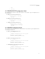
5.2 Advanced Installation
You can provide a target option to customize the software building.
# ./do_build.sh [target]
The build option [target] tells what kind of control entity to build. The control entity could be one of the following.
vlsr -- A generic VLSR that uses automatic probe to determine switch type.
vlsr-verbose -- Building a VLSR with user's interactive input.
vlsr-force10 -- Building a VLSR that operates on Force10 E300/E600 switch
vlsr-force10-v6 – Building a VLSR that operates on Force10 switch with software version 6.x.x.x
vlsr-raptor – Building a VLSR that operates on Raptor E1010 switch
vlsr-cat3750 (-cat6550) – Building a VLSR that operates on Cisco Catalyst3750 (or 6550) switch
vlsr-linux – Building a VLSR that uses local Linux host as an emulated software switch
vlsr-subnet – Building a VLSR that operates on Ethernet-over-SONET subnet
csa – Building a Client System Agent
narb -- Building supporting software components for NARB sever.
Without the [target] option, the default option will be vlsr.
By default, this software gets installed at /usr/local/dragon. You can change the installation directory by setting the
environment variable $DRAGON_PREFIX before running the do_build.sh and do_install.sh scripts.
The following further provides guide on the step-by-step installation. When running the ./configure script with the –
with-snmp option for the DRAGON RSVP-TE (KOM-RSVP), one is prompted for inputting two parameters.
Switch Vendor/Model number (Default: AutoDetect):
One can provide the Vendor/Model ID (e.g., Force10E600, RaptorER1010, etc.) as defined in Section 4.0 if it is
known. Otherwise, return to use AutoDetect so that the VLSR will determine the switch vendor/model type
automatically by querying system description via SNMP.
Switch control port to use (Default: 255):
The switch control port is the switch port (e.g., port 1 for some switches) used to connect the switch to the control
network. If the switch control port is moved as a data plane port, the switch will be cut off from the control plane.
One can specify the switch control port in order to avoid this port from moving as a data plane port.
11
VLSR Implementation Guide v2.1b
April 2008
The DRAGON RSVP-TE (KOM-RSVP) software has the following optional pre-compilation configuration options
in addition to –with-snmp.
--enable-switch-cli-access
configures the VLSR to use the CLI control method.
It prompts for inputting username, password and CLI type (telnet or ssh).
Username (Default: unknown):
Password (Default: unknown):
CLI Session Type (Default: none):
--enable-switch-port-shutdown
6
enforces the switch to shutdown a switch data port when it is removed
from a VLAN and does not exist in any other VLAN.
DRAGON Configuration Example
This section provides a configuration example based on the topology shown in Figure 3. This is a simple topology
consisting two end systems (Host 1 and Host 2) connected to one Ethernet switch based VLSR. The DRAGON
software running on Host 1 and Host 2 are what is referred to as CSA (Client System Agents) in the previous
sections. The configuration example that follows is an example of the Peer-to-Peer CSA mode configuration. As
mentioned earlier, from a DRAGON software configuration perspective this very similar to a VLSR configuration.
The main distinction being that the Host1 and Host2 do not have edge ports or a switch fabric to interconnect
multiple dataplane ports like an Ethernet switch based VLSR would have. The specific case of VLSR-to-VLSR
provisioning will be addresses in Section 7.
6.1 Setting up the GRE Tunnels
Encapsulation takes packets or frames from one network system and places them inside frames from another
network system. This method is sometimes called tunneling. Tunneling provides a means for encapsulating packets
inside a routable protocol via virtual interfaces. Tunneling allows any control plane protocol to be transmitted in a
virtual network over a physical network which is running on some other protocol.
In the example network depicted in Figure 3, we need to set up two GRE tunnels. One from host 1 to the control
machine (VLSR) called gre1 and the other from host 2 to control machine (VLSR) called gre2. The routing and
signaling messages can then be passed the GRE tunnels from host 1 to host 2.
In the Linux system, the following command is needed to load the GRE tunnel module into the Linux kernel.
# /sbin/modprobe ip_gre
To explain the set up of GRE tunnel between host 1 and control machine we have assumed the following IP
addresses:
Host 1 (cnl_host1):
Network address: 129.174.43.90
Netmask: 255.255.255.0
Local address of interface gre1: 10.10.0.1
Host 2(cnl_host2):
Network address: 129.174.42.221
Netmask: 255.255.255.0
Local address of interface gre2: 10.20.0.1
Control machine (cnl_vlsr):
Network address: 129.174.42.12
Netmask: 255.255.255.0
Local address of interface gre1: 10.10.0.2
12
VLSR Implementation Guide v2.1b
April 2008
Local address of interface gre2:10.20.0.2
a) Host 1: On the host 1, the following takes place:
/sbin/ip tunnel add gre1 mode gre remote 129.174.42.12 local
129.174.43.90 ttl 255
/sbin/ip link set gre1 up
/sbin/ip addr add 10.10.0.1 dev gre1
/sbin/ip route add 10.10.0.0/24 dev gre1
The explanation of each of the command lines above is as follows:
ip tunnel add gre1 mode gre remote 129.174.42.12 local 129.174.43.90 ttl 255
In this command we have added a tunnel device called gre1. This tunnel device uses the GRE protocol
mode gre. The remote address is 129.174.42.12. The tunneling packets should originate from
129.174.43.90 which is the address of the router of the host 1 at the control machine end. The TTL field of
packet is set to 255.
ip link set gre1 up
This command enables the device.
ip addr add 10.10.0.1 dev gre1
The interface gre1 has been given an IP address 10.10.0.1.
ip route add 10.10.0.0/24 dev gre1
Now a route is added to the control machine with IP address 10.10.0.0.
b) Host 2: Similarly, on the host 2 we will set up a GRE tunnel from host 2 to the control machine.
/sbin/ip tunnel add gre2 mode gre remote 129.174.42.12 local
129.174.42.221 ttl 255
/sbin/ip link set gre2 up
/sbin/ip addr add 10.20.0.1 dev gre2
/sbin/ip route add 10.20.0.0/24 dev gre2
c)
VLSR: Finally, the GRE tunnel is linked to the VLSR as follows,
/sbin/ip tunnel add gre1 mode gre remote 129.174.43.90 local
129.174.42.12 ttl 255
/sbin/ip link set gre1 up
/sbin/ip addr add 10.10.0.2 dev gre1
/sbin/ip route add 10.10.0.0/24 dev gre1
/sbin/ip tunnel add gre2 mode gre remote 129.174.42.221 local
129.174.42.12 ttl 255
/sbin/ip link set gre2 up
/sbin/ip addr add 10.20.0.2 dev gre2
/sbin/ip route add 10.20.0.0/24 dev gre2
In case the GRE tunnel is not set right, it can be removed as follows,
#/sbin/ip link set gre1 down
#/sbin/ip tunnel del gre1
The remaining section is for advanced users.
Additional GRE tunnels are needed for running the NARB/RCE server. Detailed configuration guidelines are
available via the DRAGON NARB User Manual [11].
13
VLSR Implementation Guide v2.1b
April 2008
6.2 Configuration Guide
The sample configuration guides for DRAGON OSPF-TE, DRAGON RSVP-TE, DRAGON daemon and ZEBRA
for the case illustrated in this document i.e. cnl_host1--cnl_vlsr--cnl_host2 are as follows:
6.3 DRAGON OSPF-TE Configuration Guide
i) Modify ospfd.conf on an client systems (hosts) and VLSR
Here, we specify hostname, password, GRE tunnel interfaces between hosts and VLSR and finally router id
and switching capability. Configuration files are located in /usr/local/dragon/etc.
a) Host 1 (/usr/local/dragon/etc/ospfd.conf):
!
! zebra-ospfd configuration file for cnl_host1
!
hostname cnl_host1-ospf
password [specify password]
log stdout
!
!
interface gre10
description GRE tunnel between cnl_host1 and cnl_narb
ip ospf network point-to-point
interface gre1
description GRE tunnel between cnl_host1 and cnl_vlsr
ip ospf network point-to-point
!
!
router ospf
ospf router-id 129.174.43.90
network 10.1.0.0/24 area 0.0.0.0
network 10.10.0.0/24 area 0.0.0.0
!
ospf-te router-address 129.174.43.90
!
ospf-te interface gre10
exit
!
ospf-te interface gre1
level gmpls
data-interface ip 10.1.10.2
swcap lsc encoding Ethernet
exit
!
line vty
!
b) Host 2 (/usr/local/dragon/etc/ospfd.conf):
!
! zebra-ospfd configuration file for cnl_host2
!
hostname cnl_host2-ospf
password [specify password]
log stdout
!
14
VLSR Implementation Guide v2.1b
April 2008
!
interface gre2
description GRE tunnel between cnl_host2 and cnl_vlsr
ip ospf network point-to-point
!
!
router ospf
ospf router-id 129.174.42.221
network 10.20.0.0/24 area 0.0.0.0
ospf-te router-address 129.174.42.221
ospf-te interface gre2
level gmpls
data-interface ip 10.1.20.2
swcap lsc encoding Ethernet
exit
!
line vty
!
c) VLSR (/usr/local/dragon/ec/ospfd.conf)
!
! zebra-ospfd configuration file for cnl_vlsr
!
hostname cnl_vlsr-ospf
password [specify here]
log stdout
!
!
interface gre1
description GRE tunnel between cnl_vlsr and cnl_host1
ip ospf network point-to-point
!
!
interface gre2
description GRE tunnel between cnl_vlsr and cnl_host2
ip ospf network point-to-point
!
!
router ospf
ospf router-id 129.174.42.12
network 10.10.0.0/24 area 0.0.0.0
network 10.20.0.0/24 area 0.0.0.0
!
ospf-te router-address 129.174.42.12
!
ospf-te interface gre1
level gmpls
data-interface ip 10.1.10.1 protocol snmp switch-ip
10.1.1.2 switch-port 9
swcap lsc encoding Ethernet
exit
!
ospf-te interface gre2
level gmpls
data-interface ip 10.1.20.1 protocol snmp switch-ip
10.1.1.2 switch-port 10
swcap lsc encoding Ethernet
15
VLSR Implementation Guide v2.1b
April 2008
exit
!
line vty
!
6.4 DRAGON RSVP-TE configuration Guide
This configuration file specifies the GRE tunnel interfaces of the machine. Copy the configuration file to
/usr/local/dragon/etc.
a) Host 1 (/usr/local/dragon/etc/RSVPD.conf):
!
interface gre1 tc none mpls
api 4000
!
b) Host 2 (/usr/local/dragon/etc/RSVPD.conf):
!
interface gre2 tc none mpls
api 4000
!
c) VLSR (/usr/local/dragon/etc/RSVPD.conf):
!
interface gre1 tc none mpls
interface gre2 tc none mpls
api 4000
!
6.5 DRAGON Configuration Guide
This configuration file specifies the hostname and the password for every machine. Copy the configuration file to
/usr/local/dragon/etc/dragon.conf.
a) Host 1 (/usr/local/dragon/etc/dragon.conf):
! -*- dragon -*!
! DRAGON configuration file for cnl_host1
!
hostname cnl_host1-dragon
password [specify password here]
b) Host 2 (/usr/local/dragon/etc/dragon.conf):
! -*- dragon -*!
! DRAGON configuration file for cnl_host2
!
hostname cnl_host2-dragon
password [specify password here]
c)
VLSR (cnl-vlsr) (/usr/local/dragon/etc/dragon.conf):
! -*- dragon -*!
! DRAGON configuration file for cnl_host2
!
hostname cnl_vlsr-dragon
password [specify password here]
16
VLSR Implementation Guide v2.1b
April 2008
6.6 ZEBRA Configuration Guide
ZEBRA is a daemon that services the OSPF daemon. It does not contain any DRAGON additions. Copy the
configuration file to /usr/local/dragon/etc
a) Host 1 (/usr/local/dragon/etc/zebra.conf):
! -*- zebra -*!
! zebra configuration file for cnl_host1
!
hostname cnl_host1-zebra
password [specify password]
! enable password [specify password]
!
! Interface description.
!
interface lo
interface gre1
interface gre10
! description test of desc.
!
!interface sit0
! multicast
!
! Static default route sample.
!
!log file zebra.log
b) Host 2 (/usr/local/dragon/etc/zebra.conf):
! -*- zebra -*!
! zebra configuration file for cnl_host2
!
hostname cnl_host2-zebra
password [specify password]
! enable password [specify password]
!
! Interface's description.
!
interface lo
interface gre2
! description test of desc.
!
!interface sit0
! multicast
!
! Static default route sample.
!
!log file zebra.log
c)
VLSR (/usr/local/dragon/etc/zebra.conf):
! -*- zebra -*!
! zebra configuration file for cnl_vlsr
17
VLSR Implementation Guide v2.1b
April 2008
!
hostname cnl_vlsr-zebra
password dragon
! enable password dragon
!
! Interface's description.
!
interface lo
interface gre1
interface gre2
! description test of desc.
!
! interface sit0
! multicast
!
! Static default route sample.
!
!log file zebra.log
6.7 NARB/RCE Configuration Guide
We do not need the inter-domain OSPF daemon in this single domain network, However, most deployments will
require a NARB/RCE installation as well. This will require additional modifications to the intra-domain OSPF
daemon configuration file ospfd.conf and NARB configuration file narb.conf on NARB Server.. Refer to the NARB
Design and User Manual [10] and the RCE Design and User Manual [11] for the detailed configuration guidelines.
6.8 Running the Daemons
After we modify the configuration file, run ZEBRA, OSPFD, DRAGON and RSVPD daemons.
accomplished using the following script:
This can be
/usr/local/dragon/bin/dragon.sh start-vlsr
This script has other functions as shown below:
Usage: /usr/local/dragon/bin/dragon.sh {start-vlsr|restart-vlsr|start-uni|restart-uni|start-narb|restart-narb|start-vlsrnarb|restart-vlsr-narb|status|stop}
In addition, the daemons can be started manually via the following procedures:
6.8.1 ZEBRA Daemon
Go to zebra directory:
#. /zebra –d
6.8.2 DRAGON OSPF-TE Daemon
Go to ospf directory:
#. /ospfd -d
To check if ospfd daemon is working correctly, the procedure is as follows:
#telnet localhost 2604
#password: [enter password specified in OSPF configuration files]
#cnl_host2_ospf >list
#show ip ospf neighbor
#show ip ospf interface
#show ospf database
18
VLSR Implementation Guide v2.1b
April 2008
You can try all the options as displayed in the list on all the three machines.
6.8.3 DRAGON RSVP-TE Daemon
Go to kom-rsvp/bin directory:
# ./RSVPD -d
6.8.4 DRAGON Daemon
Go to the DRAGON directory and type as follows:
# ./dragon –h Æ help file for running dragon
#./dragon –d Æ to start the daemon
6.8.5 NARB/RCE Server
Go to the /usr/local/dragon-sw-plus direction on NarbServer.
# ./run_daemon.sh
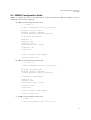
6.9 Provisioning via DRAGON Command Line Interface (CLI)
The following example shows the use of the DRAGON Command Line Interface (CLI) to configure and test if
everything worked right. This example sets up LSPs between sender and receiver host machines,
1.
2.
3.
4.
5.
$ telnet 129.74.43.90 2611
Show the modules and configure them one by one
a. show module
{show what modules we have}
b. configure [MODULE_NAME]
{configure the module}
Create an LSP from the sending side DRAGON CLI
a. edit lsp [LSP_NAME]
{give a name to lsp}
b. set ip_src A.B.C.D port X lsp-id XX ip_dest A.B.C.D port Y tunnel-id YY
{set ip address and
port number for both source and destination}//They must be exactly the same as the receiver side
c. set bandwidth gige swap lsc encoding Ethernet gpid Ethernet
{set
the
switching
capability to be lsc (label switch capability)}
d. exit
Initiate the path from the sender
a. commit lsp [LSP_NAME] {commit to be lsp sender and set up lsp}
Check the LSP status
a. show lsp [LSP_NAME] {show the status of the lsp}
The LSP status is as follows:
Lsp status = In service: the path has been established
= Commit: waiting for responses from the narb
= Edit: has not been committed yet
= Listening: listening for coming path requests
= Delete: waiting for deleting confirmation from the narb
Note: If there is no NARB, the commit command may go to local OSPF daemon to obtain an ERO. DRAGON
daemon behaves differently with NARB configured or under the DRAGON UNI mode. The related commands will
be discussed in following sections.
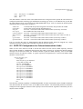
7
Advanced Features
In this section, we present description of three advanced VLSR features that accommodate more sophisticated
networking scenarios. These features are:
•
•
•
VLAN Based Ethernet Circuits
VLSR-to-VLSR (Local-ID) Based Provisioning
DRAGON UNI Provisioning (CSA-to-CSA mode)
19
VLSR Implementation Guide v2.1b
April 2008
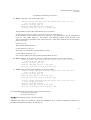
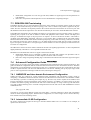
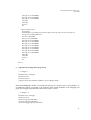
Figure 4 depicts a reference network for illustration of some related network scenarios. We will provide the
configuration details via a combined example in the next section.
Figure 4: Illustration of advanced networking scenarios.
7.1 VLAN Based Ethernet Circuits
The previous sections have described how to configure a VLSR network and provision an LSP crossing a VLSR.
The assumption was that no port is shared by two LSPs. Therefore an intermediate VLSR could simply pick an
empty VLAN and move the inbound and outbound ports into the VLAN in an untagged fashion. The Continuous
End-to-End VLAN feature extends this scenario by creating a VLAN circuit (LSP) with tagged ports all the way
along the path and using a continuous VLAN tag. In so doing, a number of tagged VLANs can share common
switch ports, resulting in a true traffic-grooming-capable Ethernet infrastructure with higher efficiency and
flexibility. As illustrated in Figure 3, the LSP using VLAN 100 can share the data link VLSR1.3ÅÆVLSR2.1 with
another LSP using VLAN 200 without getting their traffic messed with each other.
Continuous end-to-end tagged VLANs can be created in both intra-domain and inter-domain scopes. In both case,
NARB/RCE is required to support the new VLAN constraint in path computation.
Modifications to the DRAGON software in support of this feature include:
• OSPF-TE: configuration and advertisement of available VLAN tags on ports/interfaces
• RSVP-TE: update of VLAN tags during signaling process
• DRAGONd: addition of the set vtag NUM command in LSP definition.
7.2 VLSR-to-VLSR (Local ID) Based Provisioning
Local ID is a feature that enables users to provision LSPs between two edge VLSRs instead of between two end
systems (hosts). In many situations, we do not want or need the end systems to participate in the control process.
All we care about is to provision from one switch port (or group of switch ports) on the ingress VLSR to another
switch port (or group of switch ports) on the egress VLSR.
This feature allows a user to specify the type and number of egress ports which are mapped to the ends of a LSP.
There are four types of Local IDs defined which allow a LSP to be terminated in user defined and flexible
combinations of one port, multiple ports, tagged ports, or untagged ports. The Local ID configurations can be
different at either end of the LSP. In this manner an end to end LSP can be used in multiple application specific
configurations such as connecting a single host on one side of the LSP to a cluster of computers on the opposite LSP
end.
The Local ID feature also requires NARB/RCE since it always works with the Continuous End-to-End VLAN
feature by attaching the ingress/egress ports to a tagged VLAN circuit. Modifications to the DRAGON software in
support of this feature include:
20
VLSR Implementation Guide v2.1b
April 2008
•
•
DRAGONd: configuration of Local ID type and value; addition of ingress/egress Local ID parameters in
LSP definition
RSVP-TE: incorporation and interpretation of Local ID definitions in signaling messages
7.3 DRAGON UNI Provisioning
In GMPLS networks, the User Network Interface allows the clients outside of a network cloud to signal up a tunnel
across this cloud without knowing its interior topology. This is the so called overlay model as against to the peer
model. We have found the UNI especially useful in the scenarios that network customers do not want to peer with
the DRAGON network and expose their own networks and that they do not want to install the DRAGON software.
In the DRAGON architecture, the UNI feature also allows us to support the Proxy Provisioning scenario, in which a
signaling proxy requests for an LSP on behalf of a dumb end equipment such as HDTV camera and display and
telescope. As illustrated in Figure 4, the proxy boxes can request a VLAN circuit between VLSR1.1 and VLSR 2.3
on behalf of the dumb HDTV equipment. The proxy is a low-end PC that is configured as the UNI client running
DRAGON RSVP-TE and DRAGON daemon without participating in the OSPF-TE routing. Under the UNI mode,
the client-side specifies the control channels (e.g., the GRE tunnel between VLSR and end system) on both the
ingress and egress UNI interfaces. The ingress/egress control channels can also be implicitly associated with some
Local IDs via configuration.
The DRAGON UNI uses the same model as defined in the OIF UNI Signaling Specification 1.0 but is implemented
slightly differently. Therefore it is not compatible with the OIF UNI.
Modifications to the DRAGON software in support of this feature include:
• DRAGONd: addition of CLI commands to enable the UNI mode and configure UNI parameters such as
ingress/egress control channels (or define implicit association with a Local ID)
• RSVP-TE: change of signaling handling logic on both the client and network sides of the ingress and egress
UNI
7.4
Advanced Configuration Guide
In this section, we provide a step by step guide to configuration of the example network as depicted in Figure 4. This
guide will illustrate configuration and use of the three advanced features we have described in Section 7. With this
configuration, we will demonstrate provisioning an LSP over a continuous tagged VLAN circuit between two edge
VLSRs in separate domains. The Local ID and DRAGON UNI features will help pick up the proper edge switch
ports as well as signal between the edge VLSR and CSA (at both ingress and egress).
7.4.1 NARB/RCE and Inter-domain Environment Configuration
NARB and RCE are required for VLAN-constrained path computation and inter-domain routing. Guide to
configuring a NARB/RCE based inter-domain network environment has been described in the DRAGON NARB
User Manual [11] Section 4. Following the example in [11], the users only need to replace the IP addresses and
topology information in narb.conf with those of the network in Figure 4. In addition, we need to assign VLAN tags
to links in the abstract topology described in the narb.conf. In this example, we assign VLAN tags 100 and 200 to
every link. Add the following line to each link configuration block in the narb.conf on both NARB/RCE1.100 and
NARB/RCE2.100.
…
vlan_tags(100, 200)
…
Note that we can also assign different VLAN tags among links, a common technique to dictate path computation
results for traffic engineering purpose. With the above configuration, we will no longer need to concern about any
inter-domain issues in the remaining section.
7.4.2 Intermediate VLSR Configuration
We need to advertise the assigned VLAN tags in the intra-domain OSPF areas. Use VLSR1.3 as an example, its
ospfd.conf is shown below.
21
VLSR Implementation Guide v2.1b
April 2008
! -*- ospf -*!
hostname vlsr1-3-ospf
password xxxxxx
!
interface gre1
description GRE tunnel (10.100.1.16/30) between VLSR1.1 and VLSR1.3
ip ospf network point-to-point
!
interface gre3
description GRE tunnel (10.100.1.32/30) between VLSR1.2 and VLSR1.3
ip ospf network point-to-point
!
interface gre4
description GRE tunnel (10.100.1.40/30) between VLSR1.3 and VLSR2.1
ip ospf network point-to-point
!
router ospf
ospf router-id 10.0.1.3
network 10.100.1.16/30 area 0.0.0.0
network 10.100.1.32/30 area 0.0.0.0
passive-interface gre4
!
ospf-te router-address 10.0.1.3
!
ospf-te interface gre1
level gmpls
data-interface ip 10.100.1.21 protocol snmp switch-ip 140.173.4.10 switch-port 1
swcap l2sc encoding Ethernet
max-bw 156250000
max-rsv-bw 156250000
max-lsp-bw 0 156250000
max-lsp-bw 1 156250000
max-lsp-bw 2 156250000
max-lsp-bw 3 156250000
max-lsp-bw 4 156250000
max-lsp-bw 5 156250000
max-lsp-bw 6 156250000
max-lsp-bw 7 156250000
vlan 100
vlan 200
metric 5
exit
!
ospf-te interface gre3
level gmpls
data-interface ip 10.100.1.36 protocol snmp switch-ip 140.173.4.10 switch-port 13
swcap l2sc encoding Ethernet
max-bw 156250000
max-rsv-bw 156250000
22
VLSR Implementation Guide v2.1b
April 2008
max-lsp-bw 0 156250000
max-lsp-bw 1 156250000
max-lsp-bw 2 156250000
max-lsp-bw 3 156250000
max-lsp-bw 4 156250000
max-lsp-bw 5 156250000
max-lsp-bw 6 156250000
max-lsp-bw 7 156250000
vlan 100
vlan 200
metric 5
exit
!
ospf-te interface gre4
level gmpls
data-interface ip 10.100.1.45 protocol snmp switch-ip 140.173.4.10 switch-port 8
swcap l2sc encoding Ethernet
max-bw 1250000000
max-rsv-bw 1250000000
max-lsp-bw 0 1250000000
max-lsp-bw 1 1250000000
max-lsp-bw 2 1250000000
max-lsp-bw 3 1250000000
max-lsp-bw 4 1250000000
max-lsp-bw 5 1250000000
max-lsp-bw 6 1250000000
max-lsp-bw 7 1250000000
vlan 100
vlan 200
metric 10
exit
!
line vty
!
Use similar configuration for the OSPF daemon on other intermediate VLSR nodes. Configurations for all other
components are no different than that described in Section 7. If an intermediate VLSR is also used as an edge node,
refer to the Ingress/Egress VLSR Configuration in the next subsection.
7.4.3 Ingress/Egress VLSR Configuration
On edge VLSR, we need to do the following configurations. Note that both ingress and egress VLSRs are on the
UNI network side and configured the same way. We use the configuration on VLSR1.1 as an example.
a) RSVP-TE configuration (RSVPD.conf)
#
#
RSVPD.conf on VLSR1.1 #
#
# GRE tunnel VLSR1.1-VLSR1.3
interface gre1 tc none mpls
#
23
VLSR Implementation Guide v2.1b
April 2008
# GRE tunnel VLSR1.1-VLSR1.2
interface gre2 tc none mpls
#
# GRE tunnel VLSR1.1-Proxy1.9(ES)
interface gre4 tc none mpls p/1
#
# RSVP API interface
api 4000
#
# definition of NARB API server (host, port)
narb 10.0.1.100 2609
In the interface gre4 line, p/1 is to implicitly associate this control channel (gre2) with the Local ID that
represents the untagged port 1. Here a Local ID is defined in the type/value format. The types include
untagged port (p or P), untagged port group (g or G) and tagged port group (t or T). The value is the port or
group number.
b) OSPF-TE configuration (ospfd.conf)
! -*- ospf -*!
hostname vlsr1-1-ospf
password xxxxxx
!
interface gre1
description GRE tunnel (10.100.1.16/30) between VLSR1.1 and VLSR1.3
ip ospf network point-to-point
!
interface gre2
description GRE tunnel (10.100.1.24/30) between VLSR1.1 and VLSR1.2
ip ospf network point-to-point
!
router ospf
ospf router-id 10.0.1.3
network 10.100.1.16/30 area 0.0.0.0
network 10.100.1.32/30 area 0.0.0.0
passive-interface gre4
!
ospf-te router-address 10.0.1.3
!
ospf-te interface gre1
level gmpls
data-interface ip 10.100.1.22 protocol snmp switch-ip 140.173.2.8 switch-port 8
swcap l2sc encoding Ethernet
max-bw 156250000
max-rsv-bw 156250000
max-lsp-bw 0 156250000
max-lsp-bw 1 156250000
max-lsp-bw 2 156250000
max-lsp-bw 3 156250000
max-lsp-bw 4 156250000
24
VLSR Implementation Guide v2.1b
April 2008
max-lsp-bw 5 156250000
max-lsp-bw 6 156250000
max-lsp-bw 7 156250000
vlan 100
vlan 200
metric 5
exit
!
ospf-te interface gre2
level gmpls
data-interface ip 10.100.1.29 protocol snmp switch-ip 140.173.2.8 switch-port 14
swcap l2sc encoding Ethernet
max-bw 156250000
max-rsv-bw 156250000
max-lsp-bw 0 156250000
max-lsp-bw 1 156250000
max-lsp-bw 2 156250000
max-lsp-bw 3 156250000
max-lsp-bw 4 156250000
max-lsp-bw 5 156250000
max-lsp-bw 6 156250000
max-lsp-bw 7 156250000
vlan 100
vlan 200
metric 5
exit
!
line vty
!
c)
dragon daemon configuration (dragon.conf)
! -*- dragon -*!
hostname vlsr1-1-dragon
password xxxxxx
set local-id port 1
configure narb intra-domain ip-address 10.0.1.100 port 2609
!
Here set local-id port 1 defines a Local ID with the type port and the value 1 (port number). As
an additional example on VLSR1.2, the following lines include definition of an untagged port
group and a tagged group that both contain the two ports 1 and 9.
! -*- dragon) -*!
hostname vlsr1-2-dragon
password xxxxxx
set local-id group 1000 add 1
set local-id group 1000 add 9
set local-id tagged-group 1001 add 1
25
VLSR Implementation Guide v2.1b
April 2008
set local-id tagged-group 1001 add 9
configure narb intra-domain ip-address 10.0.1.100 port 2609
!
7.4.4 Ingress/Egress End System Configuration
No OSPF-TE is available on the end system which is configured as the UNI client. We only need to configure
RSVP-TE and DRAOGN daemon. In this example the two end systems (or UNI clients) are Proxy1.9 and Proxy2.9.
The example configurations on Proxy1.9 are as follows.
a) RSVP-TE configuration (RSVPD.conf)
#
#
RSVPD.conf on Proxy1.9 #
#
# GRE tunnel VLSR1.1—Proxy1.9(ES)
interface gre4 tc none mpls p/1
#
# RSVP API interface
api 4000
#
b) DRAGON daemon configuration (dragon.conf)
! -*- dragon -*!
hostname proxy1-9
password xxxxxx
set local-id port 1
!
Deferent than the configurations on the edge VLSR (the UNI network side), there is no NARB API information
defined for both RSVPD.conf and dragon.conf.
7.4.5 Provisioning via DRAGON UNI
To provision an LSP between the two UNI clients Proxy1.9 and Proxy2.9 (on behalf of the HDTV camera and
display respectively), issue the following commands via the DRAGON daemon CLI on Proxy1.9.
$ telnet 10.0.1.9 2611
proxy1-9> edit lsp test1
proxy1-9(edit-lsp-test1)# set uni client ingress implicit egress implicit
proxy1-9(edit-lsp-test1)# set source ip 10.0.1.1 port 1 destination ip-address 10.0.2.3 port 9
proxy1-9(edit-lsp-test1)# set bandwidth gige swcap l2sc encoding Ethernet gpid Ethernet
proxy1-9(edit-lsp-test1)# set vtag 100
proxy1-9(edit-lsp-test1)# exit
proxy1-9> commit lsp test1
Line 3 is to set the LSP to UNI mode and tell the DRAGON RSVP-TE to use the ingress and egress
control channels that are implied by the associated Local ID definitions. An alternate definition in this
case could be
26
VLSR Implementation Guide v2.1b
April 2008
# set uni client ingress gre4 egress gre9
where gre4 and gre9 are explicitly specified as the ingress and egress GRE tunnels on the UNI
interfaces of both ends respectively.
Line 4 replaces the lsp-id and tunnel-id (see Section 9) with the Local ID definitions, which will be
interpreted by the DRAGON RSVP-TE as signaling operations to attach switch port 1 on VLSR1.1 and
switch port 8 on VLSR2.3 to the two ends of the LSP. This LSP (VLAN circuit) will use a continuous tag
100 as specified by the Line 6.
7.4.6
VLSR-to-VLSR (Local-ID) Based Provisioning
An LSP can also be provisioned directly between two edge VLSRs without initiation from an end system or UNI
client. For example, we can provision an LSP from the untagged port group 1000 (containing untagged ports 1 and
9) on VLSR1.2 to the untagged port 8 on VLSR2.2 over the tagged VLAN 200 just by using the following
commands via the DRAGON CLI on VLSR1.2.
$telnet 10.0.1.2 2611
vlsr1-2-dragon> edit lsp test2
vlsr1-2-dragon(edit-lsp-test2)# set source ip 10.0.1.2 group 1000 destination ip-address 10.0.2.2
port 8
vlsr1-2-dragon(edit-lsp-test2)# set bandwidth gige swcap l2sc encoding Ethernet gpid Ethernet
vlsr1-2-dragon(edit-lsp-test2)# set vtag 200
vlsr1-2-dragon(edit-lsp-test2)# exit
vlsr1-2-dragon> commit lsp test2
By replacing Line 3 with the following command we will attach the ports 1 and 9 on VLSR1.2 to the
VLAN circuit in a tagged fashion. The tag on the ports must match the tag of the VLAN circuit, i.e., 200.
On the egress end, port 8 can remain untagged.
# set source ip 10.0.1.2 group 1001 destination ip-address 10.0.2.2 port 8
One can verify whether the data path is set up as follows.
1. The LSP status becomes in-service in DRAGON CLI
# show lsp test2 (see Section 9)
2. If the two client systems are PC hosts, configure the IP addresses of Ethernet interfaces at both
ends in the same network segment. Use ping (or jumbo ping if applicable). Otherwise, if the client
systems are dumb equipment, try the actual data transfer to check the data-plane connectivity.
8
Linux Software Switch Configuration
Linux software switch is a VLSR emulated Ethernet switch that uses the Linux network interface and
bridge configuration commands, such as ifocnfig, vconfig and brctl, to create VLANs via the operating
system. To configure and compile the VLSR code in the Linux software switch mode, run the build scrip
as ‘root.’
# ./do_build.sh vlsr-linux
Input ‘shell’ as the ‘CLI Session Type’ for switch operation and enter on the prompts for user name and
password.
The data-plane ports of the Linux switch are the Ethernet interfaces of the OS, e.g., eth1, eth2 etc. A GRE
control channel should be created for each data interface. The data-interface IP can be the same as the
27
VLSR Implementation Guide v2.1b
April 2008
GRE interface. The following command in the DRAGON VLSR distribution can be used to determine the
switch-port number for each Ethernet data interface.
# ./utils/show-linux-switch-ports.pl
The output will look like the following.
interface lo --> port #1 (0/0/1)
interface eth0 --> port #2 (0/0/2)
interface eth1 --> port #3 (0/0/3)
interface eth2 --> port #4 (0/0/4)
All related configuration in ospfd.conf is the same as for the VLSR of a regular Ethernet switch. The
dragon CLI commands for LSP provisioning will also be the same as for the VLSR of a regular Ethernet
switch.
9
Ethernet-over-SONET Subnet Configuration
Ethernet-over-SONET (EoS) Subnet VLSR is special that it controls a group of networked switches
instead of single ones. In the current implementation, we point to a subnet with Ciena CoreDirector
SONET switches that support Ethernet at edge ports. Each VLSR controls one, more or all the
CoreDirector switches in the subnet. In particular, a subnet VLSR operates on a select set of Ethernet
termination ports (ETTP) that could belong to one of more switches.
Firstly, we need to build the DRAON VLSR software in the subnet mode.
./do_build.sh vlsr-subnet
Input ‘TL1’ as the ‘CLI Session Type’ for switch operation and the user name and password for the TL1
management account.
9.1 OSPF-TE Configuration for Subnet ETTP Interfaces
We need to add each ETTP into GMPLS OSPF-TE. We firstly create a GRE tunnel as the control
interface for that ETTP. The GRE tunnel can be either connecting to real peer as in an interdomain TE
link, or simply pointing to nowhere. An example ospfd.conf configuration for the GRE control interface is
shown below.
(1) ospf-te interface gre4
(2)
level gmpls
(3)
data-interface ip 10.100.80.133
(4)
swcap l2sc encoding ethernet
(5)
subnet-uni 101 node-name WASH tna-ipv4 10.100.10.233 uni-n-ipv4 64.57.24.64 controlchannel implicit data-interface 10.100.80.133 port 1-A-5-1-3 egress-label 1000 upstream-label 2000
(6)
subnet-uni swcap-ext tdm encoding-ext sdh
(7)
timeslot 1 to 21
(9)
max-bw 125000000
(10)
max-rsv-bw 125000000
(11)
max-lsp-bw 0 125000000
(12)
max-lsp-bw 1 125000000
(13)
max-lsp-bw 2 125000000
(14)
max-lsp-bw 3 125000000
(15)
max-lsp-bw 4 125000000
(16)
max-lsp-bw 5 125000000
(17)
max-lsp-bw 6 125000000
28
VLSR Implementation Guide v2.1b
April 2008
(18)
(19)
(20)
max-lsp-bw 7 125000000
metric 100
exit
The data-interface can be the same as the GRE interface IP or assigned with a separate IP. The interface is
configured with L2SC switching type and Ethernet encoding type in line (4). In addition line (6) tells that
the L2SC Ethernet layer can be mapped to TDM SDH/SONET layer. Line (5) contains the ETTP specific
information that is broken down as follows.
subnet-uni:
node-name:
tna-ipv4:
uni-n-ipv4:
control-channel:
data-interface:
port:
egress-label:
upstream-label:
a interface ID the operator assigned to the ETTP, unique under the VLSR
name of the switch node the ETTP belongs to
not used – reserved for OIF UNI2.0 based control (can be any A.B.C.D)
the routable IP of the switch node
not used – reserved for OIF UNI2.0 based control (set to ‘implicit’)
not used – reserved for OIF UNI2.0 based control (set to the same as in line 3)
the ETTP port name
not used – reserved for OIF UNI2.0 based control (can be any number)
not used – reserved for OIF UNI2.0 based control (can be any number)
Line (7) specifies the range of TDM timeslots that the Ethernet traffic should be mapped into, which
should be consistent with the link bandwidth specified by the lines below it.
9.2 OSPF-TE Configuration for Subnet Intermediate Links
When we have more than one VLSR to divide and control the same subnet, OSPF adjacency between
these VLSRs should be established following the data plane connectivity such that the RSVP signaling
messages can be delivered from one VLSR to another. Again the OSPF adjacency relies on the GRE
tunnels between the adjacent VLSRs. A typical ospfd.conf configuration for such an intermediate GRE
interface is shown below.
ospf-te interface gre5
level gmpls
data-interface ip 10.100.80.45
swcap tdm encoding sdh
max-bw 1250000000
max-rsv-bw 1250000000
max-lsp-bw 0 1250000000
max-lsp-bw 1 1250000000
max-lsp-bw 2 1250000000
max-lsp-bw 3 1250000000
max-lsp-bw 4 1250000000
max-lsp-bw 5 1250000000
max-lsp-bw 6 1250000000
max-lsp-bw 7 1250000000
metric 100
exit
Note that the switching capability is TDM SDH/SONET for these intermediate subnet VLSR-VLSR links.
The data-interface IP can be the same as the GRE control interface. The bandwidth parameters should be
configured as the aggregate amount of link capacity between the network segments controlled by the two
adjacent subnet VLSRs.
29
VLSR Implementation Guide v2.1b
April 2008
9.3 DRAGON CLI Based Provisioning
In addition to the above edge and intermediate subnet VLSR interface configuration, we also need to
configure subnet local ID in dragon.conf such that RSVP signaling can determine the proper source and
destination ETTP interfaces from the DRAGON CLI LSP provisioning commands.
The following commands will set up the subnet-interface type of local ID.
(1) set local-id subnet-interface 101/1
(2) set local-id subnet-interface 101/255
(3) set local-id subnet-interface 101
In command (1), the first number 101 is the unique subnet interface ID of the ETTP. The second number
1 represents the starting of a timeslot range that Ethernet traffic is mapped into. The actually number of
timeslots in the range will depend on the LSP bandwidth value. If the starting timeslot number is 255 as
shown in command (2), the system will pick ‘any’ timeslot based on NARB path computation results.
Command (3) is equivalent to (2).
By default, every 50 Mbps of Ethernet bandwidth is mapped into one TDM timeslot (STS-1). DRAGON
provides an option in RSVPD.conf to fine tune the mapping. For example, to map 1000 Mbps (1 GigE)
into 21 timeslots, either of the following two commands should be added to the RSVPD.conf on all
subnet VLSRs.
eos_map 1000 sts-1 21
eos_map 1000 sts-3c 7
The following DRAGON CLI commands provodes an example for VLSR-VLSR LSP provisioning
between two ETTPs in a subnet.
edit lsp test004
set source ip-address 10.100.80.206 subnet-interface 26111 destination ip-address 10.100.80.222
subnet-interface 26623
set bandwidth eth300M swcap l2sc encoding ethernet gpid ethernet
set vtag 3000
exit
commit lsp test004
Compared to previous provisioning commands, the only difference is the use of subnet-interface type of
local IDs. In this example, 26111 is subnet-interafce local-id 101/255 and 26623 is 103/255, which can be
seen by the show local-id command. Note that when both the source and destination ETTPs (local IDs)
are controlled by the same VLSR, the source and destination ip-address will be the same.
10 Conclusion
The DRAGON VLSR implementation guide as described in this document is intended to provide the
necessary information for users and developers to successfully install the VLSR software and implement
a VLSR-based network. The basic installation and configuration guide is provided for beginning users to
implement a minimum VLSR network that can provision VLAN connections between end hosts attached
to a single (or a few) VLSR switch. Additional configuration guide is provided for advanced users to
implement more sophisticated networking environments with the support of several advanced VLSR
features.
The latest version of this document can be downloaded from http://dragon.east.isi.edu.
30
VLSR Implementation Guide v2.1b
April 2008
11 DRAGON Project
This document was generated by the University of Southern California (USC) Information Sciences Institute (ISI),
University of Maryland (UMD) Mid-Atlantic Crossroads (MAX), and George Mason University (GMU) as part of
the National Science Foundation funded Dynamic Resource Allocation via GMPLS Optical Networks (DRAGON)
project. Additional details regarding this project are available at http://dragon.east.isi.edu.
31
VLSR Implementation Guide v2.1b
April 2008
Appendix A: Acronyms and Abbreviations
¾
¾
¾
¾
¾
¾
¾
¾
¾
¾
¾
¾
¾
¾
¾
¾
¾
¾
¾
¾
¾
¾
¾
¾
¾
¾
¾
¾
¾
¾
¾
¾
API: Application Programming Interface
BGP Border Gateway Protocol
CLI: Command Line Interface
CSA: Client System Agent
CSPF: Constrained Shortest Path First
CVS: Concurrent Version Systems
DRAGON: Dynamic Resource Allocation in GMPLS Optical Networks
EoS: Ethernet-over-SONET
ESA: End System Agent
GCC: GNU Compiler Collection
GNU: GNU's Not Unix
GMPLS: Generalized Multi-Protocol Label Switching
GRE: Generic Routing Encapsulation
IP: Internet Protocol
LSDB: Link State DataBase
LSR: Label Switch Router
LSP: Label Switched Paths
NARB: Network Aware Resource Broker
OSPF: Open Shortest Path First
OSPF-TE: Open Shortest Path First-Traffic Engineering
RAM: Random Access Memory
RCE: Resource Computation Element
RFC: Request for Comments
RIP: Routing Information Protocol
RSVP : Resource Reservation Protocol
RSVP-TE: Resource Reservation Protocol-Traffic Engineering
SNMP: Simple Network Management Protocol
SSH: Secure SHell
SVN: SubVersioN
UNI: User Network Interface
VLSR: Virtual Label Switching Router
XML: Extensible Markup Language
32
VLSR Implementation Guide v2.1b
April 2008
Appendix B: Optional DRAGON CLI Commands
This appendix presents some optional DRAGON CLI commands that are useful but not be able to place in any
previous sections.
B.1. Setting NARB Path Computation Options
There is a set of optional commands that indicate special path computation options when querying a path from
NARB.
set narb-extra-options query-with-confirmation
set narb-extra-options query-with-holding
set narb-extra-options query-subnet-ero
set narb-extra-options query-subnet-dtl
set narb-extra-options none
The first four commands turn on the NARB options for Q-Conf, Q-Hold, Subnet-ERO and Subnet-DTL.
Explanations of these options can be found in [10] and [11]. When the Q-Conf option is turned on, ‘show lsp
NAME’ will display the Global Resource ID (GRI) that served as the confirmation ID associated with the LSP. The
last command ‘set narb-extra-options none’ clears all the above options.
B.2. User Supplied ERO
A user can supply an ERO to DRAGON signaling via CLI under the ‘edit lsp lsp-name’ statement.
edit lsp test1
set source ip-address 10.100.80.222 subnet-interface 26623 destination ip-address 10.100.80.203 subnet-interface 26367
set bandwidth eth300M swcap l2sc encoding ethernet gpid ethernet
set ero-hop-ipv4 strict ip-address 10.100.80.33
set ero-hop-ipv4 strict ip-address 10.100.80.34
set ero-hop-ipv4 strict ip-address 10.100.80.53
set ero-hop-ipv4 strict ip-address 10.100.80.54
set vtag 3001
exit
commit lsp test1
In this example, a sequence of ERO IPv4 subobjects is supplied to compose an ERO. When the LSP is committed, a
path request will still be sent to NARB and a path reply with NARB-computed ERO will be sent back upon
successful path computation. In this case, the NARB-computed ERO will contain two subobjects that indicate
reserved edge timeslots based on the subnet-interface Local IDs, which will be kept. The intermediate hops will be
overridden by the user-supplied ERO. In other cases, user may supply ERO subobjects for intermediate VLAN
tagged hops and Ethernet Local IDs, using the following command:
set ero-hop (strict|loose) ip-address A.B.C.D interface-id ID
An ERO is formed when user exits the ‘edit lsp lsp-name’ statement. When user reedits the same LSP, the ERO hop
list will be cleared.
B.3. User Supplied Subnet DTL
When the current domain contains a subnet and supports the subnet control model [10], a user can also supply a
subnet Designated Transit List (DTL) to DRAGON signaling via CLI under the ‘edit lsp lsp-name’ statement.
edit lsp test2
set source ip-address 10.100.80.222 subnet-interface 26623 destination ip-address 10.100.80.203 subnet-interface 26367
set bandwidth eth300M swcap l2sc encoding ethernet gpid ethernet
set dtl-hop node SUNN link 1
set dtl-hop node SALT link 1
set dtl-hop node DENV link 1
set dtl-hop node KANS link 1
33
VLSR Implementation Guide v2.1b
April 2008
set dtl-hop node CHIC link 1
set dtl-hop node CLEV link 2
set dtl-hop node PITT link 1
set vtag 3002
exit
commit lsp test2
Information about use of subnet DTL can be found in [10] and [11].
B.4. Subnet Ingress and Egress VLAN Tags/Modes
In addition to DTL, a circuit crossing an EoS subnet can also be provisioned with specific ingress and/or egress
VLAN tags/modes using the commands ‘set vtag subnet-ingress NAME’ and ‘set vtag subnet-egress NAME,’ where
the NAME field could be a specific VLAN tag in the range <1, 4095> or ‘untagged’ or ‘tunnel-mode’.
The ingress and egress VLAN tags/modes may differ, which enables VLAN tag/mode translations. For example, the
following commands translate an ingress VLAN tag 3100 into an egress VLAN tag 3200 in the EoS subnet.
edit lsp test3
set source ip-address 10.100.80.222 subnet-interface 26623 destination ip-address 10.100.80.203 subnet-interface 26367
set bandwidth eth300M swcap l2sc encoding ethernet gpid Ethernet
set vtag subnet-ingress 3100
set vtag subnet-egress 3200
exit
commit lsp test3
And the following commands translate between tagged and untagged modes.
edit lsp test4
set source ip-address 10.100.80.222 subnet-interface 26623 destination ip-address 10.100.80.203 subnet-interface 26367
set bandwidth eth300M swcap l2sc encoding ethernet gpid Ethernet
set vtag subnet-ingress 3003
set vtag subnet-egress untagged
exit
commit lsp test4
Or between tagged and tunnel modes. (And any other combinations work too.)
edit lsp test5
set source ip-address 10.100.80.222 subnet-interface 26623 destination ip-address 10.100.80.203 subnet-interface 26367
set bandwidth eth300M swcap l2sc encoding ethernet gpid Ethernet
set vtag subnet-ingress 3004
set vtag subnet-egress tunnel-mode
exit
commit lsp test5
Without the ‘set vtag subnet-ingress’ and ‘set vtag subnet-egress’ commands, ‘set vtag TAG’ means tagged mode and
specifies a VLAN tag for both subnet ingress and egress, ‘set vtag any’ means tunnel mode and lack of the ‘set vtag’
command means untagged mode by default. When only one of the ‘set vtag subnet-ingress’ and ‘set vtag subnet-egress’
commands is used, the other edge takes the default value. For example, the following commands are equivalent to
the above ‘edit lsp test4’ commands.
edit lsp test6
set source ip-address 10.100.80.222 subnet-interface 26623 destination ip-address 10.100.80.203 subnet-interface 26367
set bandwidth eth300M swcap l2sc encoding ethernet gpid Ethernet
set vtag subnet-ingress 3003
exit
commit lsp test6
34
VLSR Implementation Guide v2.1b
April 2008
Appendix C: References
1 Thomas Lehman, Jerry Sobieski, Bijan Jabbari, DRAGON: A Framework for Service Provisioning in
Heterogeneous Grid Networks, IEEE Communications Magazine, pp. 84-90, March 2006.
2 Xi Yang, Tom Lehman, Chris Tracy, Jerry Sobieski, Shujia Gong, Payam Torab, Bijan Jabbari, "Policy-Based
Resource Management and Service Provisioning in GMPLS Networks", Adaptive Policy-based Management in
Network Management and Control Workshop at INFOCOMM 2006, Barcelona Spain, April 2006.
3 K. Kompella, Y. Rekhter, OSPF Extensions in Support of Generalized Multi-Protocol Label Switching, RFC
4203, October 2005.
4 L. Berger, Generalized Multi-Protocol Label Switching (GMPLS) Signaling Resource ReserVation ProtocolTraffic Engineering (RSVP-TE) Extensions, RFC 3473, January 2003.
5 Xi Yang, Tom Lehman, Chris Tracy, Jerry Sobieski, GMPLS-Based Dynamic Provisioning and Traffic
Engineering of High-Capacity Ethernet Circuits in Hybrid Optical/Packet Networks, High Speed Networking, The
Terabits Challenge Workshop at INFOCOMM 2006, Barcelona Spain, April 2006.
6 E.Bell, A.Smith, P.Langille, A.Rijhsinghani, K.McLoghrie, "Definitions of Managed Objects for Bridges with
Traffic Classes, Multicast Filtering and Virtual LAN Extensions", RFC 2674, August 1999.
7 GNU Zebra Routing Protocol Suite, http://www.zebra.org
8 M. Karsten, KOM RSVP Engine, http://www.kom.e-technik.tu-darmstadt.de/rsvp/
9 NARB and RCE Architecture, April 2008, http://dragon.east.isi.edu
10 NARB Design and User Manual, April 2008, http://dragon.east.isi.edu
11 RCE Design and User Manual, April 2008, http://dragon.east.isi.edu
35